Download as PDF, PPTX


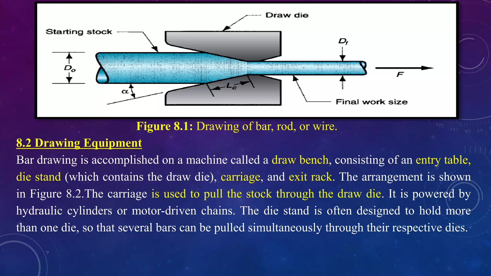
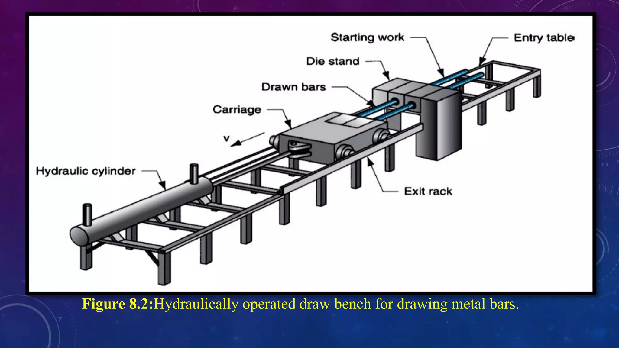
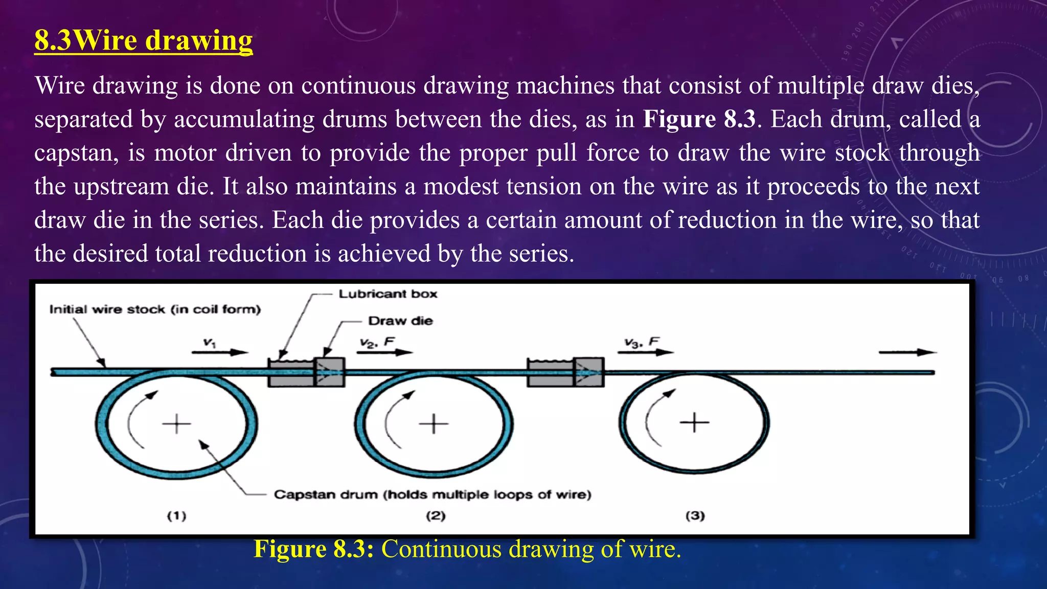

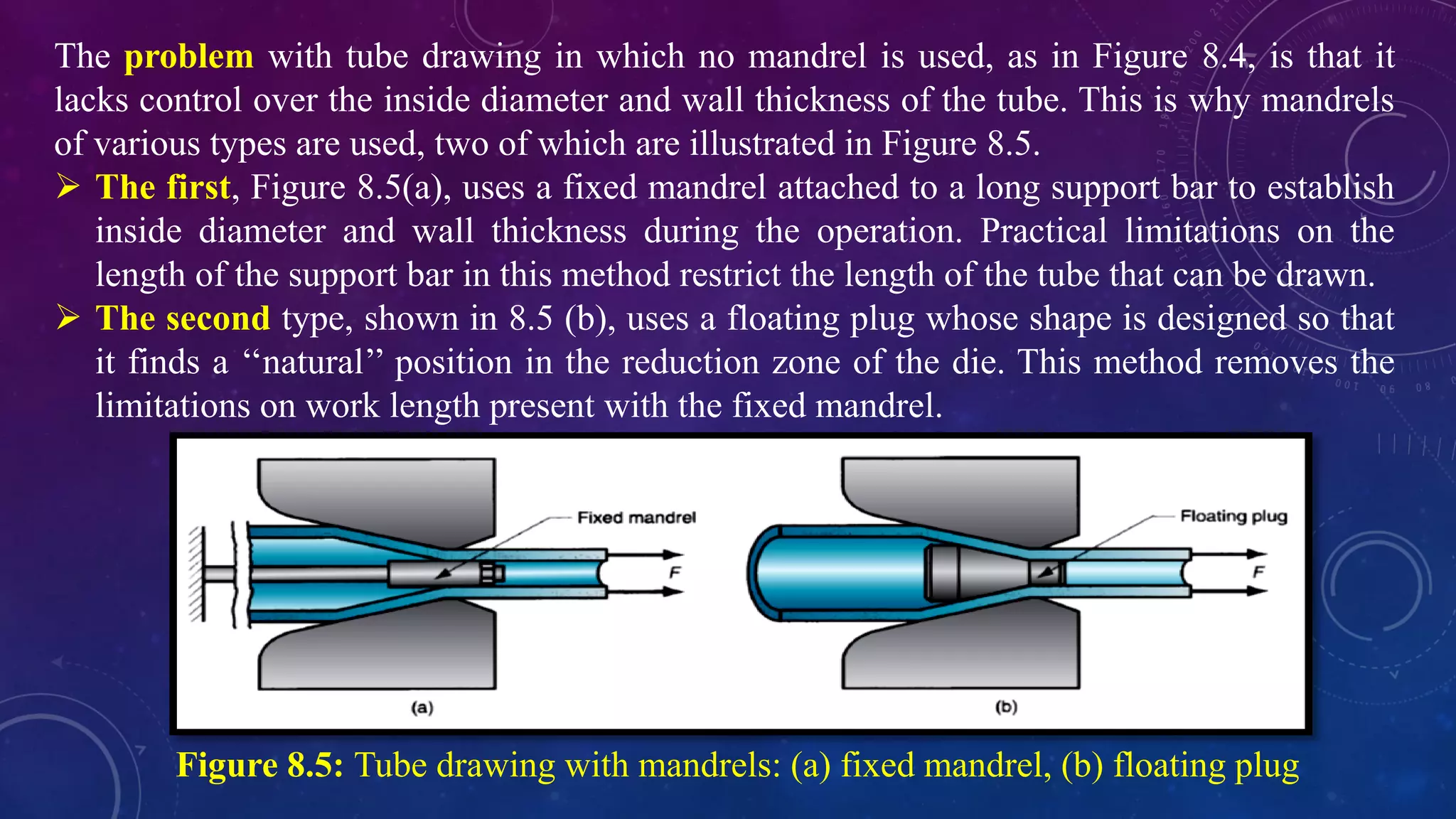
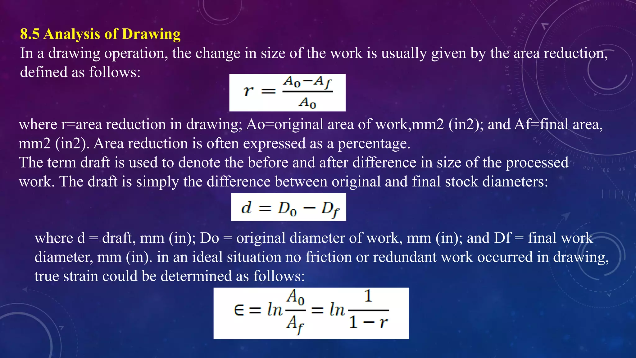


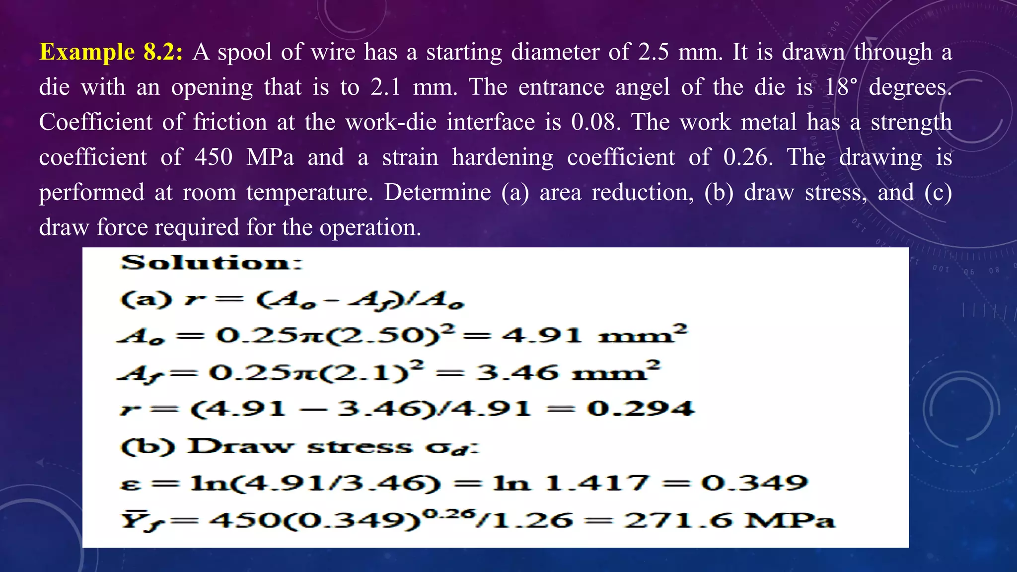


The document discusses wire and bar drawing, a process that reduces the cross-section of metal by pulling it through a die, with key differences from extrusion. It elaborates on equipment used for drawing, highlighting the roles of draw benches and continuous drawing machines, and addresses tube drawing techniques, including the use of mandrels. Additionally, it covers the analysis of drawing operations, including calculations for area reduction, draft, draw stress, and power requirements.