Wissam Geahchan presented an overview of the cable manufacturing process. The presentation covered:
- A brief history of cable development over the past 200+ years.
- Key materials used in cable manufacturing including copper, silver, gold, aluminum and polymer compounds.
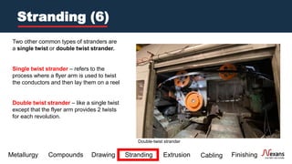
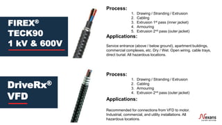
- Main manufacturing processes such as drawing, stranding, extrusion and cabling to transform raw materials into a finished cable product.
- Testing and quality assurance measures to ensure cables meet specifications.
The presentation provided information on the various stages of cable manufacturing from raw materials to finished product.


![[Learn all you can about the
history of the past, for how else
can one even guess what is
going to happen in the future.]
Winston Churchill
A Brief History (1)](https://image.slidesharecdn.com/cablemanufacturing101-230717021148-8ba7f764/85/Cable-Manufacturing-101-pdf-8-320.jpg)