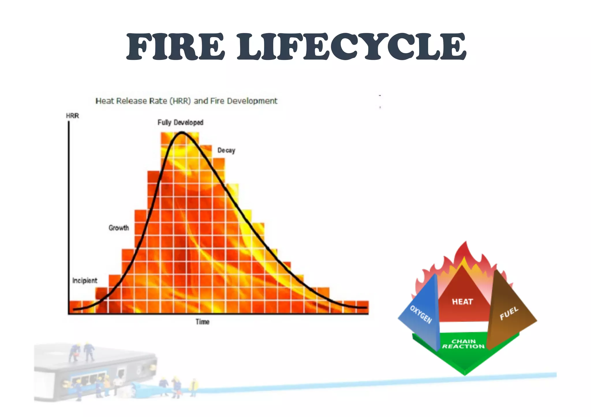
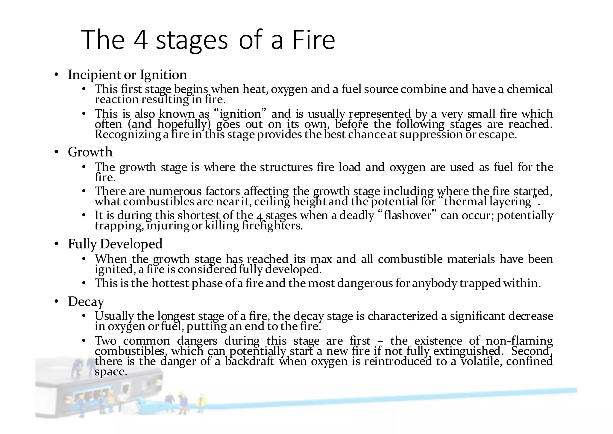
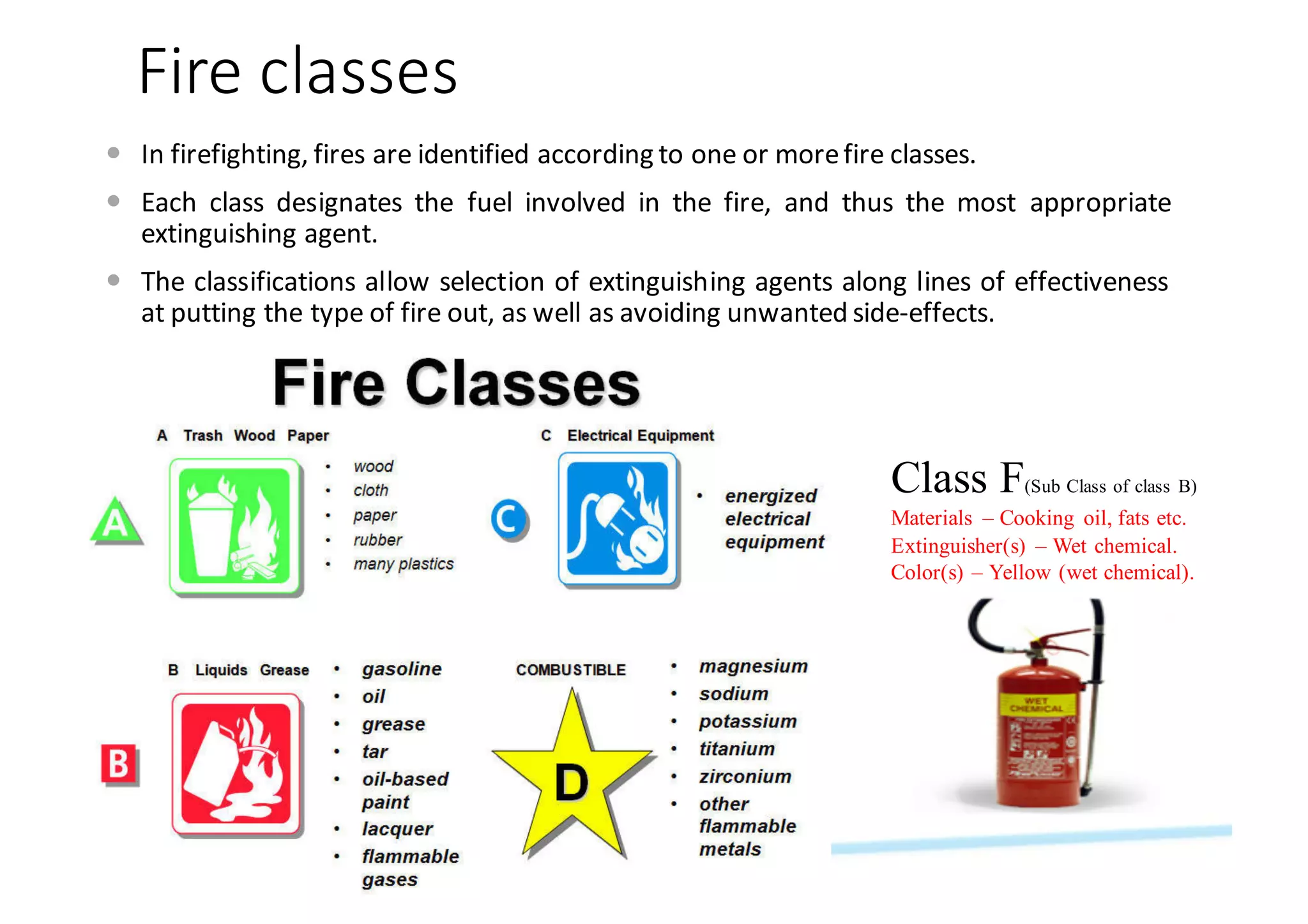
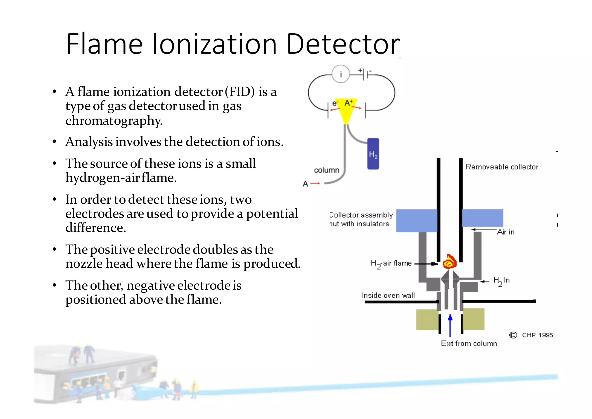
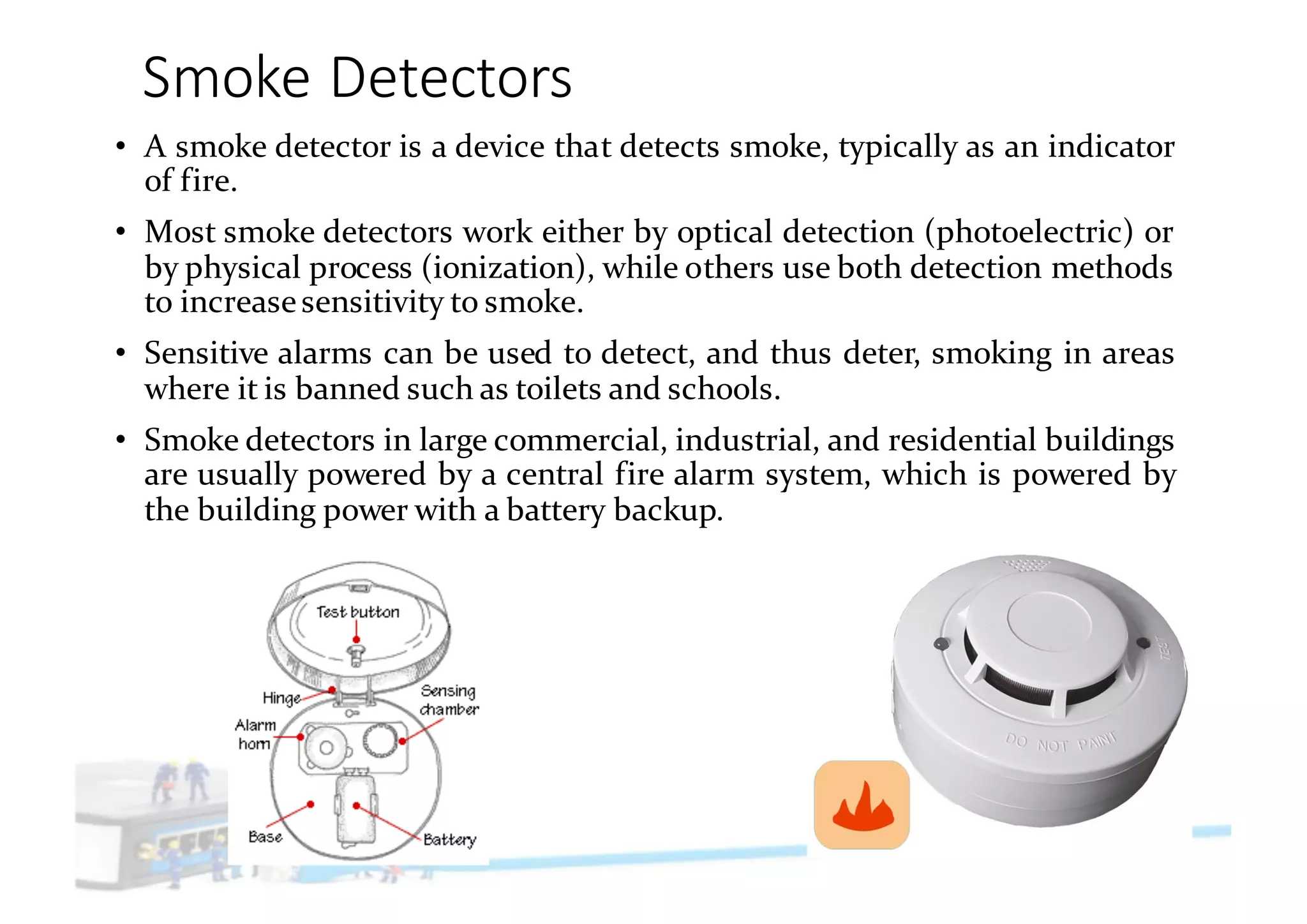
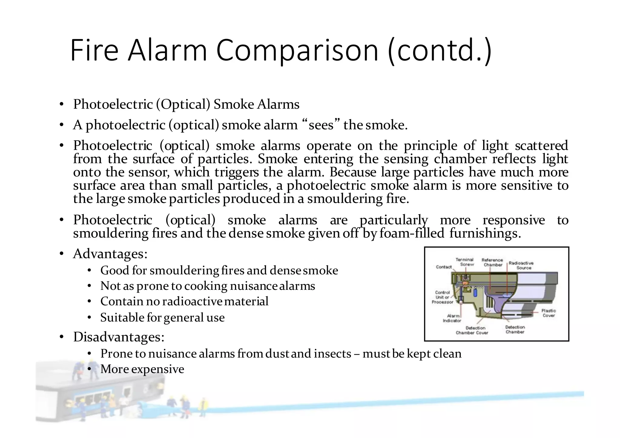
FIRE LIFECYCLE
The	4	stages	of	a	Fire
• Incipient or Ignition
• This first stage begins when heat, oxygen and a fuel source combine and have a chemical
reaction resulting in fire.
• This is also known as ignition and is usually represented by a very small fire which
often (and hopefully) goes out on its own, before the following stages are reached.
Recognizinga fire in this stage provides the best chanceat suppression orescape.
• Growth
• The growth stage is where the structures fire load and oxygen are used as fuel for the
fire.
• There are numerous factors affecting the growth stage including where the fire started,
what combustibles are nearit, ceiling heightand the potential for thermal layering .
• It is during this shortest of the 4 stages when a deadly flashover can occur; potentially
trapping, injuringorkilling firefighters.
• Fully Developed
• When the growth stage has reached its max and all combustible materials have been
ignited, a fire is consideredfully developed.
• This is the hottest phase of a fire and the most dangerous foranybody trappedwithin.
• Decay
• Usually the longest stage of a fire, the decay stage is characterized a significant decrease
in oxygen orfuel, putting an end to the fire.
• Two common dangers during this stage are first – the existence of non-flaming
combustibles, which can potentially start a new fire if not fully extinguished. Second,
there is the danger of a backdraft when oxygen is reintroduced to a volatile, confined
space.
Impacts	of	fire
• impact of large-scale uncontrolled fires,at a global scale:
• they can influencethe chemical compositionof the atmosphere
and the reflectivityof the Earth s surface.
• At the regional and local scale,
• forest fires change biomass stocks,
• reducevisibilityto near zero,
• Impact plant and animal species functioning
• Detrimentally impact the health and livelihoods of the human
population
• Smoke from fires cansignificantlyreducephotosynthetic activity
Fire	classes
— In firefighting, fires are identified according to one or morefire classes.
— Each class designates the fuel involved in the fire, and thus the most appropriate
extinguishing agent.
— The classifications allow selection of extinguishing agents along lines of effectiveness
at putting the type of fire out, as well as avoiding unwanted side-effects.
Class F(Sub Class of class B)
Materials – Cooking oil, fats etc.
Extinguisher(s) – Wet chemical.
Color(s) – Yellow (wet chemical).
Characteristics	of	Fire	classes
• Class A (Ordinary Combustibles)
• This fire is not dangerous, because the fire is contained to the wood alone and is usually isolated from
other flammable materials, for example by bare ground and rocks.
• However, when a class-A fire burns in a less-restricted environment the fire can quickly grow out of
control and become a wildfire.
• This is the case when firefighting and fire control techniques are required.
• Class B (Flammable liquid and gas)
• These fires follow the same basic fire tetrahedron (heat, fuel, oxygen, chemical reaction) as ordinary
combustible fires, except that the fuel in question is a flammable liquid such as gasoline, or gas such as
natural gas.
• A solid stream of water should never be used to extinguish this type because it can cause the fuel to
scatter, spreading the flames.
• The most effective way to extinguish a liquid or gas fueled fire is by dry chemical and Halon
extinguishing agents, although smothering with CO2 or, for liquids, foam is also effective.
• Class C (Electrical)
• This sort of fire may be caused by short-circuiting machinery or overloaded electrical cables.
• These fires can be a severe hazard to firefighters using water or other conductive agents.
• Water, foam, and other conductive agents are not to be used to extinguish this fire type, but CO2 may be
used
• Class D (Metal)
• Water and other common firefighting materials can excite metal fires and make them worse.
• Metal fires be fought with "dry powder" extinguishing agents.
• Dry powder agents work by smothering and heat absorption.
• The most common of these agents are sodium chloride granules and graphite powder.
Flame	Ionization	Detector
• A flame ionization detector(FID) is a
type of gas detectorused in gas
chromatography.
• Analysis involves the detection of ions.
• The source of these ions is a small
hydrogen-airflame.
• In order todetect these ions, two
electrodes are used toprovide a potential
difference.
• The positive electrode doubles as the
nozzle head where the flame is produced.
• The other, negative electrode is
positioned above the flame.
Smoke	Detectors
• A smoke detector is a device that detects smoke, typically as an indicator
of fire.
• Most smoke detectors work either by optical detection (photoelectric) or
by physical process (ionization), while others use both detection methods
to increasesensitivity to smoke.
• Sensitive alarms can be used to detect, and thus deter, smoking in areas
where it is banned such as toilets and schools.
• Smoke detectors in large commercial, industrial, and residential buildings
are usually powered by a central fire alarm system, which is powered by
the building power with a battery backup.
Fire	Alarm	Comparison
• Ionization smoke alarms use a small amount of radioactive material that
ionizes the air between two electrically charged plates, causing a current to
flow between the plates. When smoke enters the chamber, it changes the
flowof current, which is detected and activates the alarm.
• Ionization smoke alarms activate more quickly for fast, flaming fires with
little visiblesmoke.
• Advantages:
• Cheaper than other types of smoke alarms
• Very good with fast flaming fires with little visible smoke
• Suitable forgeneral use
• Less prone to false alarms due todust and steam
• Disadvantages:
• Very susceptible tonuisance alarms due to cooking
• May be slow to respond to slow smouldering fires
• Contain radioactive material
Fire	Alarm	Comparison	(contd.)
• Photoelectric (Optical) Smoke Alarms
• A photoelectric (optical) smoke alarm sees the smoke.
• Photoelectric (optical) smoke alarms operate on the principle of light scattered
from the surface of particles. Smoke entering the sensing chamber reflects light
onto the sensor, which triggers the alarm. Because large particles have much more
surface area than small particles, a photoelectric smoke alarm is more sensitive to
the large smoke particles produced in a smouldering fire.
• Photoelectric (optical) smoke alarms are particularly more responsive to
smouldering fires and the dense smoke given off by foam-filled furnishings.
• Advantages:
• Good for smoulderingfires and densesmoke
• Not as prone to cooking nuisancealarms
• Contain no radioactivematerial
• Suitable forgeneral use
• Disadvantages:
• Prone to nuisance alarms fromdustand insects – mustbe kept clean
• More expensive
Heat	(RoR)	Detectors
• A heat detector is a fire alarm device designed to respond when the convected
thermal energy of a fire increases the temperature of a heat sensitive element.
• The thermal mass and conductivity of the element regulate the rate flow of heat
into the element.
• All heat detectors have this thermal lag. Heat detectors have two main
classifications of operation, "rate-of-rise" and "fixed temperature.
• Rate-of-Rise (ROR) heat detectors operate on a rapid rise in element temperature
of 120° to 150°F (67° to 83°C) increase per minute, irrespective of the starting
temperature.
• This type of heat detector can operate at a lower temperature fire condition than
would be possible if the threshold were fixed.
• It has two heat-sensitive thermocouples/ thermistor. One thermocouple
monitors heat transferred by convection or radiation. The other responds to
ambient temperature.
• Rate of rise detectors may not respond to low energy release rates of slowly
developing fires.
• To detect slowly developing fires combination detectors add a fixed temperature
element that will ultimately respond when the fixed temperature element
reaches the design threshold.
Multi-criteria	Detectors
• A device that contains multiple sensors that separately respond to
physical stimulus such as heat, smoke, or fire gases, or employs
more than one sensor to sense the same stimulus.
• This sensor is capable of generating only one alarm signal from the
sensors employed in the design either independently or in
combination.
• The sensor output signal is mathematically evaluated to determine
when an alarm signal is warranted.
• The evaluation can be performed either at the detector or at the
control unit.
• This detector has a single listing that establishes the primary
function of the detector.
Beam	Detectors
• An optical beam smoke detector is a device that uses a projected beam of light to
detect smoke across large areas,typicallyas an indicator of fire.
• They are used to detect fires in buildings where standard point smoke detectors
would either be uneconomicalor restricted for use by the height of the building.
• Optical beam smoke detectors are often installed in warehouses as a cost effective
means of protecting large open spaces.
• Optical beam smoke detectors work on the principle of light obscuration, where the
presence of smoke blocks some of the light from the beam, typically through either
absorbance orlight scattering.
• Once a certain percentage of the transmitted light has been blocked by the smoke, a
fire is signalled.
• Optical beam smoke detectors are typically used to detect fires in large commercial
and industrial buildings, as components in a largerfire alarm system.
Fire Panel
Technologies
Fire	panels
• Fire Alarm Systems fall broadly into two groups - Conventional Systems or Analogue
Addressable Systems.
• Conventional Fire alarm control panel
• It employs one ormore circuits, connectedto sensors (initiatingdevices) wired in parallel.
• These sensors are devised to dramatically decrease the circuit resistance when the
environmental influence on any sensorexceedsa predetermined threshold.
• In a conventional fire alarm system, the information density is limited to the number of
such circuits used.
Analogue	Addressable	Fire	Alarm
• Analogue Addressable Fire Alarm Systems differ from conventional systems in a number
of ways and certainly add more flexibility, intelligence, speed of identification and scope
of control. Detectors are wired in a loop around the building with each detector having
its own unique 'address'.
• The system may contain one or more loops depending upon the size of the system and
design requirements.
• The Fire Control Panel 'communicates' with each detector individually and receives a
status report, i.e. 'Healthy', 'In Alarm' or 'In Fault', etc.
• As each detector has an individual 'address' the fire alarm control panel is able to
display/indicate the precise location of the device in question, which obviously helps
speed the location of an incident and for this reason 'zoning' of the system is not
necessary, although it may be done forconvenience.
Intelligent	Addressable	systems
• Standard conventional systems utilize simple two state detectors, which
simplyprovide a switch type signal to the conventional control panel.
• To enable the source of the alarm to be identified, each zone must be wired
using a separate circuit, furthermore in the event of a fire alarm being
triggered, the panel can only identify which zone contains the triggered
device, it is then necessary to manually search the affected zone to discover
the actual causeof the alarm.
• Intelligent addressable systems overcome these limitations, each fire
detecting sensor or call point is electronically coded with a unique
identification or 'address' which is programmed into the device during
installation.
I/O Devices
Manual	Call	Point
• In Europe, Australia, New Zealand, and Asia, pull stations are
generally not used; instead a manual call point is used, which is
usually referred to as an MCP within the fire protection industry,
as a "transmitter" in Japan, or as a "break glass" by the UK
public.
• They are used to allow building occupants to signal that a fire or
otheremergency exists within the building.
• They are usually connected to a central fire alarm panel which is
in turn connected to an alarm system in the building, and often
toa local fire brigade dispatcheras well.
• Manual call point is used to initiate an alarm signal.
• It can be manual alarm system or part of automatic alarm
system.
• Under normal conditions push button will be in the depressed
condition.
• In the case of fire when the glass cover is broken, the push
button will be released by the spring action and will actuate an
alarm at the control panel through its switching contacts. In
addition to this, there will be an LED indicator on the monitor
module for visual indication to locate the call point easily.
Control	&	Monitor	Modules
— The monitoring module only allows you to "see"
(monitor) the function of the system, while the control
module allows you to adjust the settings and operation as
well.
— MONITOR MODULES
— provide a two-wire, or fault-tolerant, initiating circuit for
normally open contact fire alarm and supervisory devices, or
either normally open or normally closed security devices.
— The LED indicator can be latched on or returned to the
normal modeby codecommand from thepanel.
— Rotary decade switches are used to set the address of each
module.
— CONTROL MODULES
— allow a compatible control panel to switch discrete contacts
by code command.
— The control module offers a status LED that can be latched
on or returned to the normal mode by code command from
thepanel.
— Rotary decade switches are used to set the address of each
module.
— The module reports supervision status of the connected
loads to thecontrol panel.
Control	Relay	Module
• The relay module is a separate hardware device used for remote
deviceswitching.
• It allows remote control of devices over a network or the Internet.
• Devices can be remotely powered on or off with commands over a
local or wide area network.
• Computers, peripherals or other powered devices can be controlled
from across the officeor across the world.
Alarm	Indicators
• Strobes and Hooters
• A hooteris an alarm sounding device.
• Produce a sound whenever smoke or heat is detected
in that area.
• Hooters can be mounted on walls and ceilings easily.
• The alarm generated typically measures 110 db and is
loud enough to alert the user.
• Hooters-cum-strobes give audible & visible indication
to the users.
• Response Indicators
• Designed to be used as an auxiliary indication for
detectors that are located in closed spaces (i.e., not
Visible) For example: above false ceilings, in closed
rooms, etc).
• Detectors are equipped with a terminal to allow
connection to the Response Indicator.
• Response indicators contain a LED which lights up as
soon as the connected detectordetects fire.
Detectors & Device
Wiring Schema
Loops	&	Zones
— Loops
— Addressable Fire Alarm Control Panels employ one or more Signaling Line Circuits, usually
referred to as loops or SLC loops - ranging between oneand thirty.
— Depending on the protocol used, a Signaling Line Circuit can monitor and control several
hundred devices.
— Some protocols permit any mix of detectors and input/output modules, while other protocols
have 50% of channel capacity restricted to detectors/sensors and 50% restricted to
input/output modules.
— Each device on a SLC has its own address, and so the panel knows the state of each individual
deviceconnected to it.
— Common addressableinput (initiating) devices include
— Smoke detectors
— Heat Detectors (Rate of Rise and Fixed Temperature)
— Manual call points or manual pull stations
— Notification appliances (Simplex systems with TrueAlert signals only)
— Responders
— Addressableoutput devices areknown as relaysand include
— (Warning System/Bell) Relays
— Door Holder Relays
— Zones
— Zones areusually madeby dividing a building, or area into different sections.
— Then depending on the specific zone, a certain amount and type of device is added to the
zoneto perform its given job.
Loops	&	Zones
A	wiring	diagram	for	a	simple	fire	
alarm	system	consisting	of	two	
input	loops	(one	closed,	one	open)
Class	A	Vs	Class	B	Wiring
• In class A wiring,
• 2 wires start from alarm control panel terminal, run through fire sensors /
detectors and the same 2 wires run back into the alarm control panel and
getconnected as 2 more wires.
• Thus there would be 4 wiresat the panel in total.
• This would help the control panel monitor all the sensors / detectors even
if a loop wire breaks in the middle.
• In Class B wiring,
• the control panel is justconnected to 2 wires.
• These 2 wires run through fire sensors / detectors and terminate at end of
line resistor.
• Thus if any wire breaks in between the sensors that are connected to
control panel end of wire would only be monitored.
• The brokenwire side of sensorswon'tbe monitored.
Class	A	Vs	Class	B	Wiring	(contd.)
• When a fire is detected, either by a smoke detector, a heat detector, or a call point, the
fire alarm system sound an alarm throughout the building, or in selected area and
notifies external organizations and personnel, such as the fire brigade or the buildings
security and safety personnel.
• The output devices will be activated as required.
• Class B wiring is the more popular of the two, and allows a free run of loop wiring
betweenthe control panel and devices in the field.
• This method is cheap, quick, and flexible, but its main shortcoming is in large fire
alarm systems, wherea shortina loop may disable manydevices.
• This can be overcomeby Class A wiring.
• Fire alarm system wired in Class A is suitable for fire detection that require an extra
level of redundancy that is not provided by Class B wiring.
• Class A allows wiring the detectors and call point such that a single short or open in the
SLC loop will notdisable the detectionprocess.
• Fire alarm systems that are wired in Class A return the wires via a different path to the
control panel.
• Class A wired fire alarm systems include line isolators that automatically isolate any
short in the wiring, while the restof the loop functions without disruption.
• The control panel will notify of this condition so that maintenance personnel can
rectify the problem.
Diagnostics	and	Annunciation
• Fault detection
• Discovering a failure in hardwareor software.
• Fault detection methods, such as built-in tests, typically log the
time that the error occurred and either trigger alarms for manual
intervention or initiate automatic recovery.
• Annunciation
• An annunciation failure is defined as a failure that has no effect on
the safety function but does affect the ability to detect future faults,
e.g., failureof an internal diagnostic circuitof an equipment item.
States	of	a	Fire	Alarm	System
• A fire alarm systemdiffers from a security system.
• The security system only recognizes two states or conditions normal or alarm, and
cannot differentiate between a line breakand the opening of an alarm switch.
• The fire alarm system recognizes four different states or conditions: normal, alarm,
trouble and supervisory.
• A basic system consists of a fire alarm control panel (FACP) to which are connected
initiating (input) devices, notification (output) appliances, a source of operating
power, and a source of standbypowerin the event the operating powershould fail.
• The function of a fire alarm control panel is basically threefold:
1. Accept an alarm orsupervisoryinputfrom an initiating device.
2. Provide an alarm outputto the notification appliance(s).
3. Monitorthe integrity of the panel itself and also the wiring to the above devices.
Basic	Conventional	Fire	Alarm	System
Terminologies
— Concept of Obscuration
— Obscuration is a unit of measurement used as a standard definition of smoke
detector sensitivity and is the effect that smoke has on reducing sensor visibility.
— Higher concentrations of smoke result in higher obscuration levels, lowering
visibility.
— Sensitivity
— Sensitivity is the smallest change in concentration of the analyze that can be
detected by using that method.
— Most smoke detectors work either by optical detection (photoelectric) or by
physical process (ionization), while others use both detection methods to increase
sensitivity to smoke.
— Sensitive alarms can be used to detect, and thus deter, smoking in areas where it is
banned such as toilets and schools.
— Ionization-type smoke detectors are more sensitive to cooking odors and
temperature, than the photoelectric-type.
— Detection limit is the lowest concentration that can be detected by the particular
method.
Fireman’s Telephony
Talkback system
&
Mass Evacuation
Control	Schematics
NFPA	72	Guidelines
NFPA	72	Guidelines
• List of factors to be considered forsmokedetectorplacementin section:
• The design should account for the contribution of the following factors in predicting detector
response to the anticipated fires towhich thesystem is intended torespond:
1. Ceiling shape and surface
2. Ceiling height
3. Configuration of contents in the protected area
4. Combustion characteristics and probable equivalence ratio of the anticipated fires involving the fuel loads
within the protected area
5. Compartment ventilation
6. Ambient temperature, pressure, altitude, humidity, and atmosphere
7. The easiest configuration to address for spot type smoke detectors is the standard 10-foot smooth ceiling with
normal ambient temperatures.
• Spot-type smoke detectors shall be located on the ceiling not less than 100 mm (4 in.) from a
sidewall to the near edge or, if on a sidewall, between 100 mm and 300 mm (4 in. and 12 in.) down
from the ceiling tothetopof the detector.
• To minimize dust contamination, smoke detectors, where installed under raised floors, shall be
mounted only in an orientation forwhich theyhavebeen listed.
• On smooth ceilings, spacing forspot-typesmokedetectors shall be in accordancewith abovepoints.
• In the absence of specific performance-based design criteria, smoke detectors shall be permitted to
be located using 9.1 m (30 ft.) spacing.
• For smooth ceilings, all points on the ceiling shall have a detector within a distance equal to 0.7
times the selected spacing.
NFPA	72	Guidelines	(contd.)
• When the ceiling configuration changes from smooth to joisted, beamed or sloped ceilings,
the requirements change. And additional spacing changes are necessary fordetectors installed
on sloped and beamed sloped ceilings.
• Solid joists shall be considered equivalentto beams forsmoke detectorspacingguidelines.
• For level ceilings the following shall apply:
1. For ceilings with beam depths of less than 10 percent of the ceiling height (0.1 H), smooth ceiling
spacing shall be permitted.
2. For ceilings with beam depths equal to or greater than 10 percent of the ceiling height (0.1 H) and
beam spacing equal to or greater than 40 percent of the ceiling height (0.4 H), spot-type detectors
shall be located on the ceiling in each beam pocket.
3. For waffle or pan-type ceilings with beams or solid joists no greater than 600 mm (24 in.) deep and no
greater than 3.66 m (12 ft.) center-to-center spacing, the following shall be permitted:
a. Smooth ceiling spacing
b. Location of spot-type smoke detectors on ceilings or on the bottom of beams
4. For corridors 4.5 m (15 ft.) in width or less having ceiling beams or solid joists perpendicular to the
corridor length, the following shall be permitted:
a. Smooth ceiling spacing
b. Location of spot-type smoke detectors on ceilings, sidewalls, or the bottom of beams or solid joists
5. For rooms of 84 m2 (900 ft.2) area or less, only one smoke detector shall be required.
National	Building	 Code	of	India
• This Part covers the requirements for fire prevention, life safety in relation to fire and fire
protection of buildings. The Code specifies construction, occupancy and protection features that
are necessary to minimizedangerto life and property from fire.
• All external walls shall be as perthe provisions of National Building code and I.S. Specifications.
• The thickness of the load bearing walls in the case of masonary walled building shall be as per
the grid shown below.
• In case of cellars the external walls shall be of R.C.C. only and it shall have minimum thickness
of 23 cms. or 45 cms. brickwork in case of brickwork.
• Subject to any of the above regulations every person who undertakes construction of a building
and/or who designs the structural member of the building shall comply with the provisions of
National Building Code prevailing at the relevant time or the provisions of the Indian Standard
Specifications publishedfrom timeto time.
• Every person who undertakes the construction work on a building or directs or supervises such
works shall be responsible and shall ensure use of sound and good quality building materials
properlyput togetherforoptimumsafety.
Fire Safety Strategies
Cross	Zoning
— Cross-zone detection is all about verified detection or the requirement for two detectors in
alarmbefore activatingthe release sequence.
— Detectors which rely on smoke to alarm can be more sensitive to ambient factors such as dirt
and dust which cause false alarms.
— A common cross-zone detection technique involves the use of a two different methods of fire
detection with eachassigned to a separate zone.
— The advantage of this approach is an increased assurance that a fire is present before
releasing the suppression agent.
— A typical approach involves the cross-zoning of spot smoke detection like ionization and
photoelectric type smoke detectors.
— The table below lists several examples of cross-zone detection arrangements utilizing multiple
detection methods.
Repeater	Panels
• Repeater panels, also known as Annunciator panels are used to provide
a visual displayof the main panel.
• They can additionally provide limited control functions, such as
acknowledge, silence,and resetting the main firealarm panel.
• A repeater panel looks nearly or identical to the main panel. You can
control the functions of the panel that you can do on the main panel.
• A mimic panel just simply 'mimics' what happens on the fire alarm
system.
• Functions like enable/disable or sound/silence alarms etc. cannot be
used.
• It has an in built piezo buzzer when a fire alarm is activated, the mimic
panel displays this status and tells you the zone/zone description.
Fault	Tolerance	&	degraded	operation
• Fault-tolerance or graceful degradation is the property that enables a system
(often computer-based) to continue operating properly in the event of the failure
of (or one or more faults within) some of its components.
• If its operating quality decreases at all, the decrease is proportional to the severity
of the failure, as compared to a naïvely-designed system in which even a small
failure can cause total breakdown.
• Fault-tolerance is particularly sought-after in high-availability or life-critical
systems.
• The basic characteristics of fault tolerance require:
• No single point of failure
• Fault isolation to the failing component
• Fault containment to preventpropagationof the failure
• Availability of reversion modes
• In addition, fault tolerant systems are characterized in terms of both planned
service outages and unplanned service outages. These are usually measured at the
application level and not just at a hardware level. The figure of merit is called
availability and is expressed as a percentage. For example, a five nines system
would statistically provide 99.999% availability.
• Fault-tolerant systems are typically based on the concept of redundancy.
Battery	Backup
• A backup battery provides power to a system when the primary source of power is
unavailable.
• Backup batteries range from small single cells to retain clock time and date in
computers, up to large battery room facilities that power uninterruptible power
supply systems forlarge data centers.
• Small backup batteries may be primary cells; rechargeable backup batteries are kept
charged by the prime powersupply.
• Backup batteries are almost always used in burglaralarms.
• BurglarAlarm
• The backup battery prevents the burglar from disabling the alarm by turning off power
to the building. Additionally these batteries power the remote cellular phone systems
that thwart phone line snipping as well.
• Telephony
• A local backup battery unit is necessary in some telephony and combined
telephony/data applications built with use of digital passive optical networks. In such
networks there are active units on telephone exchange side and on the user side, but
nodes between them are all passive in the meaningof electrical powerusage.
• So, if a building loses power, the network continues to function.
• The user side must have standby power since operating power isn't transferred over data
optical line.

Fire Alarm System, BMS

  • 2.
  • 3.
    The 4 stages of a Fire • Incipient orIgnition • This first stage begins when heat, oxygen and a fuel source combine and have a chemical reaction resulting in fire. • This is also known as ignition and is usually represented by a very small fire which often (and hopefully) goes out on its own, before the following stages are reached. Recognizinga fire in this stage provides the best chanceat suppression orescape. • Growth • The growth stage is where the structures fire load and oxygen are used as fuel for the fire. • There are numerous factors affecting the growth stage including where the fire started, what combustibles are nearit, ceiling heightand the potential for thermal layering . • It is during this shortest of the 4 stages when a deadly flashover can occur; potentially trapping, injuringorkilling firefighters. • Fully Developed • When the growth stage has reached its max and all combustible materials have been ignited, a fire is consideredfully developed. • This is the hottest phase of a fire and the most dangerous foranybody trappedwithin. • Decay • Usually the longest stage of a fire, the decay stage is characterized a significant decrease in oxygen orfuel, putting an end to the fire. • Two common dangers during this stage are first – the existence of non-flaming combustibles, which can potentially start a new fire if not fully extinguished. Second, there is the danger of a backdraft when oxygen is reintroduced to a volatile, confined space.
  • 4.
    Impacts of fire • impact oflarge-scale uncontrolled fires,at a global scale: • they can influencethe chemical compositionof the atmosphere and the reflectivityof the Earth s surface. • At the regional and local scale, • forest fires change biomass stocks, • reducevisibilityto near zero, • Impact plant and animal species functioning • Detrimentally impact the health and livelihoods of the human population • Smoke from fires cansignificantlyreducephotosynthetic activity
  • 5.
    Fire classes — In firefighting,fires are identified according to one or morefire classes. — Each class designates the fuel involved in the fire, and thus the most appropriate extinguishing agent. — The classifications allow selection of extinguishing agents along lines of effectiveness at putting the type of fire out, as well as avoiding unwanted side-effects. Class F(Sub Class of class B) Materials – Cooking oil, fats etc. Extinguisher(s) – Wet chemical. Color(s) – Yellow (wet chemical).
  • 6.
    Characteristics of Fire classes • Class A(Ordinary Combustibles) • This fire is not dangerous, because the fire is contained to the wood alone and is usually isolated from other flammable materials, for example by bare ground and rocks. • However, when a class-A fire burns in a less-restricted environment the fire can quickly grow out of control and become a wildfire. • This is the case when firefighting and fire control techniques are required. • Class B (Flammable liquid and gas) • These fires follow the same basic fire tetrahedron (heat, fuel, oxygen, chemical reaction) as ordinary combustible fires, except that the fuel in question is a flammable liquid such as gasoline, or gas such as natural gas. • A solid stream of water should never be used to extinguish this type because it can cause the fuel to scatter, spreading the flames. • The most effective way to extinguish a liquid or gas fueled fire is by dry chemical and Halon extinguishing agents, although smothering with CO2 or, for liquids, foam is also effective. • Class C (Electrical) • This sort of fire may be caused by short-circuiting machinery or overloaded electrical cables. • These fires can be a severe hazard to firefighters using water or other conductive agents. • Water, foam, and other conductive agents are not to be used to extinguish this fire type, but CO2 may be used • Class D (Metal) • Water and other common firefighting materials can excite metal fires and make them worse. • Metal fires be fought with "dry powder" extinguishing agents. • Dry powder agents work by smothering and heat absorption. • The most common of these agents are sodium chloride granules and graphite powder.
  • 8.
    Flame Ionization Detector • A flameionization detector(FID) is a type of gas detectorused in gas chromatography. • Analysis involves the detection of ions. • The source of these ions is a small hydrogen-airflame. • In order todetect these ions, two electrodes are used toprovide a potential difference. • The positive electrode doubles as the nozzle head where the flame is produced. • The other, negative electrode is positioned above the flame.
  • 9.
    Smoke Detectors • A smokedetector is a device that detects smoke, typically as an indicator of fire. • Most smoke detectors work either by optical detection (photoelectric) or by physical process (ionization), while others use both detection methods to increasesensitivity to smoke. • Sensitive alarms can be used to detect, and thus deter, smoking in areas where it is banned such as toilets and schools. • Smoke detectors in large commercial, industrial, and residential buildings are usually powered by a central fire alarm system, which is powered by the building power with a battery backup.
  • 10.
    Fire Alarm Comparison • Ionization smokealarms use a small amount of radioactive material that ionizes the air between two electrically charged plates, causing a current to flow between the plates. When smoke enters the chamber, it changes the flowof current, which is detected and activates the alarm. • Ionization smoke alarms activate more quickly for fast, flaming fires with little visiblesmoke. • Advantages: • Cheaper than other types of smoke alarms • Very good with fast flaming fires with little visible smoke • Suitable forgeneral use • Less prone to false alarms due todust and steam • Disadvantages: • Very susceptible tonuisance alarms due to cooking • May be slow to respond to slow smouldering fires • Contain radioactive material
  • 11.
    Fire Alarm Comparison (contd.) • Photoelectric (Optical)Smoke Alarms • A photoelectric (optical) smoke alarm sees the smoke. • Photoelectric (optical) smoke alarms operate on the principle of light scattered from the surface of particles. Smoke entering the sensing chamber reflects light onto the sensor, which triggers the alarm. Because large particles have much more surface area than small particles, a photoelectric smoke alarm is more sensitive to the large smoke particles produced in a smouldering fire. • Photoelectric (optical) smoke alarms are particularly more responsive to smouldering fires and the dense smoke given off by foam-filled furnishings. • Advantages: • Good for smoulderingfires and densesmoke • Not as prone to cooking nuisancealarms • Contain no radioactivematerial • Suitable forgeneral use • Disadvantages: • Prone to nuisance alarms fromdustand insects – mustbe kept clean • More expensive
  • 12.
    Heat (RoR) Detectors • A heatdetector is a fire alarm device designed to respond when the convected thermal energy of a fire increases the temperature of a heat sensitive element. • The thermal mass and conductivity of the element regulate the rate flow of heat into the element. • All heat detectors have this thermal lag. Heat detectors have two main classifications of operation, "rate-of-rise" and "fixed temperature. • Rate-of-Rise (ROR) heat detectors operate on a rapid rise in element temperature of 120° to 150°F (67° to 83°C) increase per minute, irrespective of the starting temperature. • This type of heat detector can operate at a lower temperature fire condition than would be possible if the threshold were fixed. • It has two heat-sensitive thermocouples/ thermistor. One thermocouple monitors heat transferred by convection or radiation. The other responds to ambient temperature. • Rate of rise detectors may not respond to low energy release rates of slowly developing fires. • To detect slowly developing fires combination detectors add a fixed temperature element that will ultimately respond when the fixed temperature element reaches the design threshold.
  • 13.
    Multi-criteria Detectors • A devicethat contains multiple sensors that separately respond to physical stimulus such as heat, smoke, or fire gases, or employs more than one sensor to sense the same stimulus. • This sensor is capable of generating only one alarm signal from the sensors employed in the design either independently or in combination. • The sensor output signal is mathematically evaluated to determine when an alarm signal is warranted. • The evaluation can be performed either at the detector or at the control unit. • This detector has a single listing that establishes the primary function of the detector.
  • 14.
    Beam Detectors • An opticalbeam smoke detector is a device that uses a projected beam of light to detect smoke across large areas,typicallyas an indicator of fire. • They are used to detect fires in buildings where standard point smoke detectors would either be uneconomicalor restricted for use by the height of the building. • Optical beam smoke detectors are often installed in warehouses as a cost effective means of protecting large open spaces. • Optical beam smoke detectors work on the principle of light obscuration, where the presence of smoke blocks some of the light from the beam, typically through either absorbance orlight scattering. • Once a certain percentage of the transmitted light has been blocked by the smoke, a fire is signalled. • Optical beam smoke detectors are typically used to detect fires in large commercial and industrial buildings, as components in a largerfire alarm system.
  • 15.
  • 16.
    Fire panels • Fire AlarmSystems fall broadly into two groups - Conventional Systems or Analogue Addressable Systems. • Conventional Fire alarm control panel • It employs one ormore circuits, connectedto sensors (initiatingdevices) wired in parallel. • These sensors are devised to dramatically decrease the circuit resistance when the environmental influence on any sensorexceedsa predetermined threshold. • In a conventional fire alarm system, the information density is limited to the number of such circuits used.
  • 17.
    Analogue Addressable Fire Alarm • Analogue AddressableFire Alarm Systems differ from conventional systems in a number of ways and certainly add more flexibility, intelligence, speed of identification and scope of control. Detectors are wired in a loop around the building with each detector having its own unique 'address'. • The system may contain one or more loops depending upon the size of the system and design requirements. • The Fire Control Panel 'communicates' with each detector individually and receives a status report, i.e. 'Healthy', 'In Alarm' or 'In Fault', etc. • As each detector has an individual 'address' the fire alarm control panel is able to display/indicate the precise location of the device in question, which obviously helps speed the location of an incident and for this reason 'zoning' of the system is not necessary, although it may be done forconvenience.
  • 18.
    Intelligent Addressable systems • Standard conventionalsystems utilize simple two state detectors, which simplyprovide a switch type signal to the conventional control panel. • To enable the source of the alarm to be identified, each zone must be wired using a separate circuit, furthermore in the event of a fire alarm being triggered, the panel can only identify which zone contains the triggered device, it is then necessary to manually search the affected zone to discover the actual causeof the alarm. • Intelligent addressable systems overcome these limitations, each fire detecting sensor or call point is electronically coded with a unique identification or 'address' which is programmed into the device during installation.
  • 19.
  • 20.
    Manual Call Point • In Europe,Australia, New Zealand, and Asia, pull stations are generally not used; instead a manual call point is used, which is usually referred to as an MCP within the fire protection industry, as a "transmitter" in Japan, or as a "break glass" by the UK public. • They are used to allow building occupants to signal that a fire or otheremergency exists within the building. • They are usually connected to a central fire alarm panel which is in turn connected to an alarm system in the building, and often toa local fire brigade dispatcheras well. • Manual call point is used to initiate an alarm signal. • It can be manual alarm system or part of automatic alarm system. • Under normal conditions push button will be in the depressed condition. • In the case of fire when the glass cover is broken, the push button will be released by the spring action and will actuate an alarm at the control panel through its switching contacts. In addition to this, there will be an LED indicator on the monitor module for visual indication to locate the call point easily.
  • 21.
    Control & Monitor Modules — The monitoringmodule only allows you to "see" (monitor) the function of the system, while the control module allows you to adjust the settings and operation as well. — MONITOR MODULES — provide a two-wire, or fault-tolerant, initiating circuit for normally open contact fire alarm and supervisory devices, or either normally open or normally closed security devices. — The LED indicator can be latched on or returned to the normal modeby codecommand from thepanel. — Rotary decade switches are used to set the address of each module. — CONTROL MODULES — allow a compatible control panel to switch discrete contacts by code command. — The control module offers a status LED that can be latched on or returned to the normal mode by code command from thepanel. — Rotary decade switches are used to set the address of each module. — The module reports supervision status of the connected loads to thecontrol panel.
  • 22.
    Control Relay Module • The relaymodule is a separate hardware device used for remote deviceswitching. • It allows remote control of devices over a network or the Internet. • Devices can be remotely powered on or off with commands over a local or wide area network. • Computers, peripherals or other powered devices can be controlled from across the officeor across the world.
  • 23.
    Alarm Indicators • Strobes andHooters • A hooteris an alarm sounding device. • Produce a sound whenever smoke or heat is detected in that area. • Hooters can be mounted on walls and ceilings easily. • The alarm generated typically measures 110 db and is loud enough to alert the user. • Hooters-cum-strobes give audible & visible indication to the users. • Response Indicators • Designed to be used as an auxiliary indication for detectors that are located in closed spaces (i.e., not Visible) For example: above false ceilings, in closed rooms, etc). • Detectors are equipped with a terminal to allow connection to the Response Indicator. • Response indicators contain a LED which lights up as soon as the connected detectordetects fire.
  • 24.
  • 25.
    Loops & Zones — Loops — AddressableFire Alarm Control Panels employ one or more Signaling Line Circuits, usually referred to as loops or SLC loops - ranging between oneand thirty. — Depending on the protocol used, a Signaling Line Circuit can monitor and control several hundred devices. — Some protocols permit any mix of detectors and input/output modules, while other protocols have 50% of channel capacity restricted to detectors/sensors and 50% restricted to input/output modules. — Each device on a SLC has its own address, and so the panel knows the state of each individual deviceconnected to it. — Common addressableinput (initiating) devices include — Smoke detectors — Heat Detectors (Rate of Rise and Fixed Temperature) — Manual call points or manual pull stations — Notification appliances (Simplex systems with TrueAlert signals only) — Responders — Addressableoutput devices areknown as relaysand include — (Warning System/Bell) Relays — Door Holder Relays — Zones — Zones areusually madeby dividing a building, or area into different sections. — Then depending on the specific zone, a certain amount and type of device is added to the zoneto perform its given job.
  • 26.
  • 27.
    Class A Vs Class B Wiring • In classA wiring, • 2 wires start from alarm control panel terminal, run through fire sensors / detectors and the same 2 wires run back into the alarm control panel and getconnected as 2 more wires. • Thus there would be 4 wiresat the panel in total. • This would help the control panel monitor all the sensors / detectors even if a loop wire breaks in the middle. • In Class B wiring, • the control panel is justconnected to 2 wires. • These 2 wires run through fire sensors / detectors and terminate at end of line resistor. • Thus if any wire breaks in between the sensors that are connected to control panel end of wire would only be monitored. • The brokenwire side of sensorswon'tbe monitored.
  • 28.
    Class A Vs Class B Wiring (contd.) • When afire is detected, either by a smoke detector, a heat detector, or a call point, the fire alarm system sound an alarm throughout the building, or in selected area and notifies external organizations and personnel, such as the fire brigade or the buildings security and safety personnel. • The output devices will be activated as required. • Class B wiring is the more popular of the two, and allows a free run of loop wiring betweenthe control panel and devices in the field. • This method is cheap, quick, and flexible, but its main shortcoming is in large fire alarm systems, wherea shortina loop may disable manydevices. • This can be overcomeby Class A wiring. • Fire alarm system wired in Class A is suitable for fire detection that require an extra level of redundancy that is not provided by Class B wiring. • Class A allows wiring the detectors and call point such that a single short or open in the SLC loop will notdisable the detectionprocess. • Fire alarm systems that are wired in Class A return the wires via a different path to the control panel. • Class A wired fire alarm systems include line isolators that automatically isolate any short in the wiring, while the restof the loop functions without disruption. • The control panel will notify of this condition so that maintenance personnel can rectify the problem.
  • 29.
    Diagnostics and Annunciation • Fault detection •Discovering a failure in hardwareor software. • Fault detection methods, such as built-in tests, typically log the time that the error occurred and either trigger alarms for manual intervention or initiate automatic recovery. • Annunciation • An annunciation failure is defined as a failure that has no effect on the safety function but does affect the ability to detect future faults, e.g., failureof an internal diagnostic circuitof an equipment item.
  • 30.
    States of a Fire Alarm System • A firealarm systemdiffers from a security system. • The security system only recognizes two states or conditions normal or alarm, and cannot differentiate between a line breakand the opening of an alarm switch. • The fire alarm system recognizes four different states or conditions: normal, alarm, trouble and supervisory. • A basic system consists of a fire alarm control panel (FACP) to which are connected initiating (input) devices, notification (output) appliances, a source of operating power, and a source of standbypowerin the event the operating powershould fail. • The function of a fire alarm control panel is basically threefold: 1. Accept an alarm orsupervisoryinputfrom an initiating device. 2. Provide an alarm outputto the notification appliance(s). 3. Monitorthe integrity of the panel itself and also the wiring to the above devices. Basic Conventional Fire Alarm System
  • 31.
    Terminologies — Concept ofObscuration — Obscuration is a unit of measurement used as a standard definition of smoke detector sensitivity and is the effect that smoke has on reducing sensor visibility. — Higher concentrations of smoke result in higher obscuration levels, lowering visibility. — Sensitivity — Sensitivity is the smallest change in concentration of the analyze that can be detected by using that method. — Most smoke detectors work either by optical detection (photoelectric) or by physical process (ionization), while others use both detection methods to increase sensitivity to smoke. — Sensitive alarms can be used to detect, and thus deter, smoking in areas where it is banned such as toilets and schools. — Ionization-type smoke detectors are more sensitive to cooking odors and temperature, than the photoelectric-type. — Detection limit is the lowest concentration that can be detected by the particular method.
  • 32.
  • 33.
  • 34.
  • 35.
    NFPA 72 Guidelines • List offactors to be considered forsmokedetectorplacementin section: • The design should account for the contribution of the following factors in predicting detector response to the anticipated fires towhich thesystem is intended torespond: 1. Ceiling shape and surface 2. Ceiling height 3. Configuration of contents in the protected area 4. Combustion characteristics and probable equivalence ratio of the anticipated fires involving the fuel loads within the protected area 5. Compartment ventilation 6. Ambient temperature, pressure, altitude, humidity, and atmosphere 7. The easiest configuration to address for spot type smoke detectors is the standard 10-foot smooth ceiling with normal ambient temperatures. • Spot-type smoke detectors shall be located on the ceiling not less than 100 mm (4 in.) from a sidewall to the near edge or, if on a sidewall, between 100 mm and 300 mm (4 in. and 12 in.) down from the ceiling tothetopof the detector. • To minimize dust contamination, smoke detectors, where installed under raised floors, shall be mounted only in an orientation forwhich theyhavebeen listed. • On smooth ceilings, spacing forspot-typesmokedetectors shall be in accordancewith abovepoints. • In the absence of specific performance-based design criteria, smoke detectors shall be permitted to be located using 9.1 m (30 ft.) spacing. • For smooth ceilings, all points on the ceiling shall have a detector within a distance equal to 0.7 times the selected spacing.
  • 36.
    NFPA 72 Guidelines (contd.) • When theceiling configuration changes from smooth to joisted, beamed or sloped ceilings, the requirements change. And additional spacing changes are necessary fordetectors installed on sloped and beamed sloped ceilings. • Solid joists shall be considered equivalentto beams forsmoke detectorspacingguidelines. • For level ceilings the following shall apply: 1. For ceilings with beam depths of less than 10 percent of the ceiling height (0.1 H), smooth ceiling spacing shall be permitted. 2. For ceilings with beam depths equal to or greater than 10 percent of the ceiling height (0.1 H) and beam spacing equal to or greater than 40 percent of the ceiling height (0.4 H), spot-type detectors shall be located on the ceiling in each beam pocket. 3. For waffle or pan-type ceilings with beams or solid joists no greater than 600 mm (24 in.) deep and no greater than 3.66 m (12 ft.) center-to-center spacing, the following shall be permitted: a. Smooth ceiling spacing b. Location of spot-type smoke detectors on ceilings or on the bottom of beams 4. For corridors 4.5 m (15 ft.) in width or less having ceiling beams or solid joists perpendicular to the corridor length, the following shall be permitted: a. Smooth ceiling spacing b. Location of spot-type smoke detectors on ceilings, sidewalls, or the bottom of beams or solid joists 5. For rooms of 84 m2 (900 ft.2) area or less, only one smoke detector shall be required.
  • 37.
    National Building Code of India • ThisPart covers the requirements for fire prevention, life safety in relation to fire and fire protection of buildings. The Code specifies construction, occupancy and protection features that are necessary to minimizedangerto life and property from fire. • All external walls shall be as perthe provisions of National Building code and I.S. Specifications. • The thickness of the load bearing walls in the case of masonary walled building shall be as per the grid shown below. • In case of cellars the external walls shall be of R.C.C. only and it shall have minimum thickness of 23 cms. or 45 cms. brickwork in case of brickwork. • Subject to any of the above regulations every person who undertakes construction of a building and/or who designs the structural member of the building shall comply with the provisions of National Building Code prevailing at the relevant time or the provisions of the Indian Standard Specifications publishedfrom timeto time. • Every person who undertakes the construction work on a building or directs or supervises such works shall be responsible and shall ensure use of sound and good quality building materials properlyput togetherforoptimumsafety.
  • 38.
  • 39.
    Cross Zoning — Cross-zone detectionis all about verified detection or the requirement for two detectors in alarmbefore activatingthe release sequence. — Detectors which rely on smoke to alarm can be more sensitive to ambient factors such as dirt and dust which cause false alarms. — A common cross-zone detection technique involves the use of a two different methods of fire detection with eachassigned to a separate zone. — The advantage of this approach is an increased assurance that a fire is present before releasing the suppression agent. — A typical approach involves the cross-zoning of spot smoke detection like ionization and photoelectric type smoke detectors. — The table below lists several examples of cross-zone detection arrangements utilizing multiple detection methods.
  • 40.
    Repeater Panels • Repeater panels,also known as Annunciator panels are used to provide a visual displayof the main panel. • They can additionally provide limited control functions, such as acknowledge, silence,and resetting the main firealarm panel. • A repeater panel looks nearly or identical to the main panel. You can control the functions of the panel that you can do on the main panel. • A mimic panel just simply 'mimics' what happens on the fire alarm system. • Functions like enable/disable or sound/silence alarms etc. cannot be used. • It has an in built piezo buzzer when a fire alarm is activated, the mimic panel displays this status and tells you the zone/zone description.
  • 41.
    Fault Tolerance & degraded operation • Fault-tolerance orgraceful degradation is the property that enables a system (often computer-based) to continue operating properly in the event of the failure of (or one or more faults within) some of its components. • If its operating quality decreases at all, the decrease is proportional to the severity of the failure, as compared to a naïvely-designed system in which even a small failure can cause total breakdown. • Fault-tolerance is particularly sought-after in high-availability or life-critical systems. • The basic characteristics of fault tolerance require: • No single point of failure • Fault isolation to the failing component • Fault containment to preventpropagationof the failure • Availability of reversion modes • In addition, fault tolerant systems are characterized in terms of both planned service outages and unplanned service outages. These are usually measured at the application level and not just at a hardware level. The figure of merit is called availability and is expressed as a percentage. For example, a five nines system would statistically provide 99.999% availability. • Fault-tolerant systems are typically based on the concept of redundancy.
  • 42.
    Battery Backup • A backupbattery provides power to a system when the primary source of power is unavailable. • Backup batteries range from small single cells to retain clock time and date in computers, up to large battery room facilities that power uninterruptible power supply systems forlarge data centers. • Small backup batteries may be primary cells; rechargeable backup batteries are kept charged by the prime powersupply. • Backup batteries are almost always used in burglaralarms. • BurglarAlarm • The backup battery prevents the burglar from disabling the alarm by turning off power to the building. Additionally these batteries power the remote cellular phone systems that thwart phone line snipping as well. • Telephony • A local backup battery unit is necessary in some telephony and combined telephony/data applications built with use of digital passive optical networks. In such networks there are active units on telephone exchange side and on the user side, but nodes between them are all passive in the meaningof electrical powerusage. • So, if a building loses power, the network continues to function. • The user side must have standby power since operating power isn't transferred over data optical line.