Downloaded 479 times


![Review a Design of a Fire Alarm System
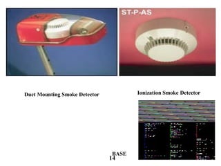
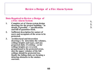
4. Air-conditioning and ventilation
drawings ] To ensure early smoke
detection for the air sucked by the
air-conditioning ... etc hence
special duct smoke detectors must
be employed ( or a continuous air
sample must be drawn for early
smoke detection ). Moreover it
enables the design reviewer to
determine the dimensions and ducts
roots to ensure that it forms no
obstacles similar to the falling slabs.
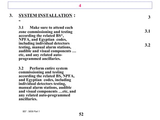
5. A primary design review to the
available fire alarm detectors
distribution.
a. The number and types of the
detectors according to E.S ,
B.S. & NFPA.
b. The fire alarm zones according
to E.S., B.S. & NFPA.
4.
5.
.
67](https://image.slidesharecdn.com/firealarmsystems-171107014314/85/Fire-alarm-systems-67-320.jpg)


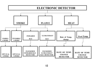
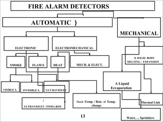
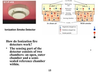
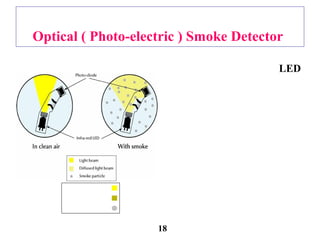
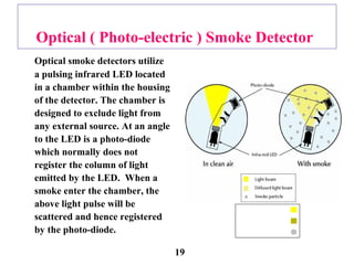
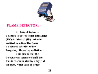
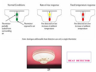
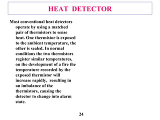
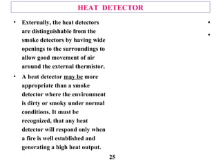
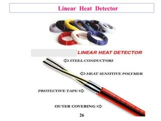
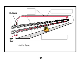
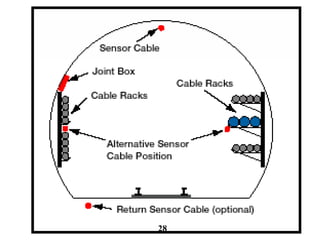
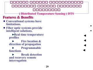
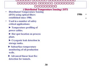
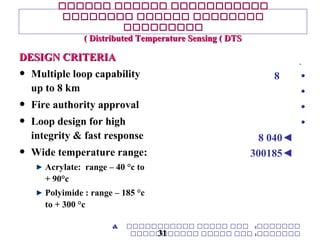
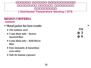
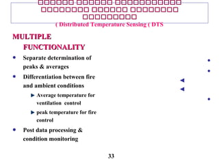
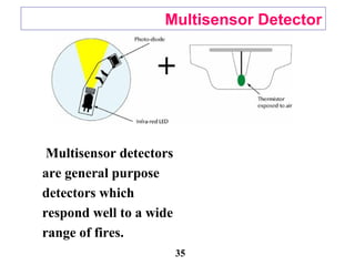
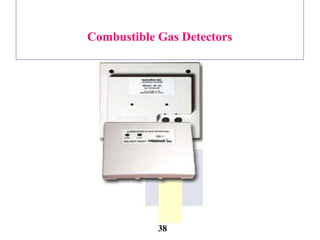
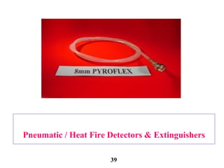
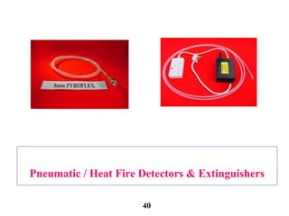
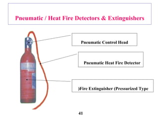
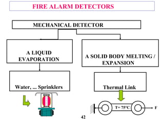
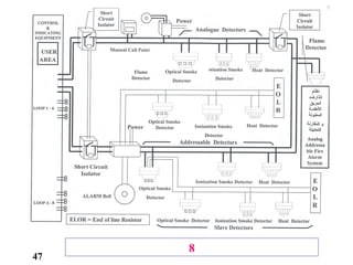
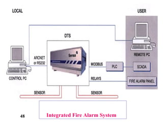
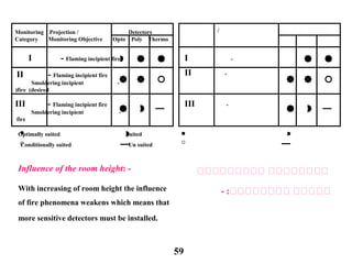
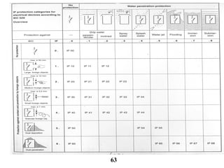
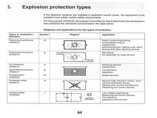
This document discusses different types of fire alarm detectors, including: - Optical smoke detectors that detect smoke particles scattering a light beam. - Ionization smoke detectors that detect changes in air ionization from smoke particles. - Heat detectors that trigger when one thermistor is exposed to higher temperatures than another reference thermistor. - Flame detectors that are sensitive to infrared or ultraviolet radiation from flames. - Linear heat detectors that can detect heat along their entire length to protect large areas. - Distributed temperature sensing uses fiber optic cables to continuously monitor temperature along their length and pinpoint the location of fires.