Downloaded 853 times

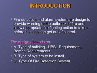
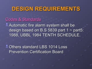
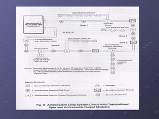
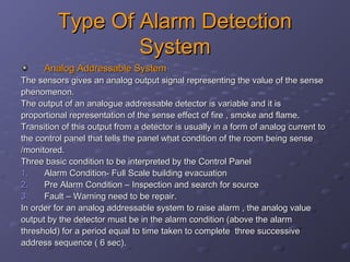
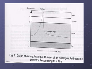
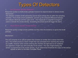


This document discusses fire detection and alarm systems. It covers the design requirements based on building standards, planning the system based on building type and size, selecting the type of coverage needed, configuring zones within the premises, guidelines for zone configuration, types of alarm detection systems including conventional and addressable, and addressing techniques for detectors. The overall purpose is to provide early warning of fires and allow firefighting actions before situations get out of control.