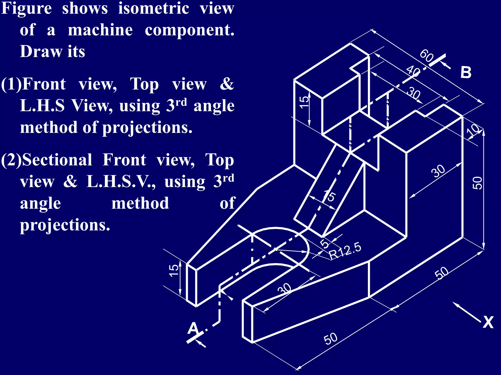
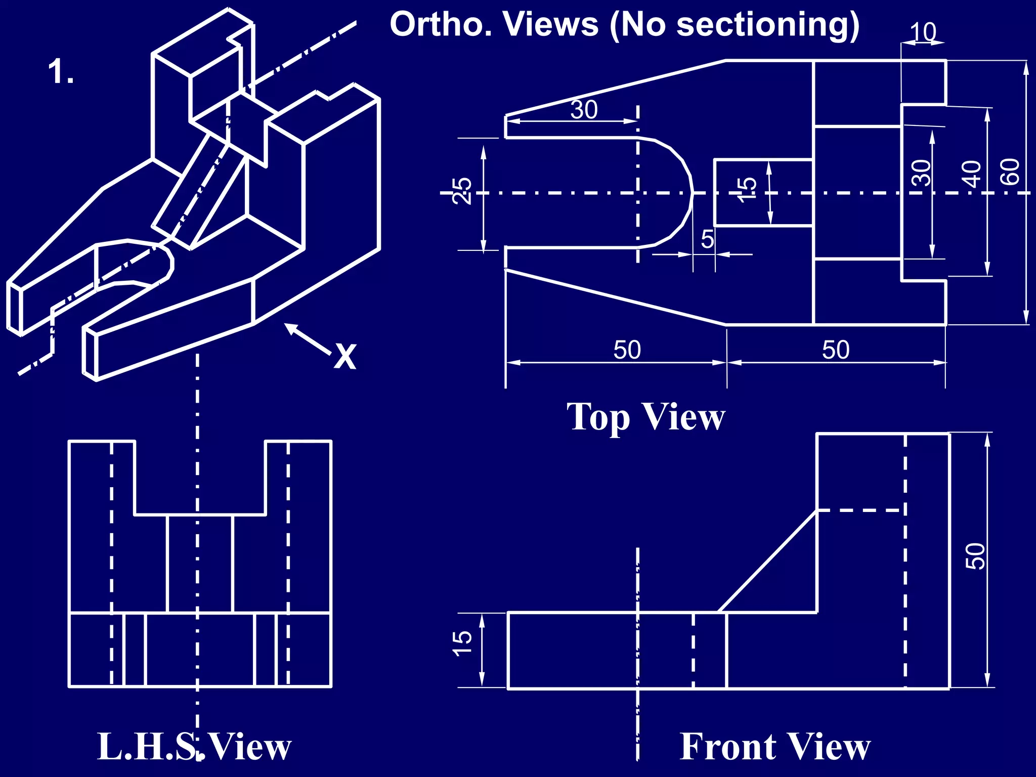
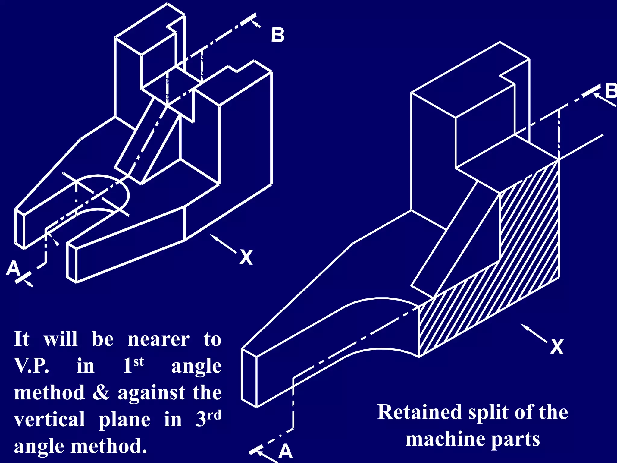
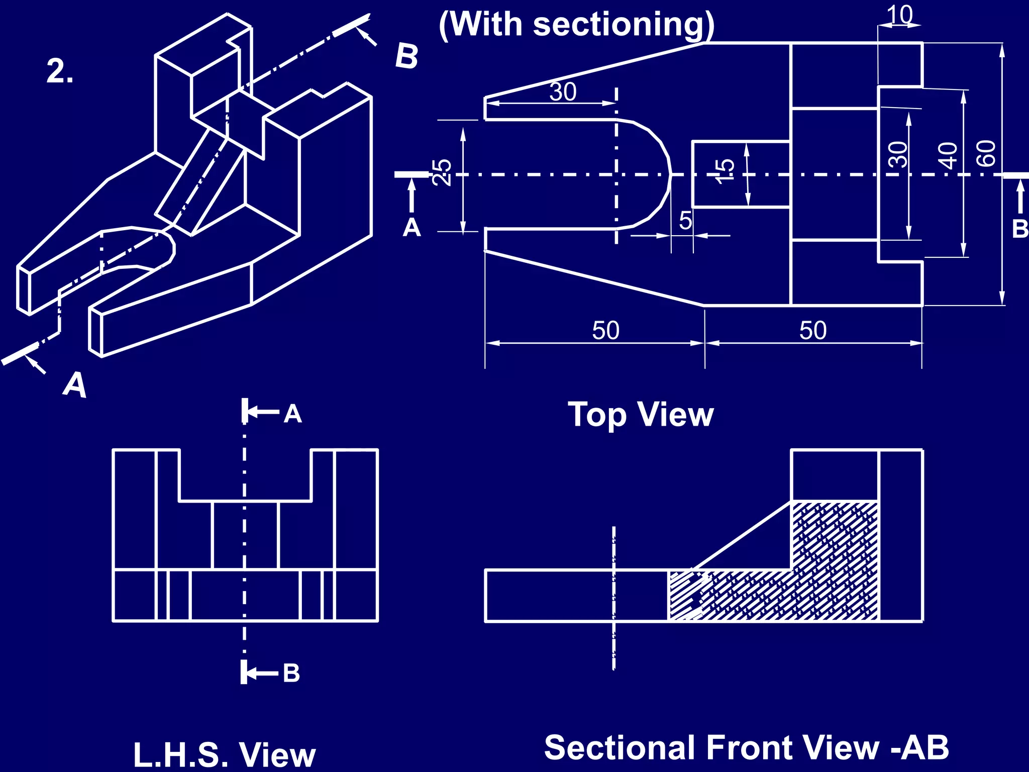
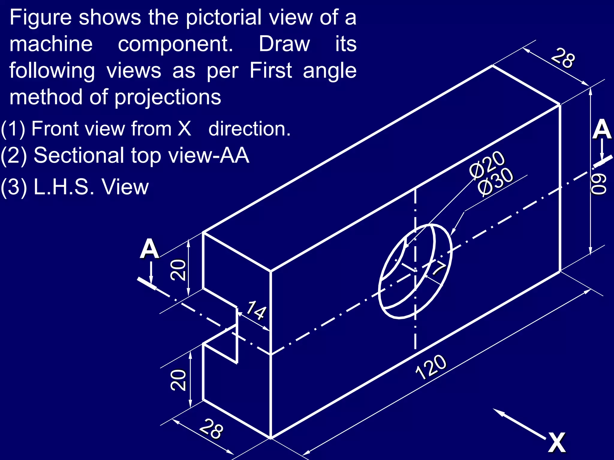
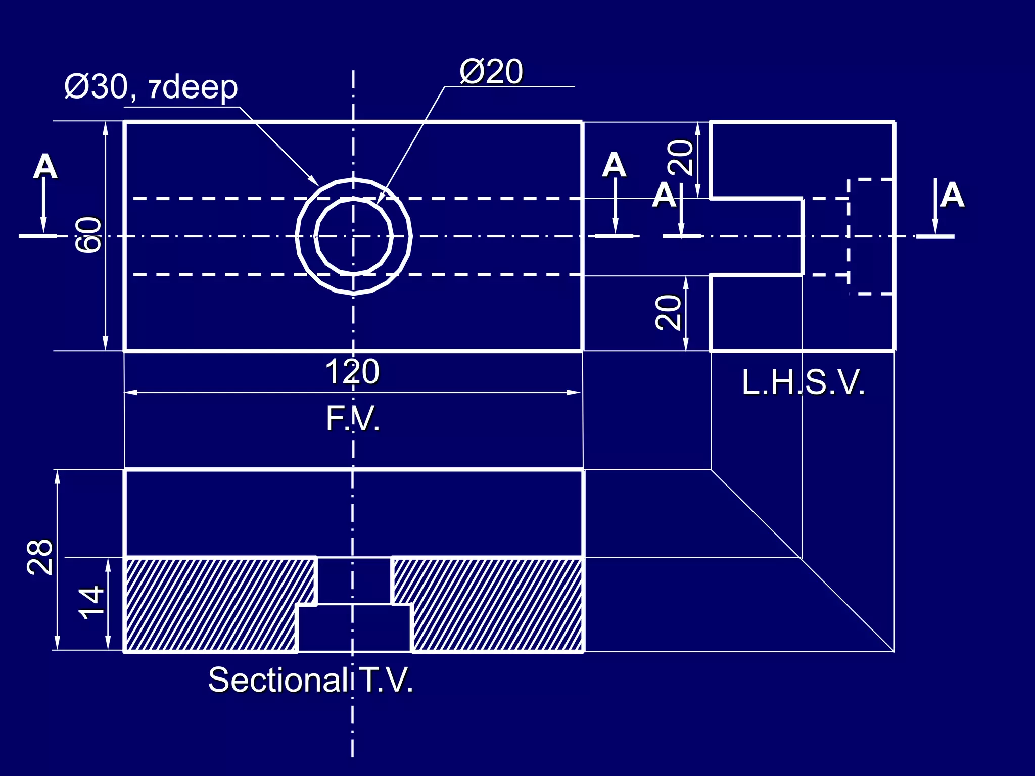
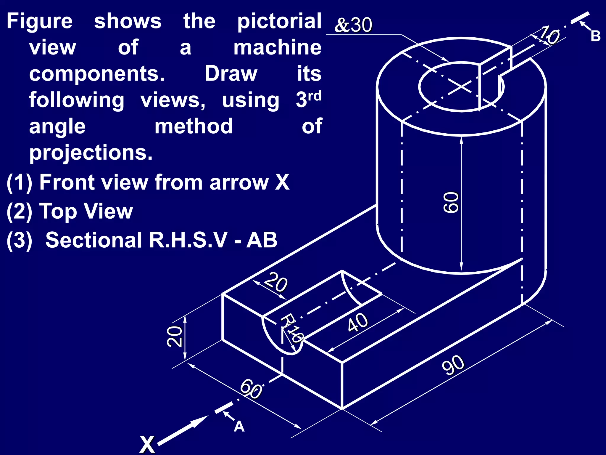
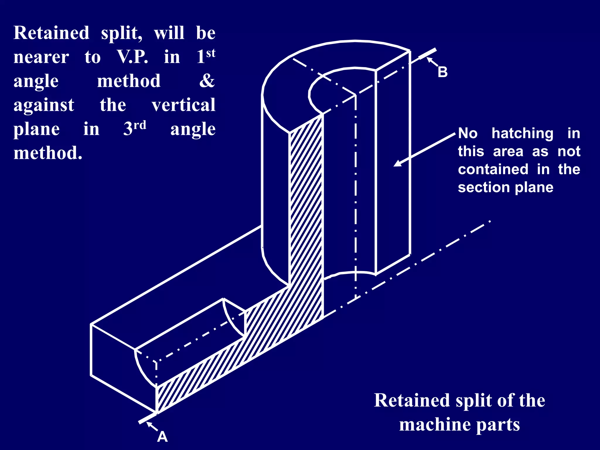
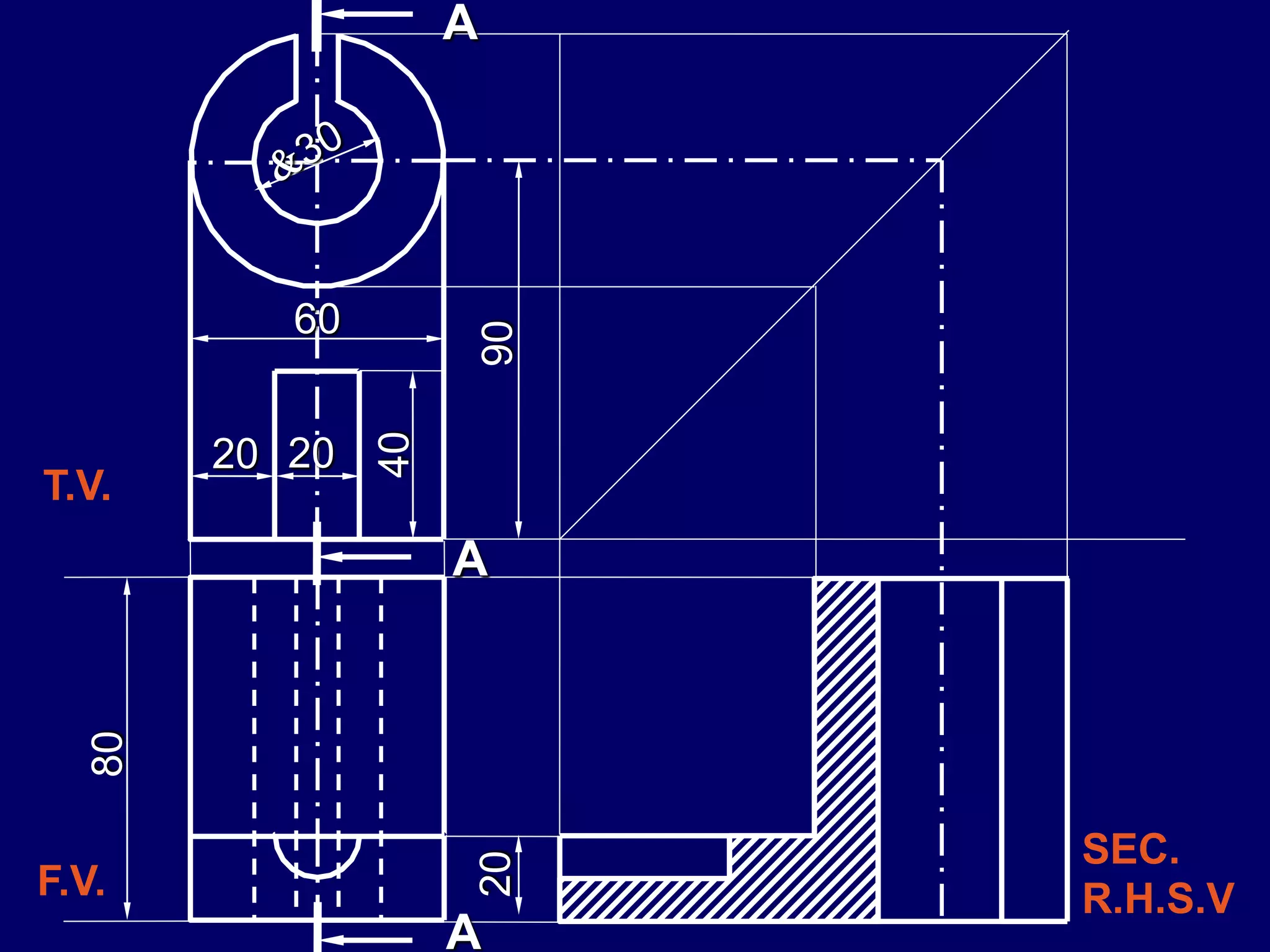
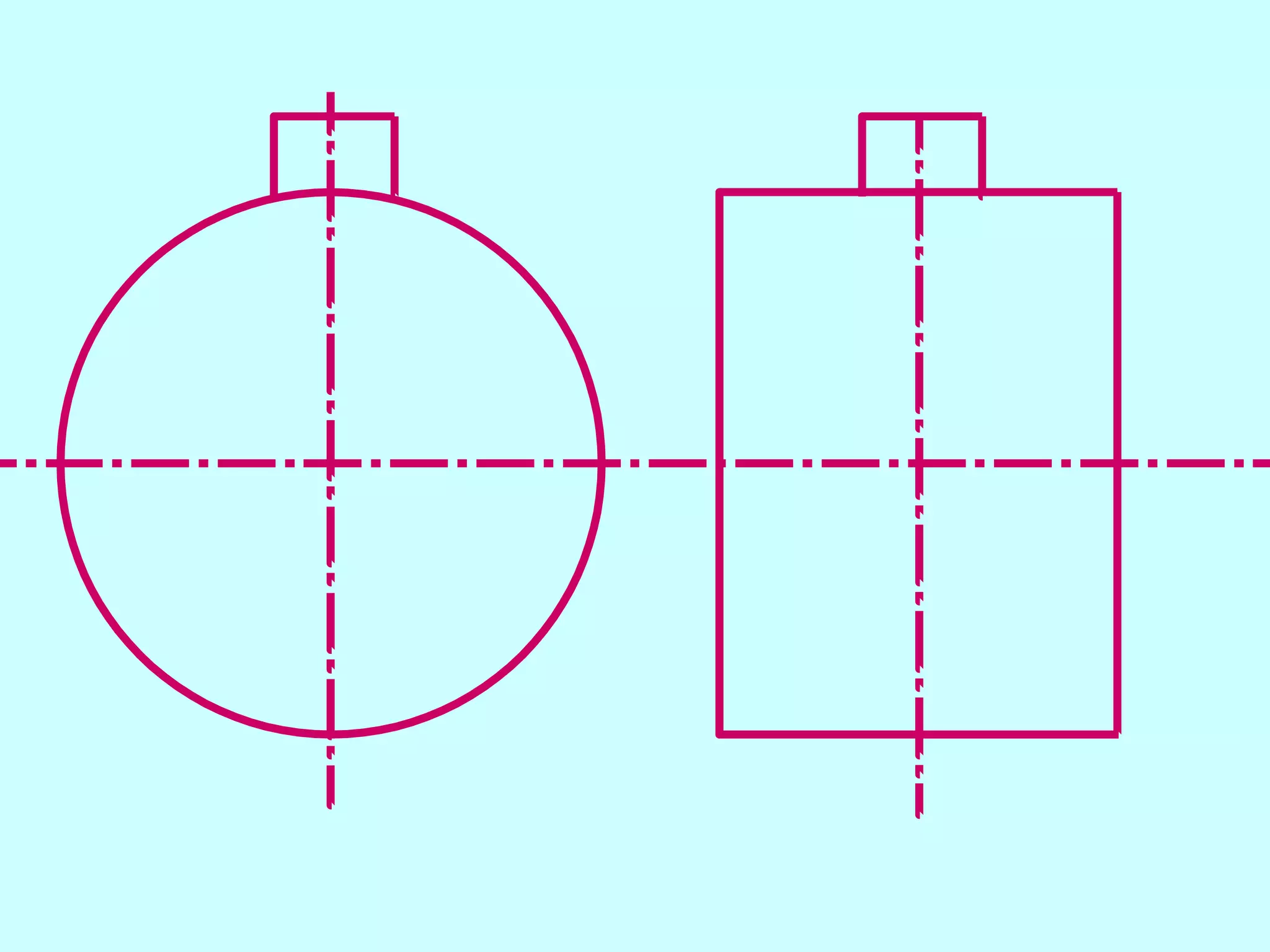
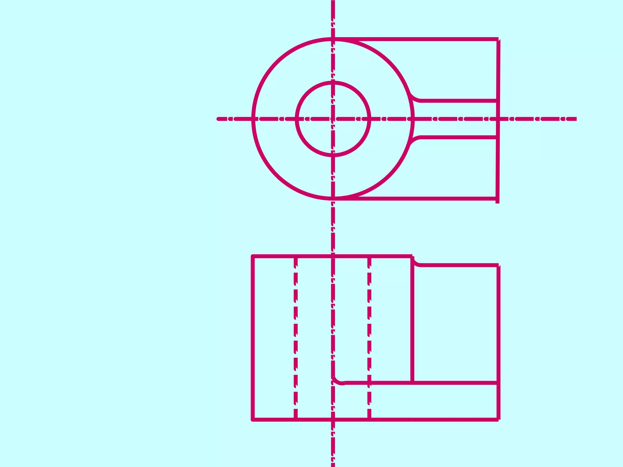
1. The document discusses various types of sectioning that can be applied to machine components in technical drawings, including vertical, horizontal, and normal sections.
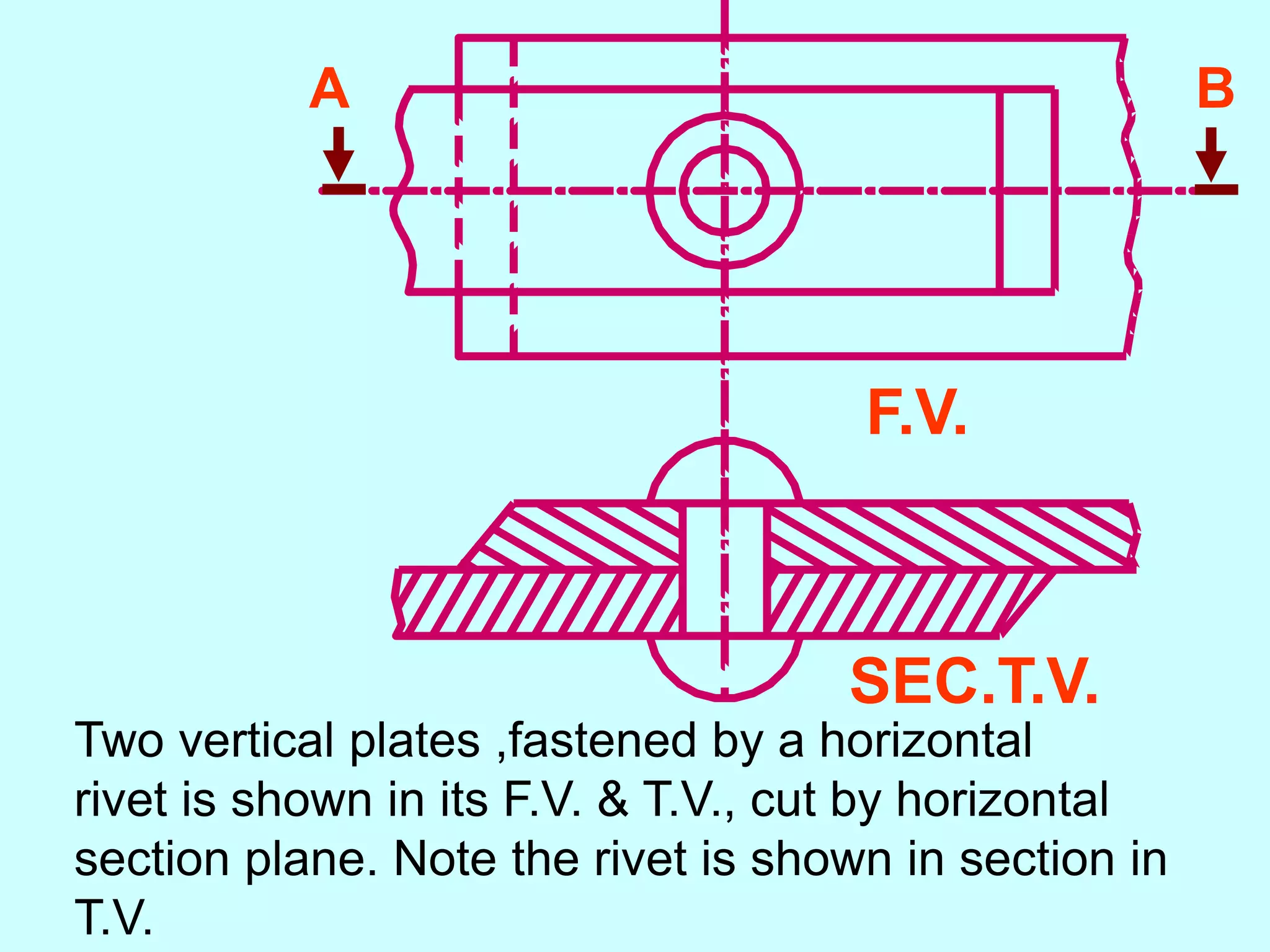
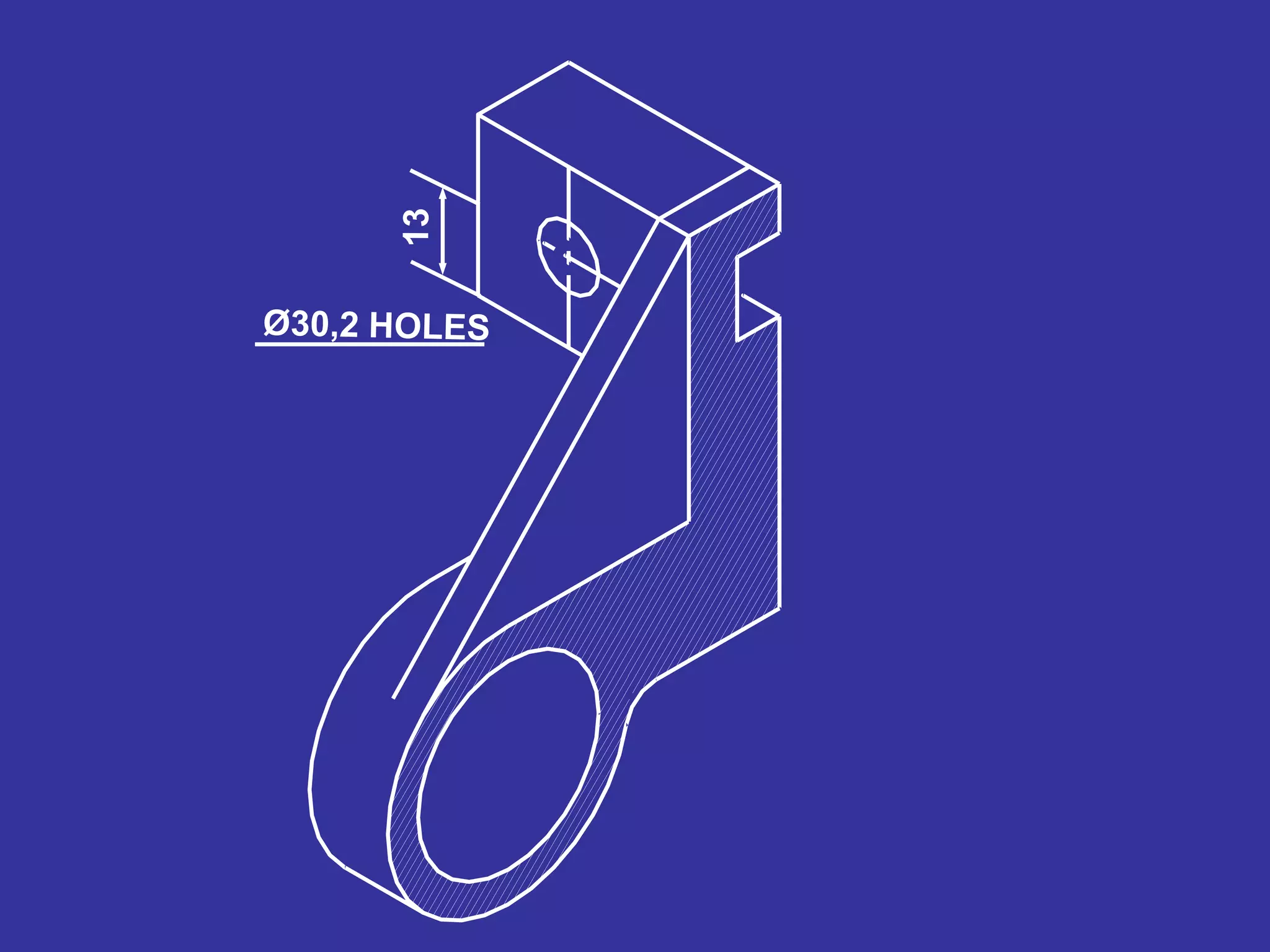
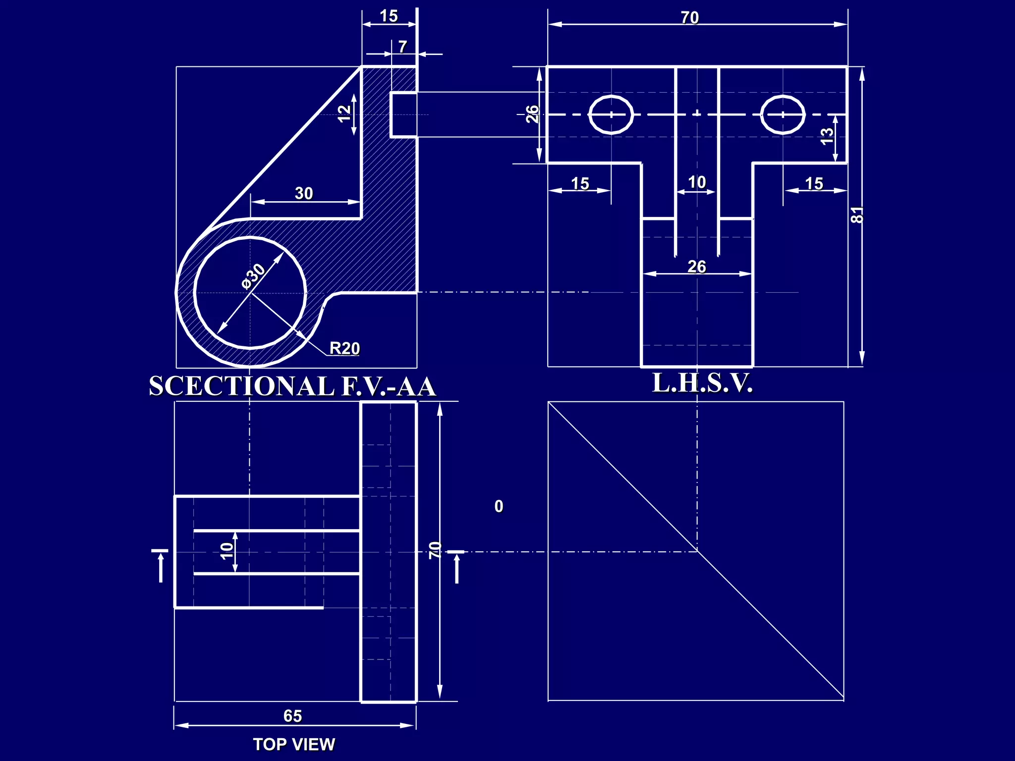
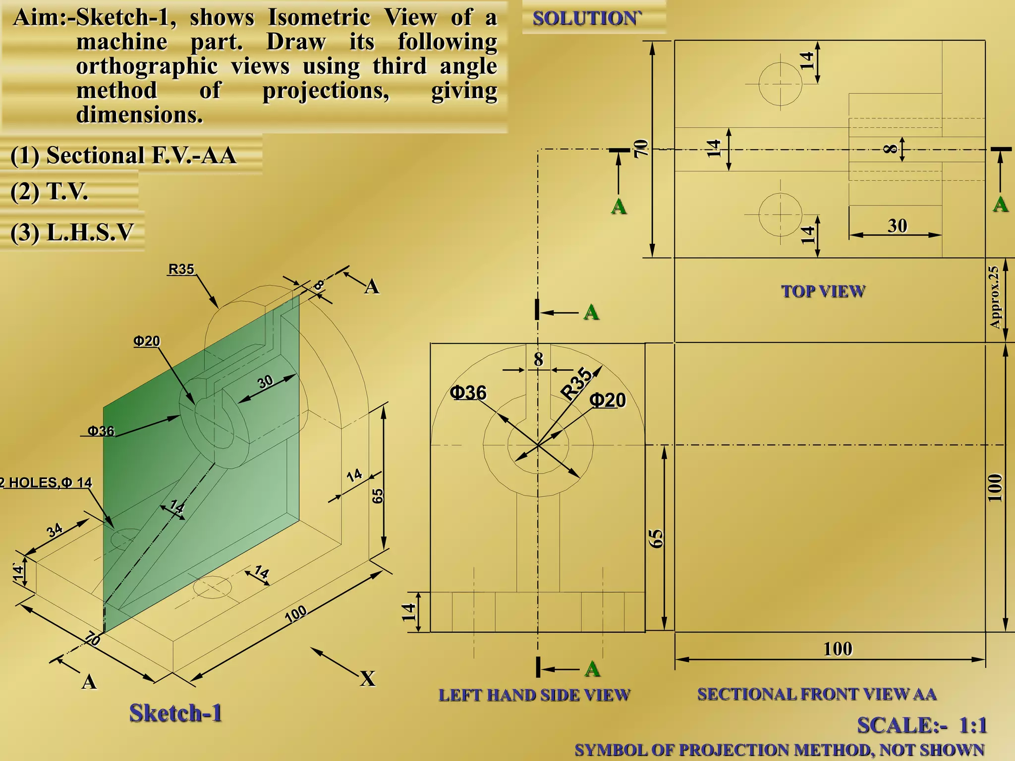
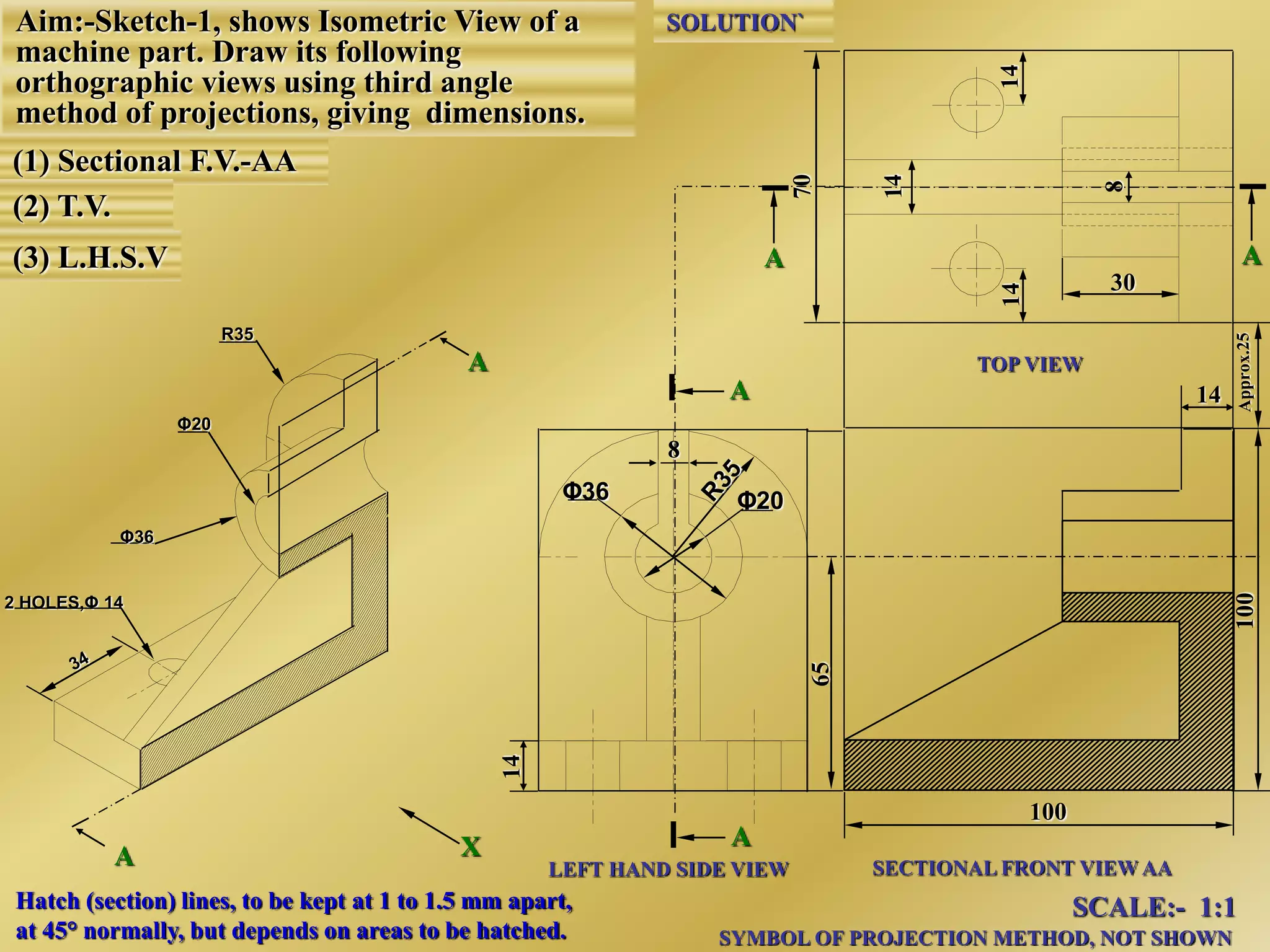
2. It also describes how the sectioning plane and cut component will appear in different views, for example a horizontal section plane will show the cut shape in the top view.
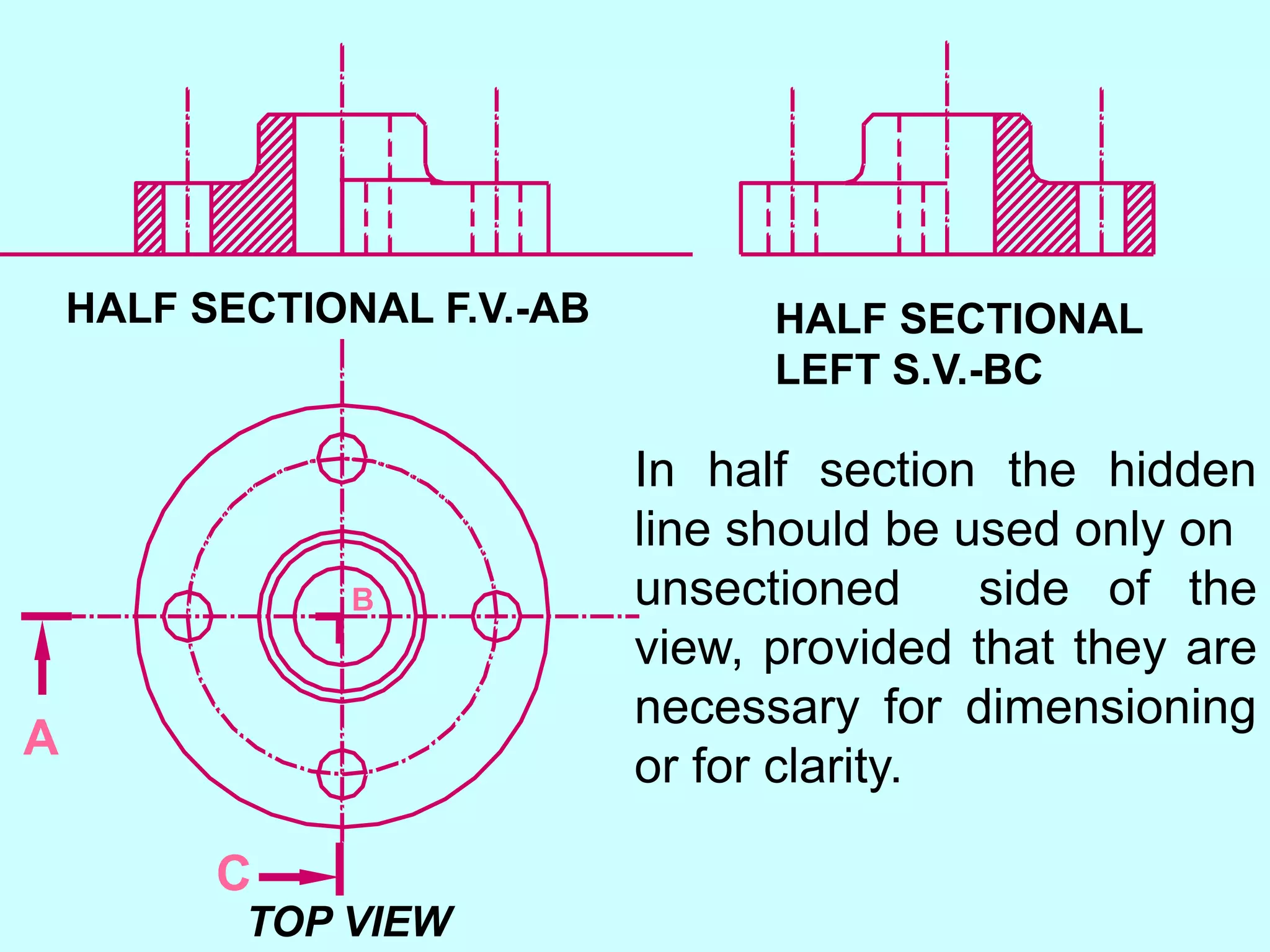
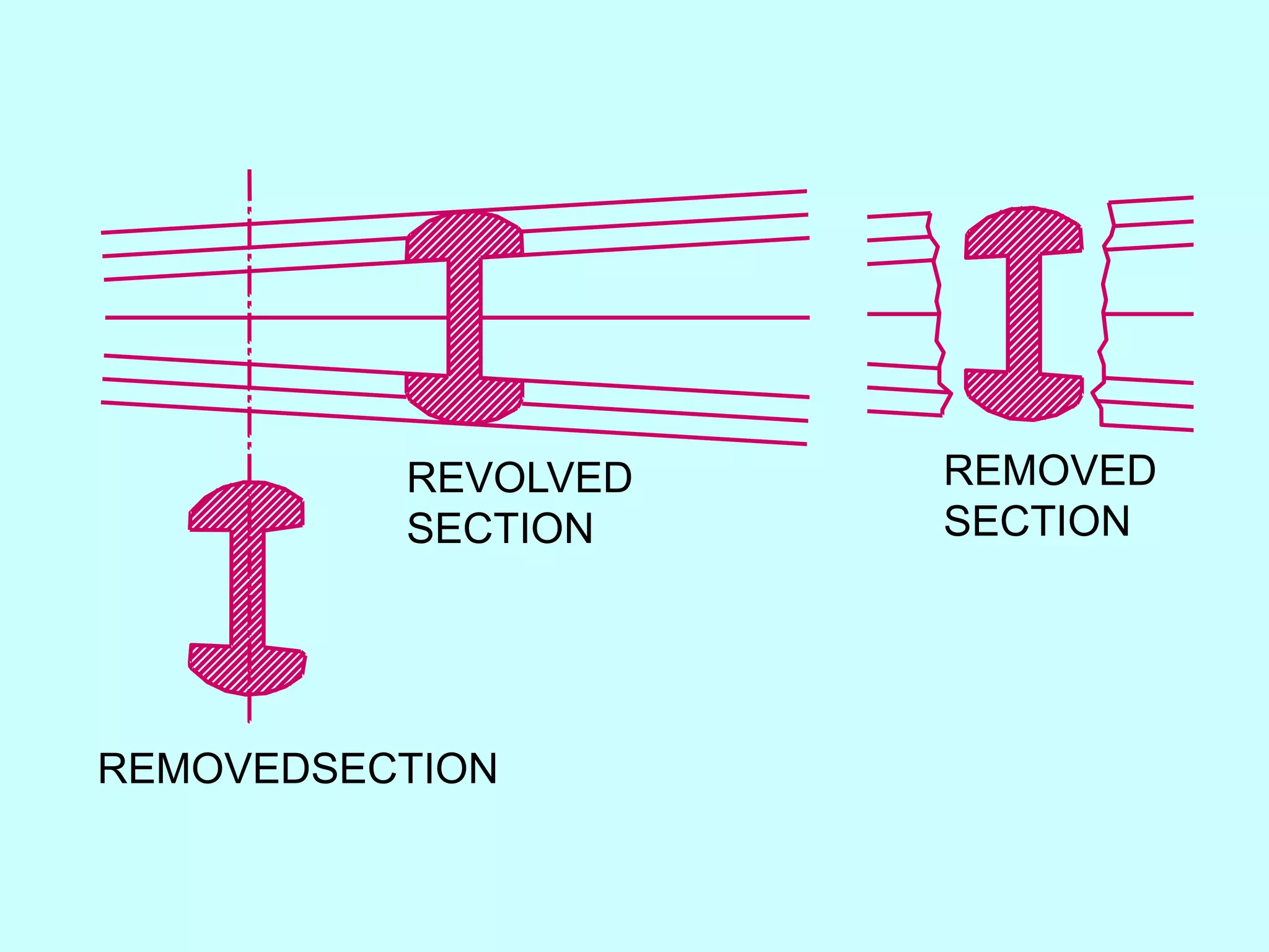
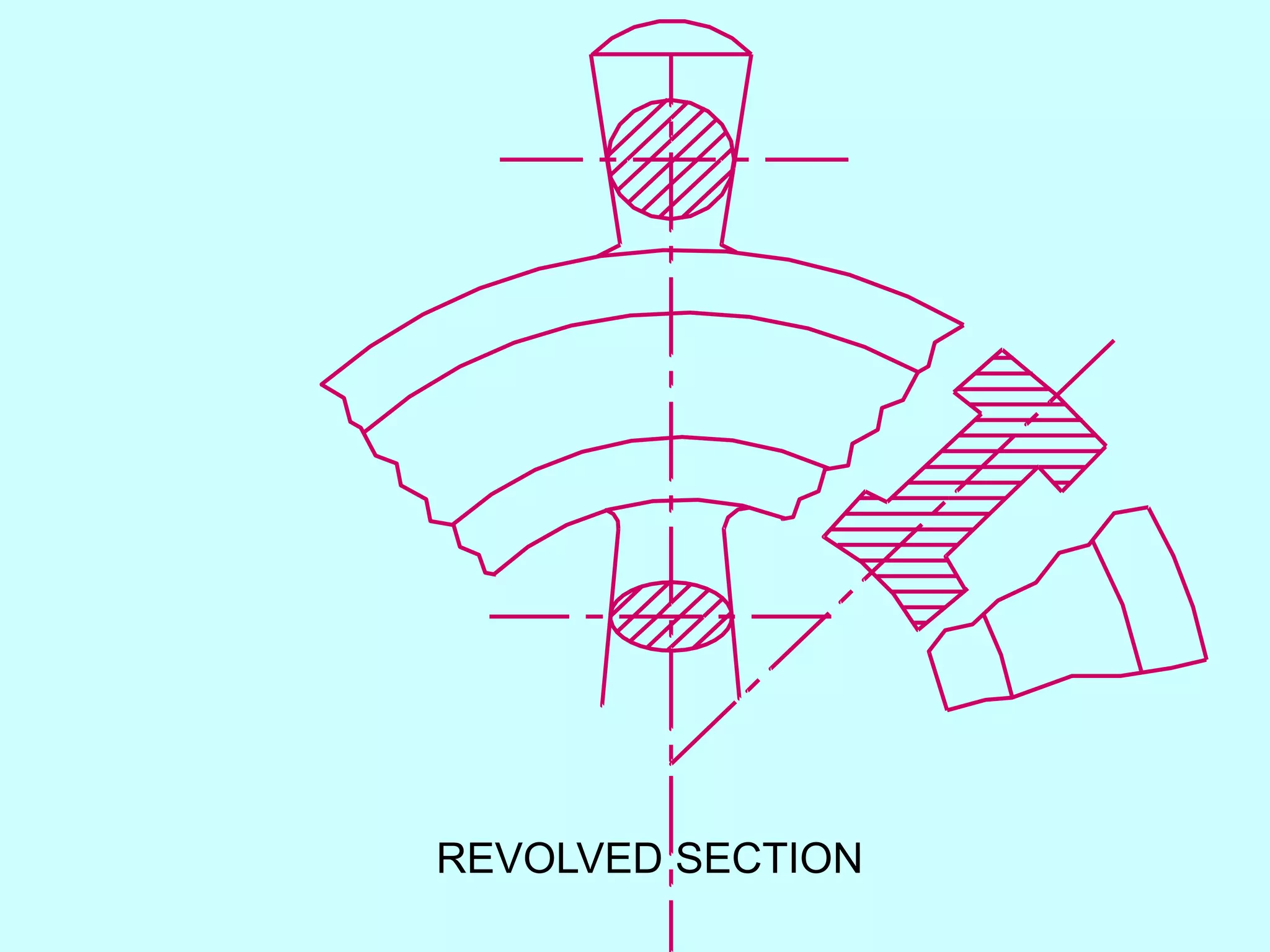
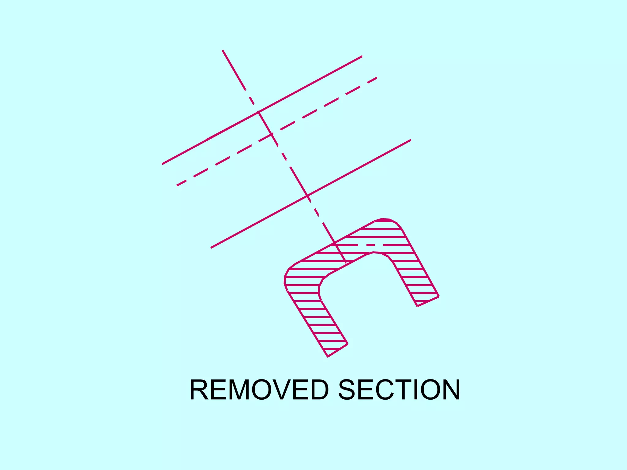
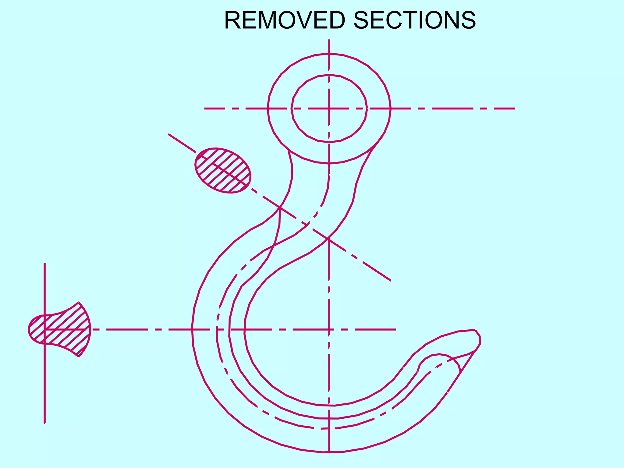
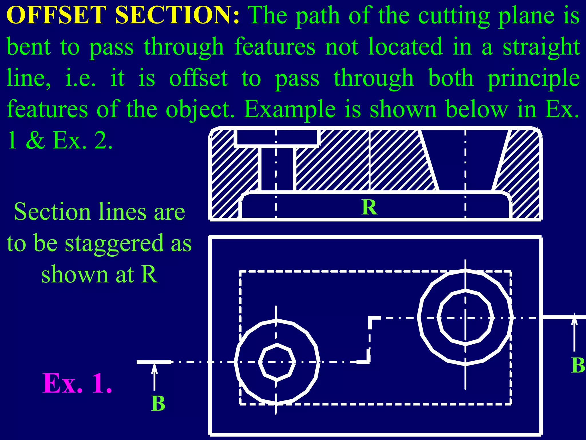
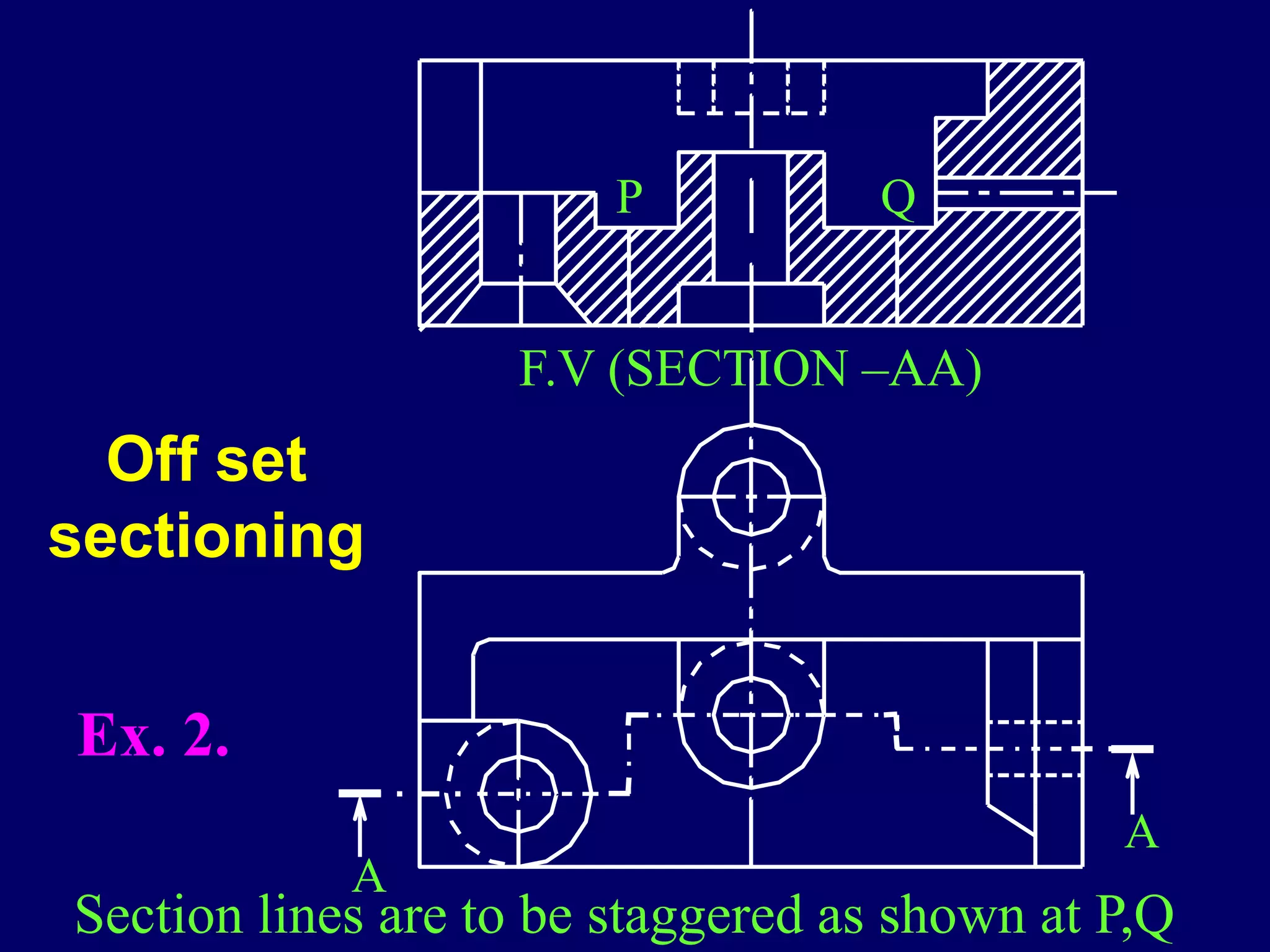
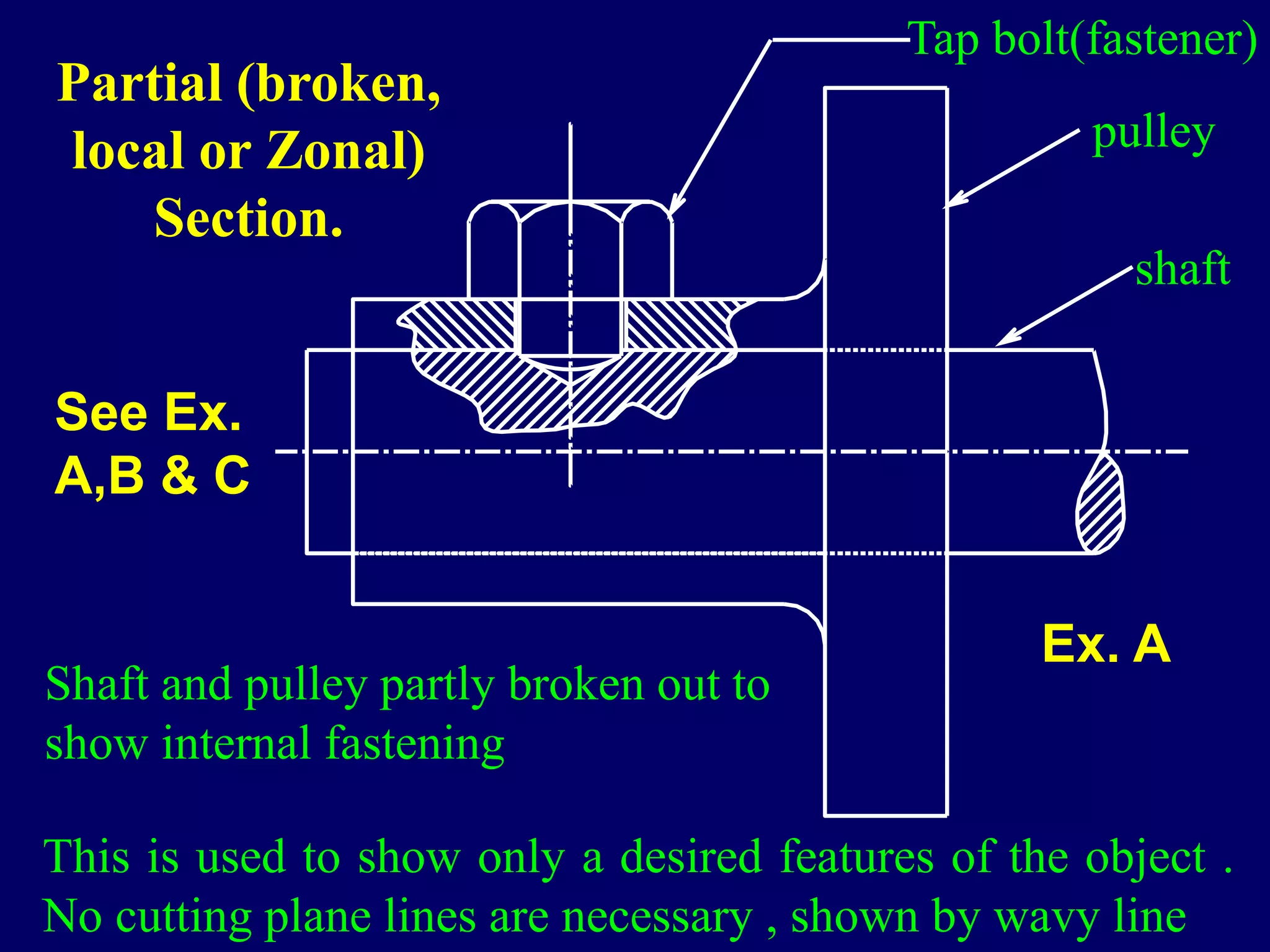
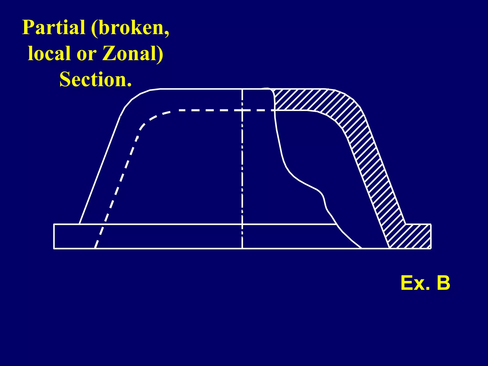
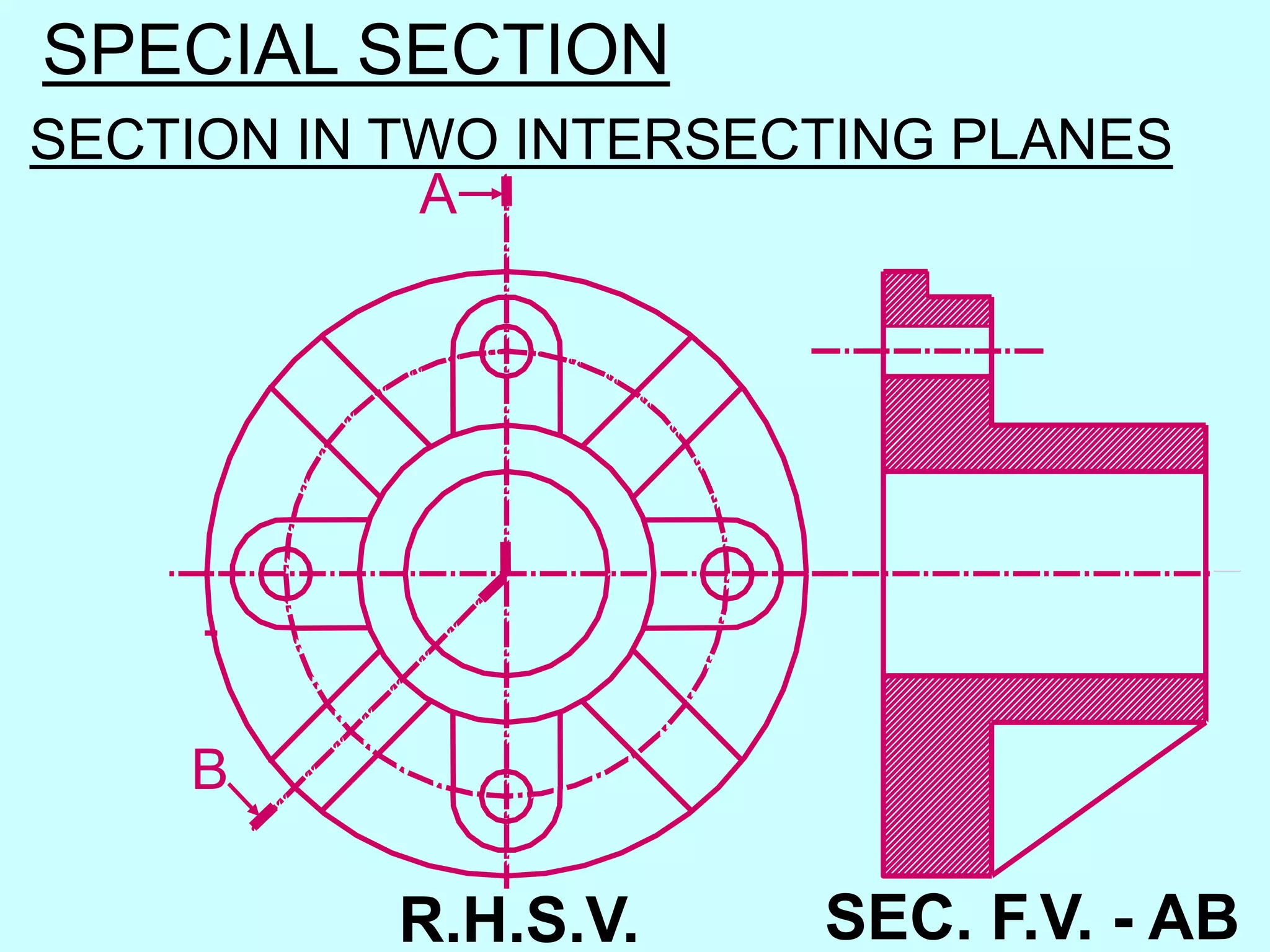
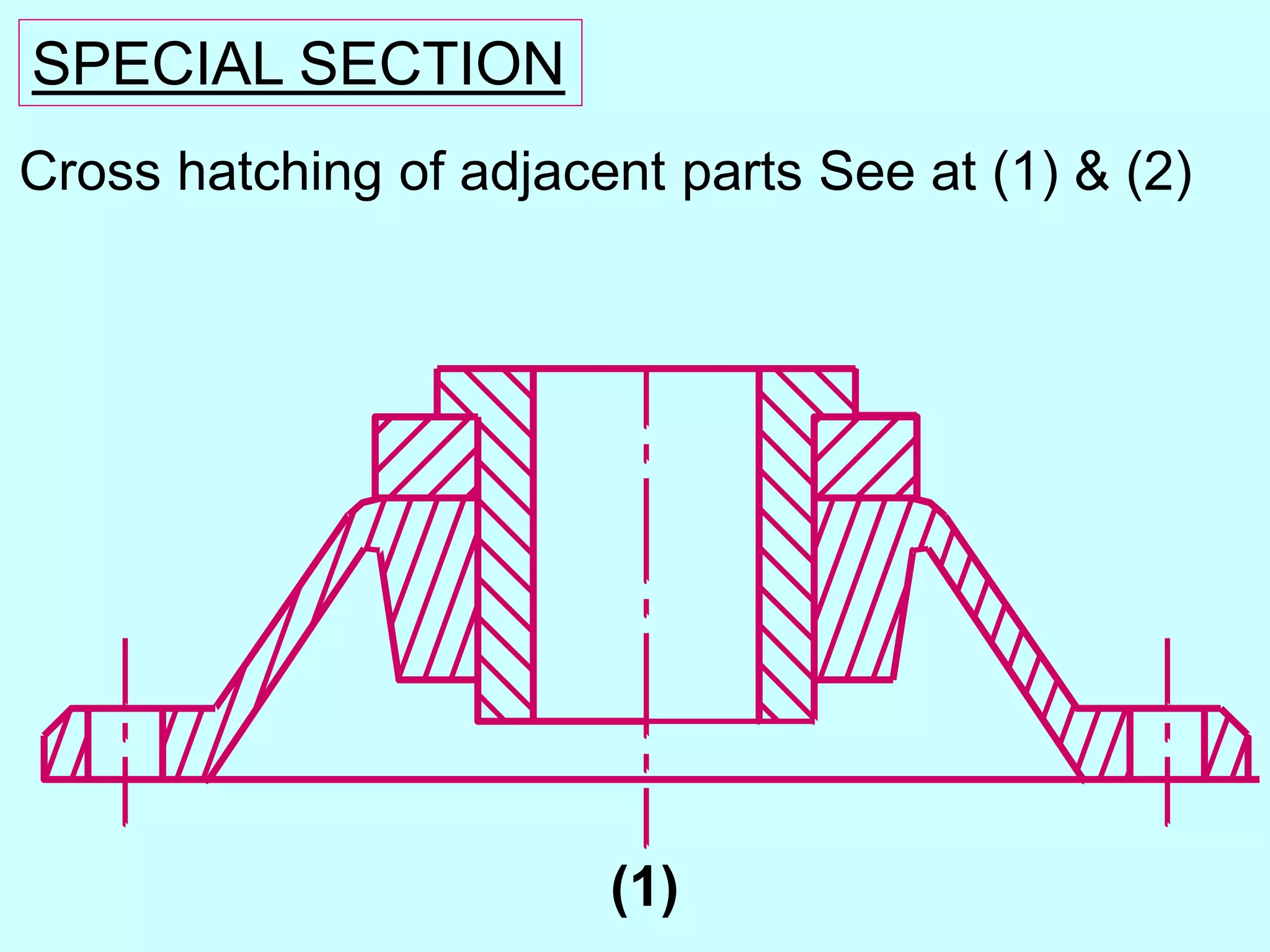
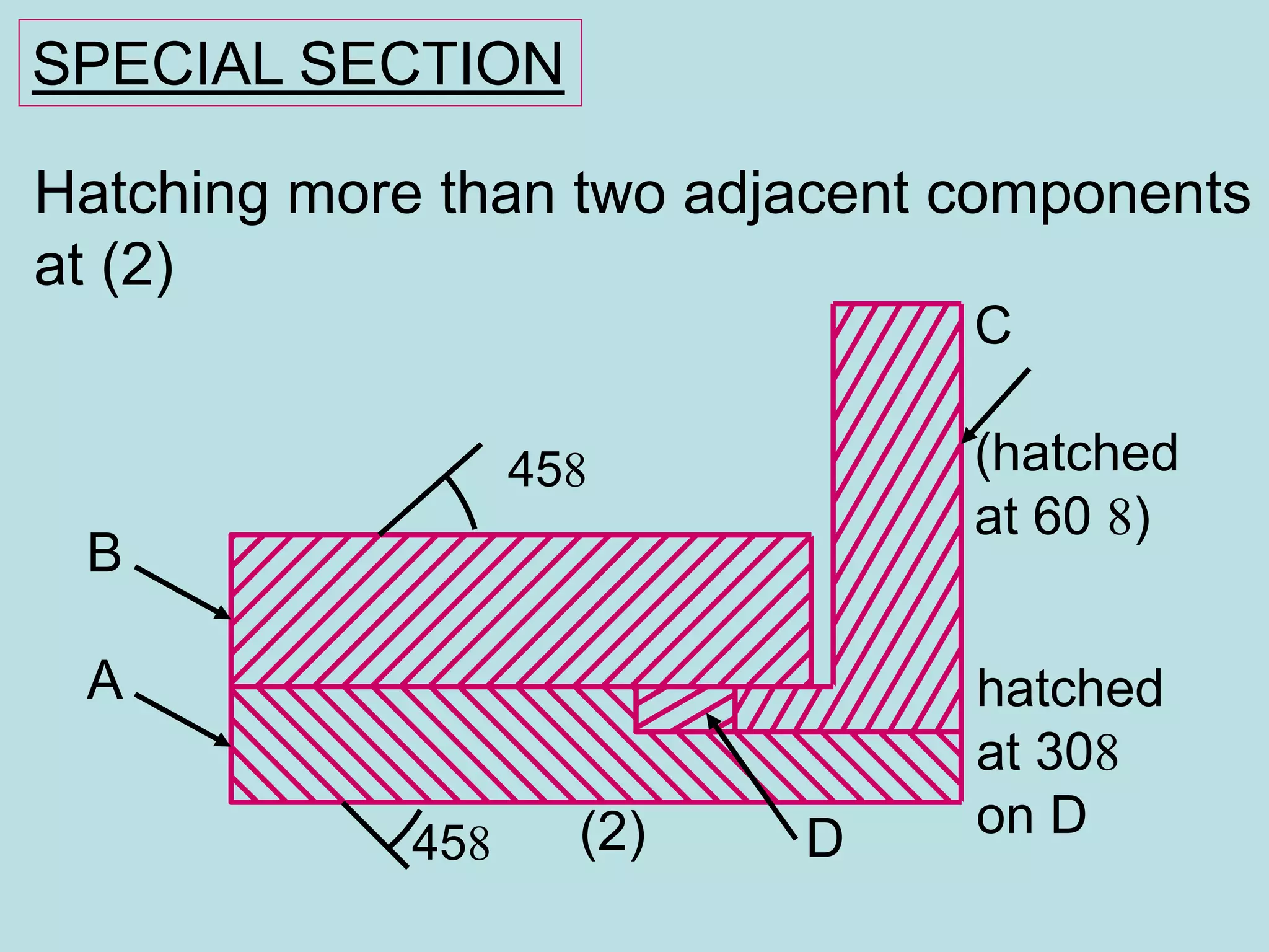
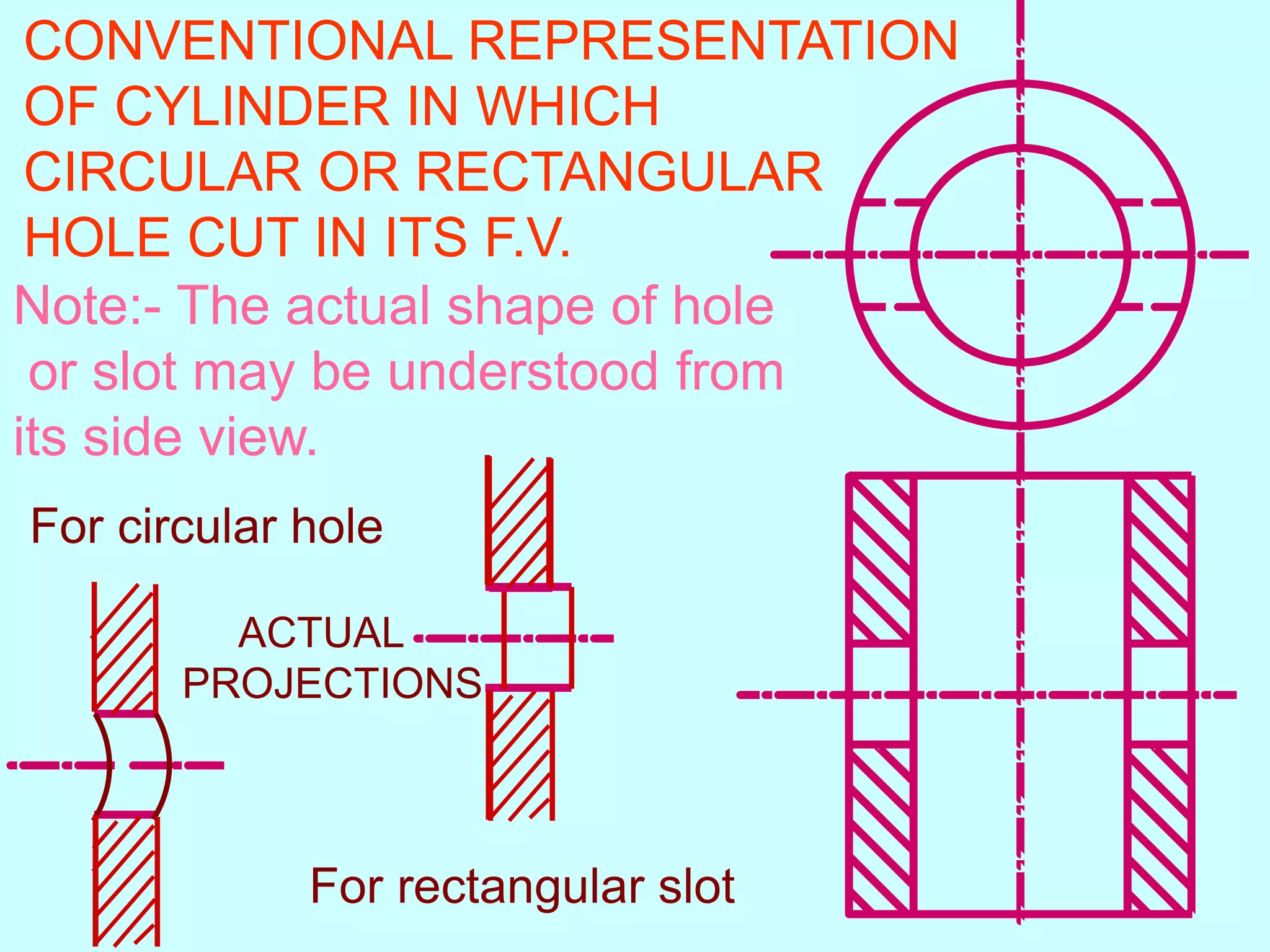
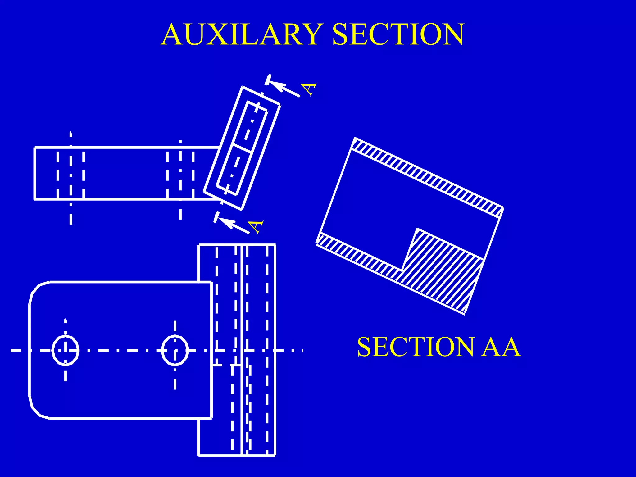
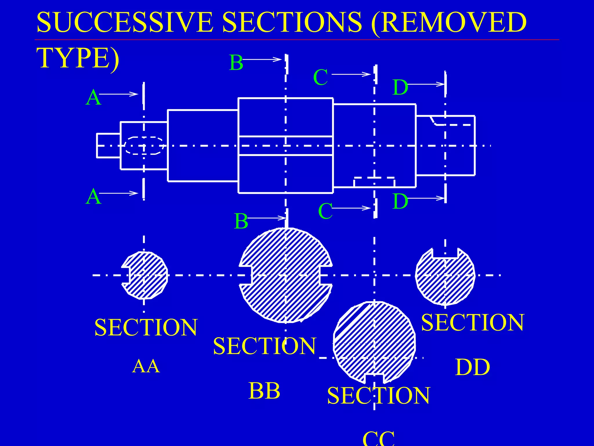
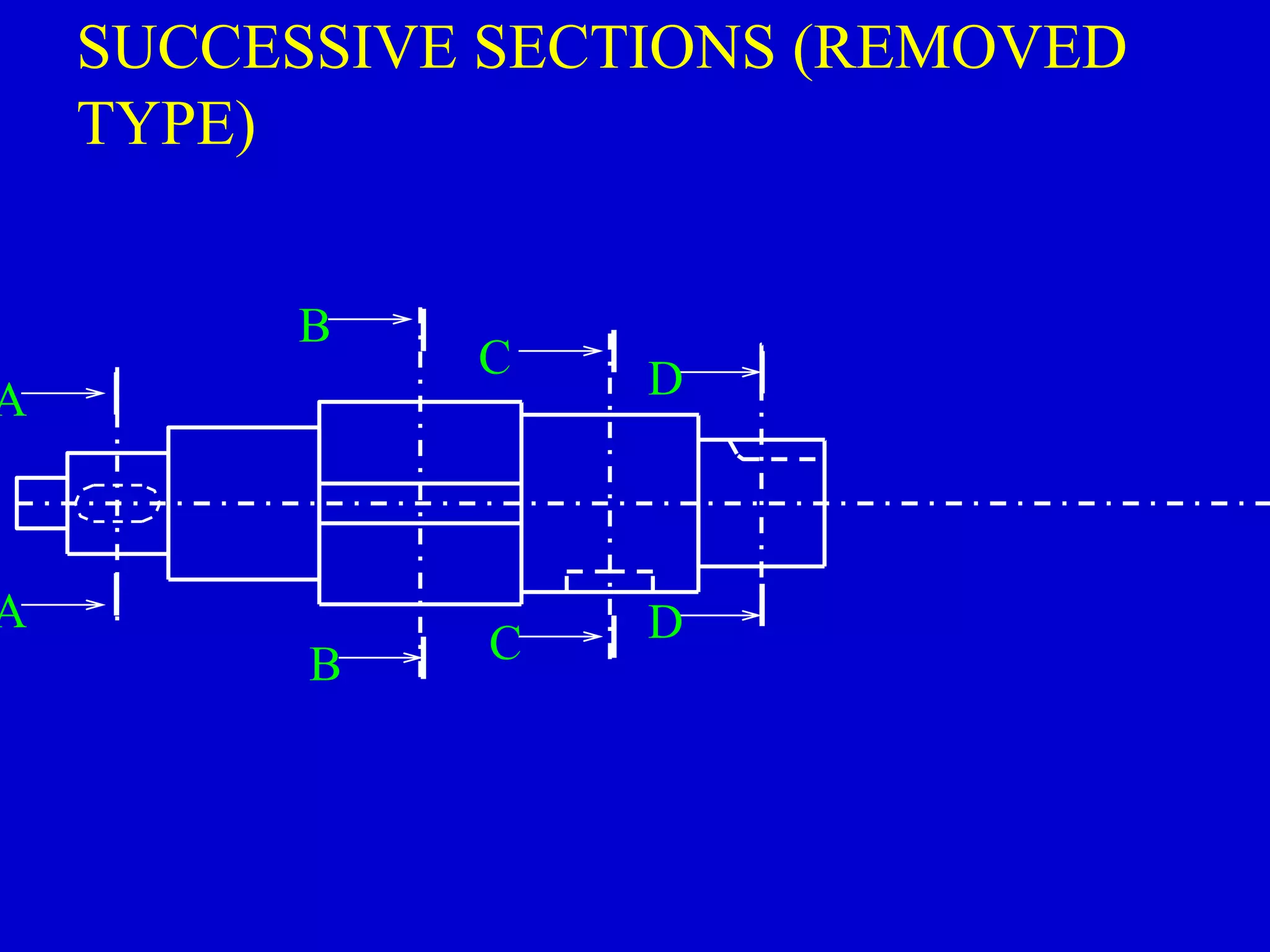
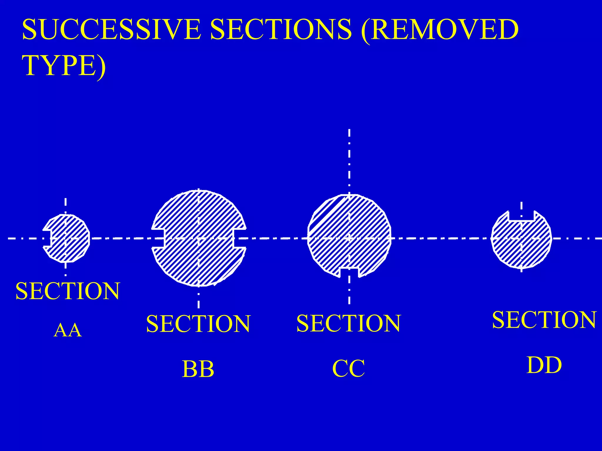
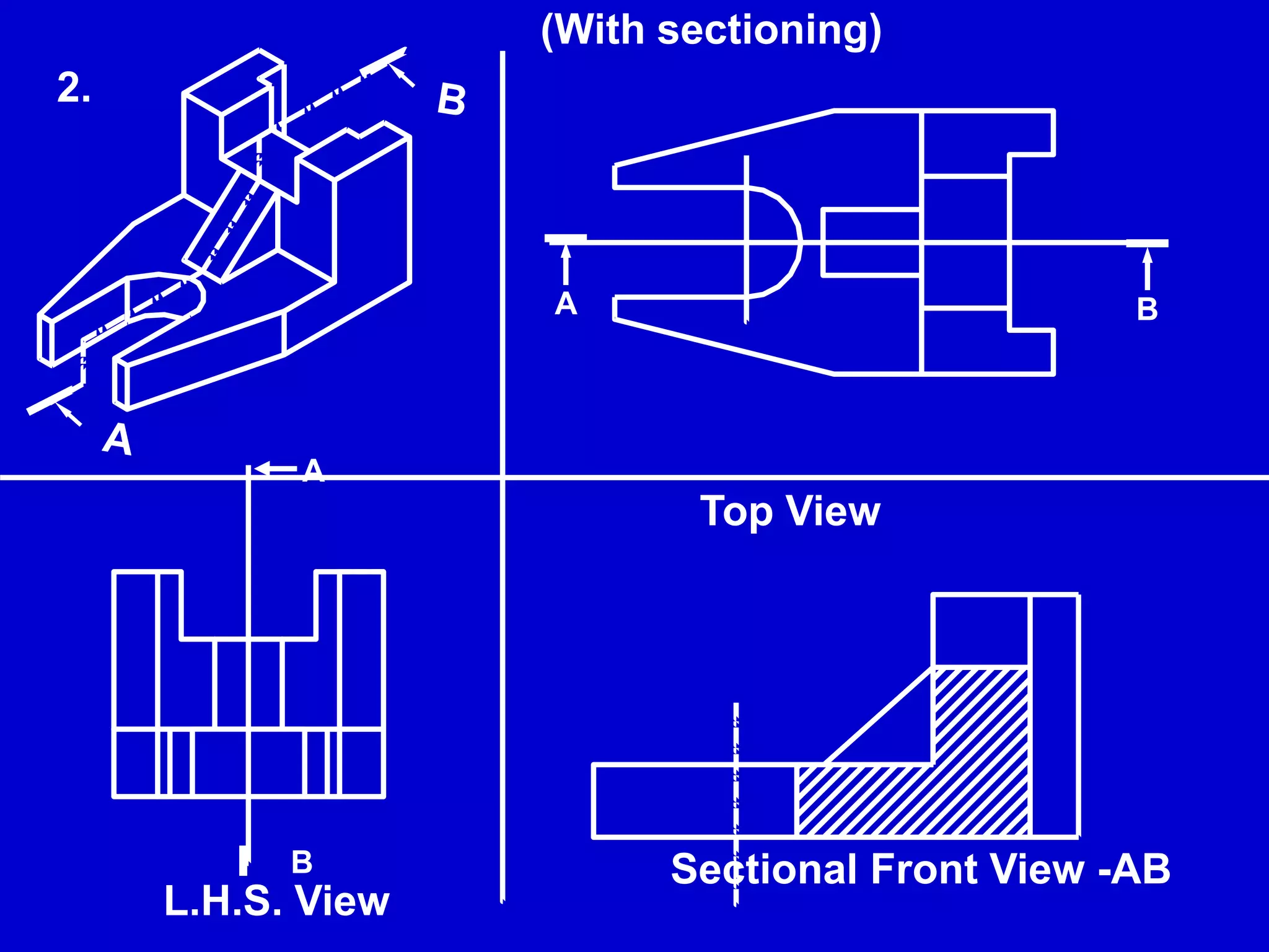
3. Special sectioning techniques are introduced such as half sections, removed sections, revolved sections, and intersecting plane sections. Hatching patterns and cutting plane indications are also covered.