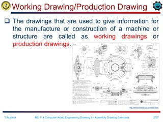
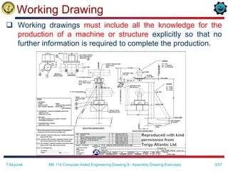
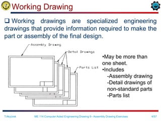
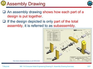
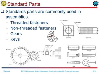
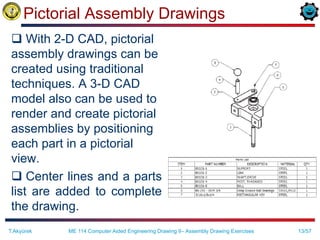
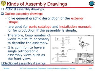
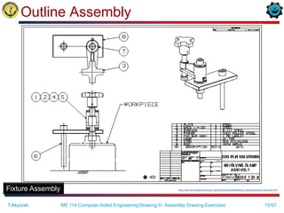
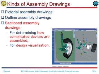
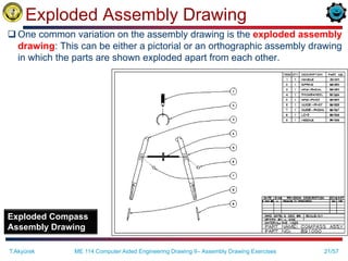
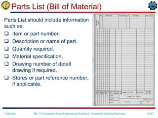
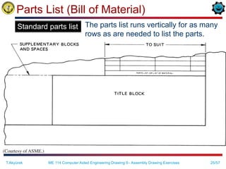
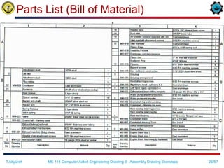
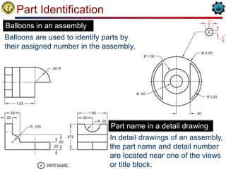
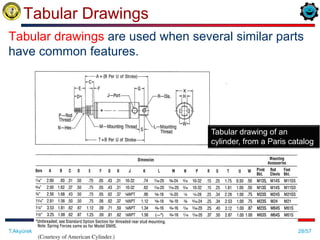
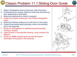
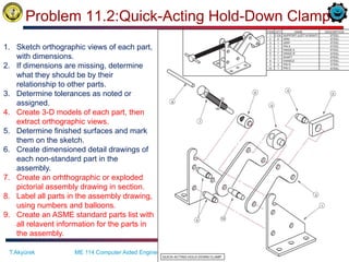
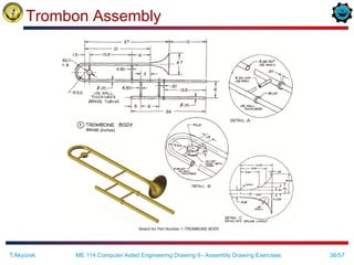
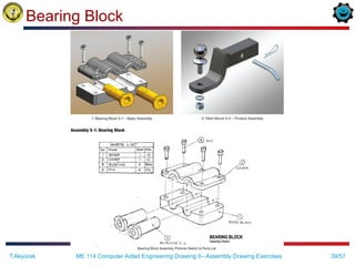
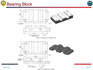
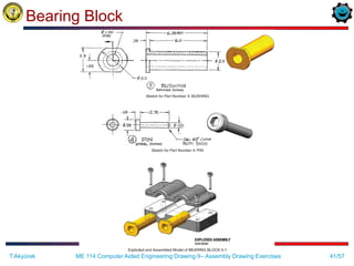
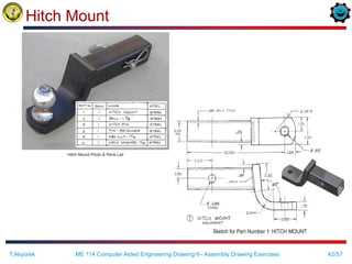
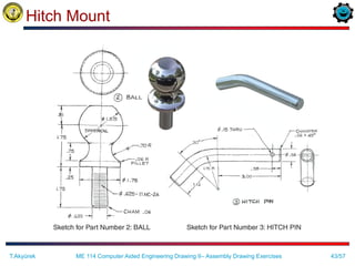
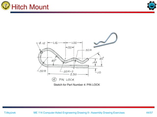
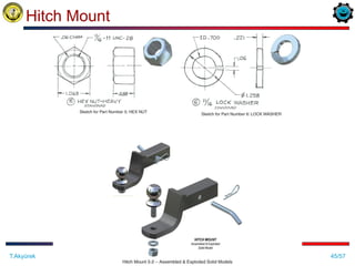
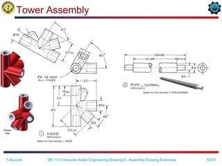
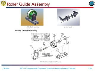
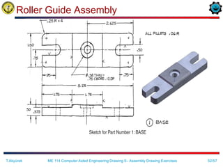
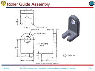
ME 114
Computer Aided Engineering
Drawing - II
Asst.Prof.Dr.Turgut AKYÜREK
Çankaya University, Ankara
Assembly Drawing Exercises
2/57
Working Drawing/Production Drawing
 The drawings that are used to give information for
the manufacture or construction of a machine or
structure are called as working drawings or
production drawings.
T.Akyürek ME 114 Computer Aided Engineering Drawing II– Assembly Drawing Exercises
http://www.linmech.co.uk/detail.html
3/57
Working Drawing
 Working drawings must include all the knowledge for the
production of a machine or structure explicitly so that no
further information is required to complete the production.
T.Akyürek ME 114 Computer Aided Engineering Drawing II– Assembly Drawing Exercises
4/57
Working Drawing
 Working drawings are specialized engineering
drawings that provide information required to make the
part or assembly of the final design.
•May be more than
one sheet.
•Includes
-Assembly drawing
-Detail drawings of
non-standard parts
-Parts list
T.Akyürek ME 114 Computer Aided Engineering Drawing II– Assembly Drawing Exercises
5/57
Assembly Drawing
 An assembly drawing shows how each part of a
design is put together.
 If the design depicted is only part of the total
assembly, it is referred to as subassembly.
http://www.robspencerdesign.co.uk/13912.html
T.Akyürek ME 114 Computer Aided Engineering Drawing II– Assembly Drawing Exercises
6/57
Constructing an Assembly
 Constructing an assembly begins with bringing in a
base component. A base component will be
selected because of its central role in defining the
overall assembly.
 Each successive component brought in needs to be
oriented and located relative to other components
in the assembly.
 Location and orientation is achieved by defining
geometric relations between geometric elements of
a component in the assembly and elements of
components beeing brought in.
T.Akyürek ME 114 Computer Aided Engineering Drawing II– Assembly Drawing Exercises
7/57
Content of Working Drawings for an Assembly
 An assembly or subassembly drawing showing all the
standard and nonstandard parts in a single drawing,
drawn in their operating position
 A parts list or bill of materials, showing
– detail number for each part,
– the quantity needed for a single assembly,
– the description or name of the part,
– catalog number if it is a standard part,
– and the company part number
 A title block
 Detail drawings of each nonstandard part
T.Akyürek ME 114 Computer Aided Engineering Drawing II– Assembly Drawing Exercises
8/57
Assembly Drawing Content
 All the parts drawn in their operating position
 A parts list or bill of materials, showing
– detail number for each part,
– the quantity needed for a single assembly,
– the description or name of the part,
– catalog number if it is a standard part,
– and the company part number
 Leader lines with balloons, assigning each part a detail
number, in sequential order and keyed to the list of parts
in the parts list
 Machning and assembly operations and critical
dimensions related the functions.
T.Akyürek ME 114 Computer Aided Engineering Drawing II– Assembly Drawing Exercises
9/57
Standard Parts
 Standards parts are commonly used in
assemblies.
– Threaded fasteners
– Non-threaded fasteners
– Gears
– Keys
T.Akyürek ME 114 Computer Aided Engineering Drawing II– Assembly Drawing Exercises
10/57
Kinds of Assembly Drawings
 Pictorial assembly drawings
 Outline assembly drawings
 Sectioned assembly drawings
T.Akyürek ME 114 Computer Aided Engineering Drawing II– Assembly Drawing Exercises
11/57
Kinds of Assembly Drawings
Pictorial assembly drawings
These drawings are very useful to indicate the method of
assembly, and are often used in technical manuals.
Outline assembly drawings
Sectioned assembly drawings
T.Akyürek ME 114 Computer Aided Engineering Drawing II– Assembly Drawing Exercises
A Model Created as an
Illustration for Maintenance
Handbooks
12/57
Pictorial Assembly Drawings
 Pictorial assembly
drawings give general
graphic description of each
part and uses center lines
to show how the parts are
assembled.
 The pictorial assembly is
normally an isometric view
and is used in installation
and maintenance manuals.
T.Akyürek ME 114 Computer Aided Engineering Drawing II– Assembly Drawing Exercises
13/57
Pictorial Assembly Drawings
 With 2-D CAD, pictorial
assembly drawings can be
created using traditional
techniques. A 3-D CAD
model also can be used to
render and create pictorial
assemblies by positioning
each part in a pictorial
view.
 Center lines and a parts
list are added to complete
the drawing.
T.Akyürek ME 114 Computer Aided Engineering Drawing II– Assembly Drawing Exercises
14/57
Kinds of Assembly Drawings
 Pictorial assembly drawings
 Outline assembly drawings
– give general graphic description of the exterior
shape.
– are used for parts catalogs and installation manuals,
or for production if the assembly is simple.
T.Akyürek ME 114 Computer Aided Engineering Drawing II– Assembly Drawing Exercises
– Therefore, keep number of
views minimum necessary
to describe the assembly.
– It is common to have a
single orthographic
assembly view, such as
the front view.
Sectioned assembly drawings
15/57
Outline Assembly
http://odin.me.memphis.edu/ugs_docs/NX3/draftingeff/drawing_types/inprocess_drawings.html
Fixture Assembly
T.Akyürek ME 114 Computer Aided Engineering Drawing II– Assembly Drawing Exercises
16/57
Kinds of Assembly Drawings
Pictorial assembly drawings
Outline assembly drawings
Sectioned assembly
drawings
– For determining how
complicated devices are
assembled,
– For design visualization.
T.Akyürek ME 114 Computer Aided Engineering Drawing II– Assembly Drawing Exercises
17/57
Sectioned Assembly Drawings
 Sectioned assembly drawings give general
graphic description of the interior shape by
passing a cutting plane through all or part of
the assembly.
The sectioned assembly is usually a
multiview drawing of all the parts, with one
view in full section (or half section, or broken-
out section etc.).
T.Akyürek ME 114 Computer Aided Engineering Drawing II– Assembly Drawing Exercises
18/57
Sectioned Assembly Drawings
 Reminder on section views:
–Standard parts, such as fasteners, dowels, pins,
bearings, and gears, and nonstandard parts, such
as shafts, are not sectioned; they are drawn
showing all their exterior features.
– Adjacent parts in section are lined at different
angles, using the cast iron or other type of symbol.
–Thin parts, such as gaskets, are shown solid black.
T.Akyürek ME 114 Computer Aided Engineering Drawing II– Assembly Drawing Exercises
19/57
Sectioned Assembly
Piston
http://www.confident-instruments.com/3DModeling.htm
T.Akyürek ME 114 Computer Aided Engineering Drawing II– Assembly Drawing Exercises
20/57
Sectioned Assembly
Sprocket http://jpengineering.blogspot.com/2011/04/sprocket-sectioned-assembly.html
T.Akyürek ME 114 Computer Aided Engineering Drawing II– Assembly Drawing Exercises
21/57
Exploded Assembly Drawing
 One common variation on the assembly drawing is the exploded assembly
drawing: This can be either a pictorial or an orthographic assembly drawing
in which the parts are shown exploded apart from each other.
Exploded Compass
Assembly Drawing
T.Akyürek ME 114 Computer Aided Engineering Drawing II– Assembly Drawing Exercises
22/57
Creating Assembly Drawings
 How to create an assembly drawing?
–An assembly drawing is produced by
tracing the needed views from the detail
drawings, or by creating the drawing from
scratch.
–With 2-D CAD, it is possible to copy detail
views, then place them on the assembly
drawing.
–With 3-D models, simply assemble all the
models, then determine the line of sight to
extract the needed assembly view (recall the
video at the beginning of the course).
T.Akyürek ME 114 Computer Aided Engineering Drawing II– Assembly Drawing Exercises
23/57
Creating Assembly Drawings
 Dimensions are not shown on assembly
drawings, unless necessary to provide overall
assembly dimensions, or to assist machining
operations necessary for assembly.
 Hidden lines are omitted in assembly
drawings, except when needed for assembly or
clarity.
T.Akyürek ME 114 Computer Aided Engineering Drawing II– Assembly Drawing Exercises
24/57
Parts List (Bill of Material)
Parts List should include information
such as:
 Item or part number.
 Description or name of part.
 Quantity required.
 Material specification.
 Drawing number of detail
drawing if required.
 Stores or part reference number,
if applicable.
T.Akyürek ME 114 Computer Aided Engineering Drawing II– Assembly Drawing Exercises
25/57
Parts List (Bill of Material)
The parts list runs vertically for as many
rows as are needed to list the parts.
T.Akyürek ME 114 Computer Aided Engineering Drawing II– Assembly Drawing Exercises
Standard parts list
26/57
Parts List (Bill of Material)
T.Akyürek ME 114 Computer Aided Engineering Drawing II– Assembly Drawing Exercises
27/57
Part Identification
Balloons are used to identify parts by
their assigned number in the assembly.
T.Akyürek ME 114 Computer Aided Engineering Drawing II– Assembly Drawing Exercises
Balloons in an assembly
In detail drawings of an assembly,
the part name and detail number
are located near one of the views
or title block.
Part name in a detail drawing
28/57
Tabular Drawings
T.Akyürek ME 114 Computer Aided Engineering Drawing II– Assembly Drawing Exercises
Tabular drawings are used when several similar parts
have common features.
Tabular drawing of an
cylinder, from a Paris catalog
29/57
Classic Problem 11.1:Sliding-Door Guide
ME 114 Computer Aided Engineering Drawing II– Assembly Drawing Exercises
T.Akyürek
1. Sketch orthographic views of each part, with dimensions.
2. If dimensions are missing, determine what they should be by
their relationship to other parts.
3. Determine tolerances as noted or assigned.
4. Create 3-D models of each part, then extract orthographic
views.
5. Determine finished surfaces and mark them on the sketch.
6. Create dimensioned detail drawings of each non-standard
part in the assembly.
7. Create an orhthographic or exploded pictorial assembly
drawing in section.
8. Label all parts in the assembly drawing, using numbers and
balloons.
9. Create an ASME standard parts list with all relavent
information for the parts in the assembly.
30/57
Problem 11.2:Quick-Acting Hold-Down Clamp
ME 114 Computer Aided Engineering Drawing II– Assembly Drawing Exercises
T.Akyürek
1. Sketch orthographic views of each part,
with dimensions.
2. If dimensions are missing, determine
what they should be by their
relationship to other parts.
3. Determine tolerances as noted or
assigned.
4. Create 3-D models of each part, then
extract orthographic views.
5. Determine finished surfaces and mark
them on the sketch.
6. Create dimensioned detail drawings of
each non-standard part in the
assembly.
7. Create an orhthographic or exploded
pictorial assembly drawing in section.
8. Label all parts in the assembly drawing,
using numbers and balloons.
9. Create an ASME standard parts list with
all relavent information for the parts in
the assembly.
31/57
Problem 11.2:Quick-Acting Hold-Down Clamp
ME 114 Computer Aided Engineering Drawing II– Assembly Drawing Exercises
T.Akyürek
32/57
Problem 11.2:Quick-Acting Hold-Down Clamp
ME 114 Computer Aided Engineering Drawing II– Assembly Drawing Exercises
T.Akyürek
33/57
Plate Assembly
ME 114 Computer Aided Engineering Drawing II– Assembly Drawing Exercises
T.Akyürek
34/57
Plate Assembly
ME 114 Computer Aided Engineering Drawing II– Assembly Drawing Exercises
T.Akyürek
35/57
Plate Assembly
ME 114 Computer Aided Engineering Drawing II– Assembly Drawing Exercises
T.Akyürek
36/57
Plate Assembly
ME 114 Computer Aided Engineering Drawing II– Assembly Drawing Exercises
T.Akyürek
37/57
Trombon Assembly
ME 114 Computer Aided Engineering Drawing II– Assembly Drawing Exercises
T.Akyürek
38/57
Trombon Assembly
ME 114 Computer Aided Engineering Drawing II– Assembly Drawing Exercises
T.Akyürek
39/57
Bearing Block
ME 114 Computer Aided Engineering Drawing II– Assembly Drawing Exercises
T.Akyürek
40/57
Bearing Block
ME 114 Computer Aided Engineering Drawing II– Assembly Drawing Exercises
T.Akyürek
41/57
Bearing Block
ME 114 Computer Aided Engineering Drawing II– Assembly Drawing Exercises
T.Akyürek
42/57
Hitch Mount
ME 114 Computer Aided Engineering Drawing II– Assembly Drawing Exercises
T.Akyürek
43/57
Hitch Mount
ME 114 Computer Aided Engineering Drawing II– Assembly Drawing Exercises
T.Akyürek
44/57
Hitch Mount
ME 114 Computer Aided Engineering Drawing II– Assembly Drawing Exercises
T.Akyürek
45/57
Hitch Mount
ME 114 Computer Aided Engineering Drawing II– Assembly Drawing Exercises
T.Akyürek
46/57
Tower Assembly
ME 114 Computer Aided Engineering Drawing II– Assembly Drawing Exercises
T.Akyürek
47/57
Tower Assembly
ME 114 Computer Aided Engineering Drawing II– Assembly Drawing Exercises
T.Akyürek
48/57
Tower Assembly
ME 114 Computer Aided Engineering Drawing II– Assembly Drawing Exercises
T.Akyürek
49/57
Tower Assembly
ME 114 Computer Aided Engineering Drawing II– Assembly Drawing Exercises
T.Akyürek
50/57
Tower Assembly
ME 114 Computer Aided Engineering Drawing II– Assembly Drawing Exercises
T.Akyürek
51/57
Roller Guide Assembly
ME 114 Computer Aided Engineering Drawing II– Assembly Drawing Exercises
T.Akyürek
52/57
Roller Guide Assembly
ME 114 Computer Aided Engineering Drawing II– Assembly Drawing Exercises
T.Akyürek
53/57
Roller Guide Assembly
ME 114 Computer Aided Engineering Drawing II– Assembly Drawing Exercises
T.Akyürek
54/57
Roller Guide Assembly
ME 114 Computer Aided Engineering Drawing II– Assembly Drawing Exercises
T.Akyürek
55/57
Roller Guide Assembly
ME 114 Computer Aided Engineering Drawing II– Assembly Drawing Exercises
T.Akyürek
56/57
Roller Guide Assembly
ME 114 Computer Aided Engineering Drawing II– Assembly Drawing Exercises
T.Akyürek
57/57
English – Turkish Dictionary
Working
drawing
Uygulama çizimi,
ayrıntılı çizim
Production
drawing
İmalat resmi Assembly
drawing
Montaj resmi
specifications şartname blueprint Ozalit baskısı,
ayrıntılı plan
Bill of material Malzeme listesi
Title block İsim bloğu Detail drawing Ayrıntı çizimi,
detay resmi
subassembly Alt montaj
Surface finish Yüzey tesviyesi roller merdane mate eşleme
align hizalama joining birleştirme Degree of
freedom
Serbestlik derecesi
milling frezeleme cutter Keski, kesici fixture Bağlama düzeni
Worm gear Sonsuz vida dişlisi idle avare valve Vana, subap
sprocket Zincir dişlisi, cer
dişlisi
spring yay Clamping unit Kıskaç, kenet
vibration titreşim Hold-down baskılama
ME 114 Computer Aided Engineering Drawing II– Assembly Drawing Exercises
T.Akyürek

Assembly drawing exercises

  • 1.
    ME 114 Computer AidedEngineering Drawing - II Asst.Prof.Dr.Turgut AKYÜREK Çankaya University, Ankara Assembly Drawing Exercises
  • 2.
    2/57 Working Drawing/Production Drawing The drawings that are used to give information for the manufacture or construction of a machine or structure are called as working drawings or production drawings. T.Akyürek ME 114 Computer Aided Engineering Drawing II– Assembly Drawing Exercises http://www.linmech.co.uk/detail.html
  • 3.
    3/57 Working Drawing  Workingdrawings must include all the knowledge for the production of a machine or structure explicitly so that no further information is required to complete the production. T.Akyürek ME 114 Computer Aided Engineering Drawing II– Assembly Drawing Exercises
  • 4.
    4/57 Working Drawing  Workingdrawings are specialized engineering drawings that provide information required to make the part or assembly of the final design. •May be more than one sheet. •Includes -Assembly drawing -Detail drawings of non-standard parts -Parts list T.Akyürek ME 114 Computer Aided Engineering Drawing II– Assembly Drawing Exercises
  • 5.
    5/57 Assembly Drawing  Anassembly drawing shows how each part of a design is put together.  If the design depicted is only part of the total assembly, it is referred to as subassembly. http://www.robspencerdesign.co.uk/13912.html T.Akyürek ME 114 Computer Aided Engineering Drawing II– Assembly Drawing Exercises
  • 6.
    6/57 Constructing an Assembly Constructing an assembly begins with bringing in a base component. A base component will be selected because of its central role in defining the overall assembly.  Each successive component brought in needs to be oriented and located relative to other components in the assembly.  Location and orientation is achieved by defining geometric relations between geometric elements of a component in the assembly and elements of components beeing brought in. T.Akyürek ME 114 Computer Aided Engineering Drawing II– Assembly Drawing Exercises
  • 7.
    7/57 Content of WorkingDrawings for an Assembly  An assembly or subassembly drawing showing all the standard and nonstandard parts in a single drawing, drawn in their operating position  A parts list or bill of materials, showing – detail number for each part, – the quantity needed for a single assembly, – the description or name of the part, – catalog number if it is a standard part, – and the company part number  A title block  Detail drawings of each nonstandard part T.Akyürek ME 114 Computer Aided Engineering Drawing II– Assembly Drawing Exercises
  • 8.
    8/57 Assembly Drawing Content All the parts drawn in their operating position  A parts list or bill of materials, showing – detail number for each part, – the quantity needed for a single assembly, – the description or name of the part, – catalog number if it is a standard part, – and the company part number  Leader lines with balloons, assigning each part a detail number, in sequential order and keyed to the list of parts in the parts list  Machning and assembly operations and critical dimensions related the functions. T.Akyürek ME 114 Computer Aided Engineering Drawing II– Assembly Drawing Exercises
  • 9.
    9/57 Standard Parts  Standardsparts are commonly used in assemblies. – Threaded fasteners – Non-threaded fasteners – Gears – Keys T.Akyürek ME 114 Computer Aided Engineering Drawing II– Assembly Drawing Exercises
  • 10.
    10/57 Kinds of AssemblyDrawings  Pictorial assembly drawings  Outline assembly drawings  Sectioned assembly drawings T.Akyürek ME 114 Computer Aided Engineering Drawing II– Assembly Drawing Exercises
  • 11.
    11/57 Kinds of AssemblyDrawings Pictorial assembly drawings These drawings are very useful to indicate the method of assembly, and are often used in technical manuals. Outline assembly drawings Sectioned assembly drawings T.Akyürek ME 114 Computer Aided Engineering Drawing II– Assembly Drawing Exercises A Model Created as an Illustration for Maintenance Handbooks
  • 12.
    12/57 Pictorial Assembly Drawings Pictorial assembly drawings give general graphic description of each part and uses center lines to show how the parts are assembled.  The pictorial assembly is normally an isometric view and is used in installation and maintenance manuals. T.Akyürek ME 114 Computer Aided Engineering Drawing II– Assembly Drawing Exercises
  • 13.
    13/57 Pictorial Assembly Drawings With 2-D CAD, pictorial assembly drawings can be created using traditional techniques. A 3-D CAD model also can be used to render and create pictorial assemblies by positioning each part in a pictorial view.  Center lines and a parts list are added to complete the drawing. T.Akyürek ME 114 Computer Aided Engineering Drawing II– Assembly Drawing Exercises
  • 14.
    14/57 Kinds of AssemblyDrawings  Pictorial assembly drawings  Outline assembly drawings – give general graphic description of the exterior shape. – are used for parts catalogs and installation manuals, or for production if the assembly is simple. T.Akyürek ME 114 Computer Aided Engineering Drawing II– Assembly Drawing Exercises – Therefore, keep number of views minimum necessary to describe the assembly. – It is common to have a single orthographic assembly view, such as the front view. Sectioned assembly drawings
  • 15.
  • 16.
    16/57 Kinds of AssemblyDrawings Pictorial assembly drawings Outline assembly drawings Sectioned assembly drawings – For determining how complicated devices are assembled, – For design visualization. T.Akyürek ME 114 Computer Aided Engineering Drawing II– Assembly Drawing Exercises
  • 17.
    17/57 Sectioned Assembly Drawings Sectioned assembly drawings give general graphic description of the interior shape by passing a cutting plane through all or part of the assembly. The sectioned assembly is usually a multiview drawing of all the parts, with one view in full section (or half section, or broken- out section etc.). T.Akyürek ME 114 Computer Aided Engineering Drawing II– Assembly Drawing Exercises
  • 18.
    18/57 Sectioned Assembly Drawings Reminder on section views: –Standard parts, such as fasteners, dowels, pins, bearings, and gears, and nonstandard parts, such as shafts, are not sectioned; they are drawn showing all their exterior features. – Adjacent parts in section are lined at different angles, using the cast iron or other type of symbol. –Thin parts, such as gaskets, are shown solid black. T.Akyürek ME 114 Computer Aided Engineering Drawing II– Assembly Drawing Exercises
  • 19.
    19/57 Sectioned Assembly Piston http://www.confident-instruments.com/3DModeling.htm T.Akyürek ME114 Computer Aided Engineering Drawing II– Assembly Drawing Exercises
  • 20.
  • 21.
    21/57 Exploded Assembly Drawing One common variation on the assembly drawing is the exploded assembly drawing: This can be either a pictorial or an orthographic assembly drawing in which the parts are shown exploded apart from each other. Exploded Compass Assembly Drawing T.Akyürek ME 114 Computer Aided Engineering Drawing II– Assembly Drawing Exercises
  • 22.
    22/57 Creating Assembly Drawings How to create an assembly drawing? –An assembly drawing is produced by tracing the needed views from the detail drawings, or by creating the drawing from scratch. –With 2-D CAD, it is possible to copy detail views, then place them on the assembly drawing. –With 3-D models, simply assemble all the models, then determine the line of sight to extract the needed assembly view (recall the video at the beginning of the course). T.Akyürek ME 114 Computer Aided Engineering Drawing II– Assembly Drawing Exercises
  • 23.
    23/57 Creating Assembly Drawings Dimensions are not shown on assembly drawings, unless necessary to provide overall assembly dimensions, or to assist machining operations necessary for assembly.  Hidden lines are omitted in assembly drawings, except when needed for assembly or clarity. T.Akyürek ME 114 Computer Aided Engineering Drawing II– Assembly Drawing Exercises
  • 24.
    24/57 Parts List (Billof Material) Parts List should include information such as:  Item or part number.  Description or name of part.  Quantity required.  Material specification.  Drawing number of detail drawing if required.  Stores or part reference number, if applicable. T.Akyürek ME 114 Computer Aided Engineering Drawing II– Assembly Drawing Exercises
  • 25.
    25/57 Parts List (Billof Material) The parts list runs vertically for as many rows as are needed to list the parts. T.Akyürek ME 114 Computer Aided Engineering Drawing II– Assembly Drawing Exercises Standard parts list
  • 26.
    26/57 Parts List (Billof Material) T.Akyürek ME 114 Computer Aided Engineering Drawing II– Assembly Drawing Exercises
  • 27.
    27/57 Part Identification Balloons areused to identify parts by their assigned number in the assembly. T.Akyürek ME 114 Computer Aided Engineering Drawing II– Assembly Drawing Exercises Balloons in an assembly In detail drawings of an assembly, the part name and detail number are located near one of the views or title block. Part name in a detail drawing
  • 28.
    28/57 Tabular Drawings T.Akyürek ME114 Computer Aided Engineering Drawing II– Assembly Drawing Exercises Tabular drawings are used when several similar parts have common features. Tabular drawing of an cylinder, from a Paris catalog
  • 29.
    29/57 Classic Problem 11.1:Sliding-DoorGuide ME 114 Computer Aided Engineering Drawing II– Assembly Drawing Exercises T.Akyürek 1. Sketch orthographic views of each part, with dimensions. 2. If dimensions are missing, determine what they should be by their relationship to other parts. 3. Determine tolerances as noted or assigned. 4. Create 3-D models of each part, then extract orthographic views. 5. Determine finished surfaces and mark them on the sketch. 6. Create dimensioned detail drawings of each non-standard part in the assembly. 7. Create an orhthographic or exploded pictorial assembly drawing in section. 8. Label all parts in the assembly drawing, using numbers and balloons. 9. Create an ASME standard parts list with all relavent information for the parts in the assembly.
  • 30.
    30/57 Problem 11.2:Quick-Acting Hold-DownClamp ME 114 Computer Aided Engineering Drawing II– Assembly Drawing Exercises T.Akyürek 1. Sketch orthographic views of each part, with dimensions. 2. If dimensions are missing, determine what they should be by their relationship to other parts. 3. Determine tolerances as noted or assigned. 4. Create 3-D models of each part, then extract orthographic views. 5. Determine finished surfaces and mark them on the sketch. 6. Create dimensioned detail drawings of each non-standard part in the assembly. 7. Create an orhthographic or exploded pictorial assembly drawing in section. 8. Label all parts in the assembly drawing, using numbers and balloons. 9. Create an ASME standard parts list with all relavent information for the parts in the assembly.
  • 31.
    31/57 Problem 11.2:Quick-Acting Hold-DownClamp ME 114 Computer Aided Engineering Drawing II– Assembly Drawing Exercises T.Akyürek
  • 32.
    32/57 Problem 11.2:Quick-Acting Hold-DownClamp ME 114 Computer Aided Engineering Drawing II– Assembly Drawing Exercises T.Akyürek
  • 33.
    33/57 Plate Assembly ME 114Computer Aided Engineering Drawing II– Assembly Drawing Exercises T.Akyürek
  • 34.
    34/57 Plate Assembly ME 114Computer Aided Engineering Drawing II– Assembly Drawing Exercises T.Akyürek
  • 35.
    35/57 Plate Assembly ME 114Computer Aided Engineering Drawing II– Assembly Drawing Exercises T.Akyürek
  • 36.
    36/57 Plate Assembly ME 114Computer Aided Engineering Drawing II– Assembly Drawing Exercises T.Akyürek
  • 37.
    37/57 Trombon Assembly ME 114Computer Aided Engineering Drawing II– Assembly Drawing Exercises T.Akyürek
  • 38.
    38/57 Trombon Assembly ME 114Computer Aided Engineering Drawing II– Assembly Drawing Exercises T.Akyürek
  • 39.
    39/57 Bearing Block ME 114Computer Aided Engineering Drawing II– Assembly Drawing Exercises T.Akyürek
  • 40.
    40/57 Bearing Block ME 114Computer Aided Engineering Drawing II– Assembly Drawing Exercises T.Akyürek
  • 41.
    41/57 Bearing Block ME 114Computer Aided Engineering Drawing II– Assembly Drawing Exercises T.Akyürek
  • 42.
    42/57 Hitch Mount ME 114Computer Aided Engineering Drawing II– Assembly Drawing Exercises T.Akyürek
  • 43.
    43/57 Hitch Mount ME 114Computer Aided Engineering Drawing II– Assembly Drawing Exercises T.Akyürek
  • 44.
    44/57 Hitch Mount ME 114Computer Aided Engineering Drawing II– Assembly Drawing Exercises T.Akyürek
  • 45.
    45/57 Hitch Mount ME 114Computer Aided Engineering Drawing II– Assembly Drawing Exercises T.Akyürek
  • 46.
    46/57 Tower Assembly ME 114Computer Aided Engineering Drawing II– Assembly Drawing Exercises T.Akyürek
  • 47.
    47/57 Tower Assembly ME 114Computer Aided Engineering Drawing II– Assembly Drawing Exercises T.Akyürek
  • 48.
    48/57 Tower Assembly ME 114Computer Aided Engineering Drawing II– Assembly Drawing Exercises T.Akyürek
  • 49.
    49/57 Tower Assembly ME 114Computer Aided Engineering Drawing II– Assembly Drawing Exercises T.Akyürek
  • 50.
    50/57 Tower Assembly ME 114Computer Aided Engineering Drawing II– Assembly Drawing Exercises T.Akyürek
  • 51.
    51/57 Roller Guide Assembly ME114 Computer Aided Engineering Drawing II– Assembly Drawing Exercises T.Akyürek
  • 52.
    52/57 Roller Guide Assembly ME114 Computer Aided Engineering Drawing II– Assembly Drawing Exercises T.Akyürek
  • 53.
    53/57 Roller Guide Assembly ME114 Computer Aided Engineering Drawing II– Assembly Drawing Exercises T.Akyürek
  • 54.
    54/57 Roller Guide Assembly ME114 Computer Aided Engineering Drawing II– Assembly Drawing Exercises T.Akyürek
  • 55.
    55/57 Roller Guide Assembly ME114 Computer Aided Engineering Drawing II– Assembly Drawing Exercises T.Akyürek
  • 56.
    56/57 Roller Guide Assembly ME114 Computer Aided Engineering Drawing II– Assembly Drawing Exercises T.Akyürek
  • 57.
    57/57 English – TurkishDictionary Working drawing Uygulama çizimi, ayrıntılı çizim Production drawing İmalat resmi Assembly drawing Montaj resmi specifications şartname blueprint Ozalit baskısı, ayrıntılı plan Bill of material Malzeme listesi Title block İsim bloğu Detail drawing Ayrıntı çizimi, detay resmi subassembly Alt montaj Surface finish Yüzey tesviyesi roller merdane mate eşleme align hizalama joining birleştirme Degree of freedom Serbestlik derecesi milling frezeleme cutter Keski, kesici fixture Bağlama düzeni Worm gear Sonsuz vida dişlisi idle avare valve Vana, subap sprocket Zincir dişlisi, cer dişlisi spring yay Clamping unit Kıskaç, kenet vibration titreşim Hold-down baskılama ME 114 Computer Aided Engineering Drawing II– Assembly Drawing Exercises T.Akyürek