Downloaded 59 times
![Series-Parallel ac networks: R-L-C series circuit
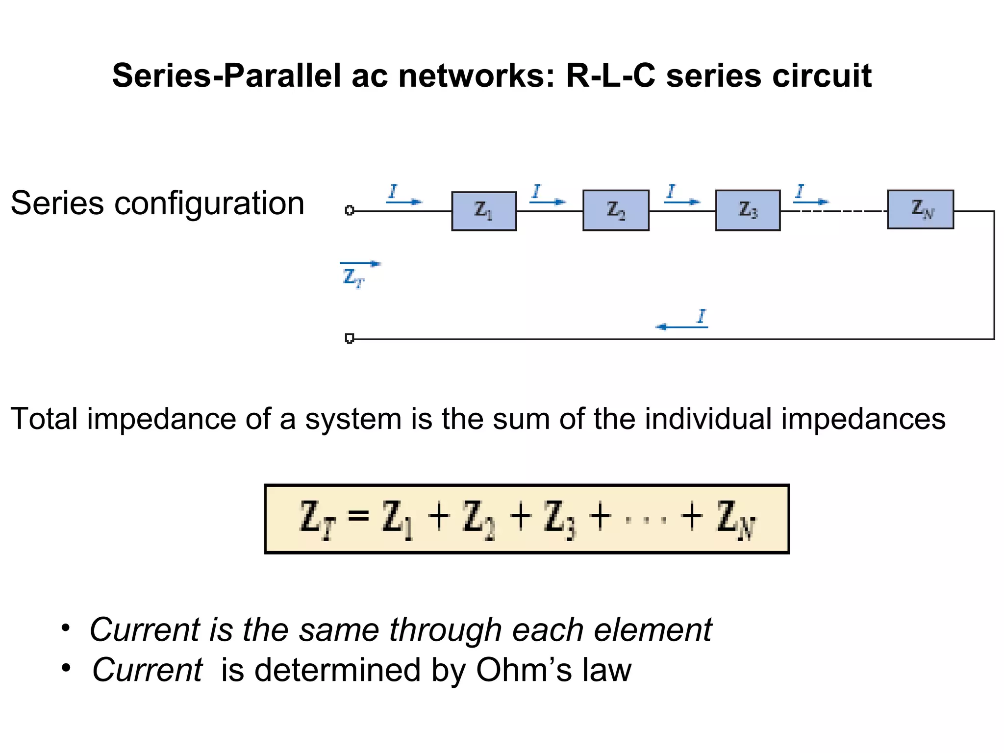
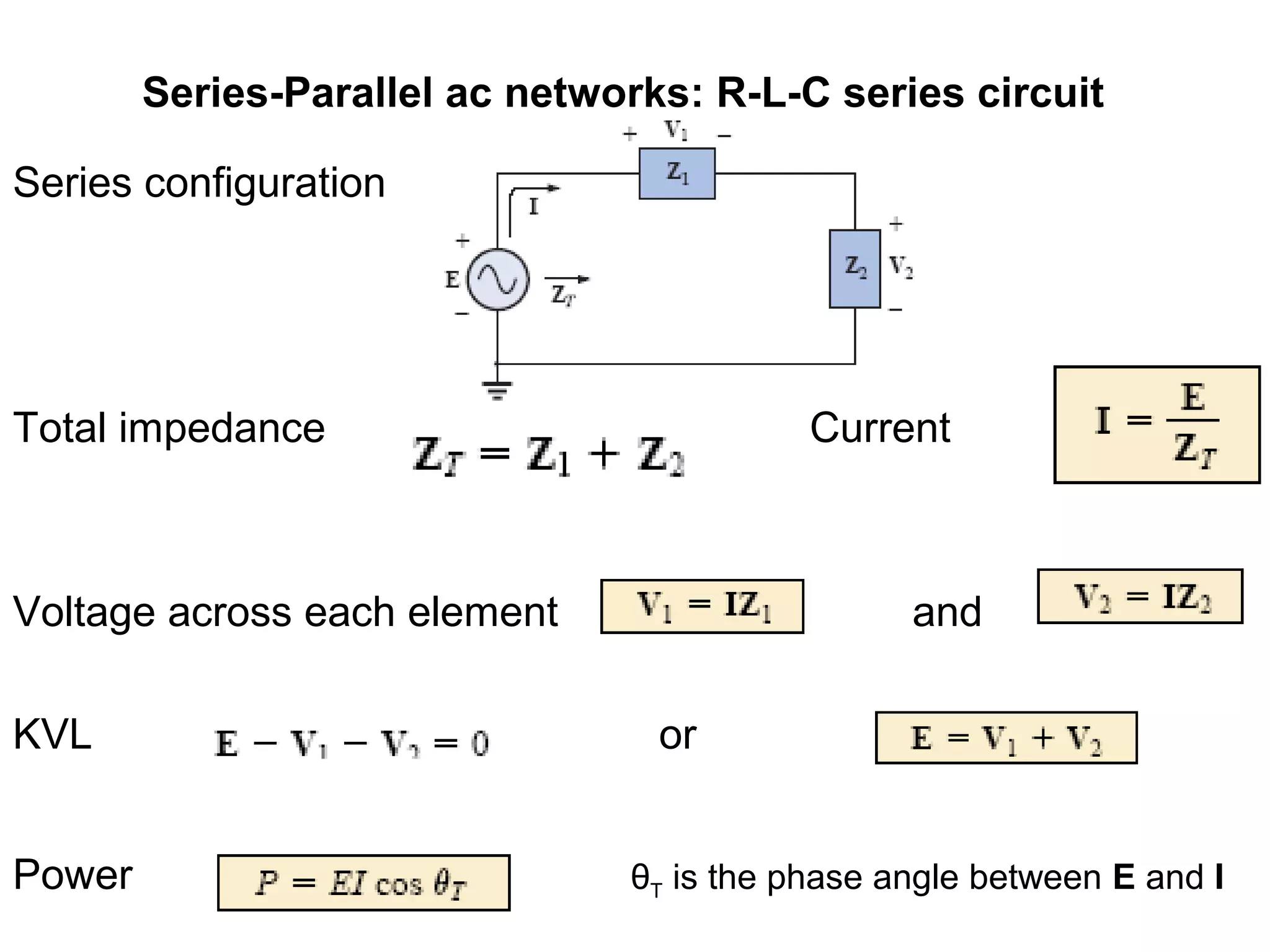
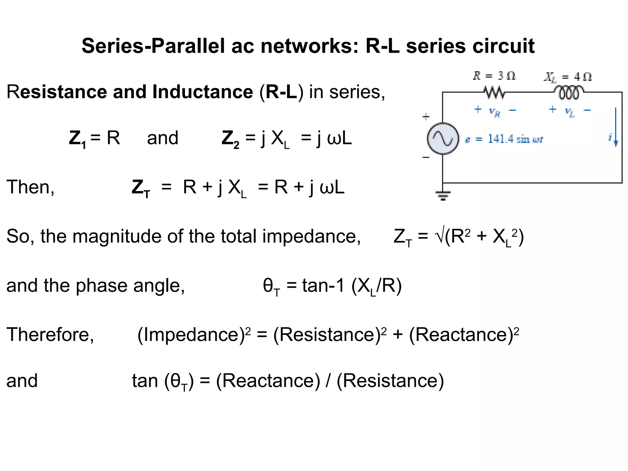
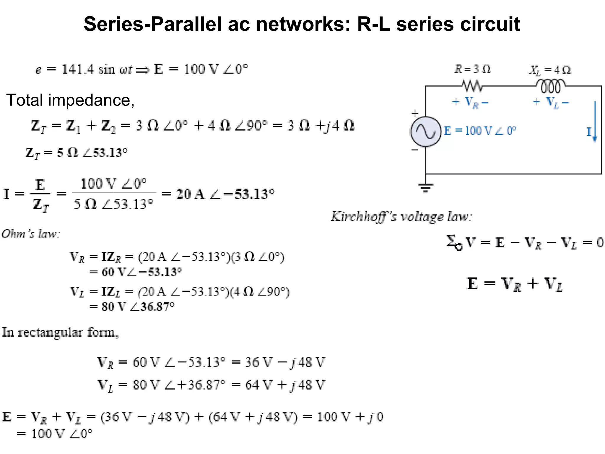
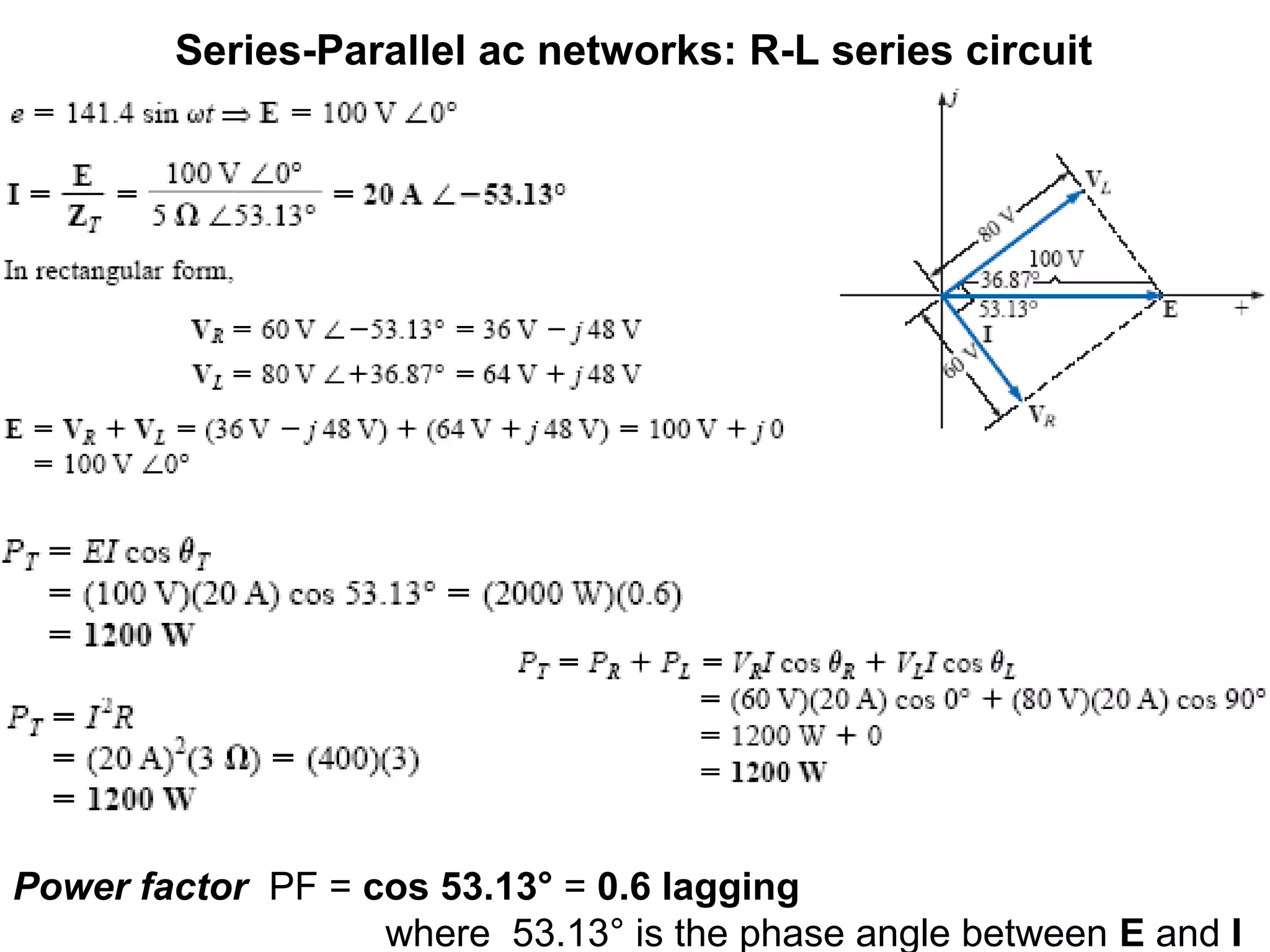
Series resistance, inductance and capacitance (R-L-C) circuit,
Z1 = R, Z2 = j XL = j ωL and Z3 = 1/(jXC)
= -j/ωC
Then, ZT = R + j XL - j XC = R + j ωL - j /ωC
= R + j (XL - XC) = R + j (ωL - 1/ωC)
So, the magnitude of the total impedance, ZT = √(R2
+ (XL -
XC)2
and the phase angle, θT = tan-1 [(XL – XC)/R]
Therefore, (Impedance)2
= (Resistance)2
+ (Total Reactance)2](https://image.slidesharecdn.com/series-parallelacrlcnetworks-161201204003/75/Series-parallel-ac-rlc-networks-6-2048.jpg)

The document explains series-parallel AC networks focusing on R-L-C series circuits, detailing how current and impedance are calculated according to Ohm's law. It outlines the formulas for total impedance and phase angles for R-L, R-C, and R-L-C configurations. Additionally, it provides examples for determining input impedance and calculating power factor.