SlideShare a Scribd company logo
RLC Series and Parallel Circuit
Department of Electrical Engineering
BY:- Shah Krishnaji
Patel Daxil
Patel Dakshit
Patil Parita S.
Panchal Swapnil
Guided by:-Prof. (Dr.) A. R. Chudasama
Mrs. Nidhi Gohil
Neotech Institute of Technology 1
OBJECTIVES
• Become familiar with the characteristics of series and
parallel ac networks and be able to find current, voltage, and
power for each element.
• Be able to find the total impedance of any series or parallel
ac network and sketch the impedance and admittance
diagram of each.
• Applying KVL and KCL to any series or parallel configuration.
• Be able to apply the VDR or CDR to any ac network.
Neotech Institute of Technology 2
IMPEDANCE AND THE PHASOR DIAGRAM
Resistive Elements
•For purely resistive circuit v and i were in phase,
and the magnitude:
FIG. 15.1 Resistive ac circuit.
• In phasor form,
Neotech Institute of Technology 3
IMPEDANCE AND THE PHASOR DIAGRAM
Resistive Elements
FIG. 15.4 Example
15.2.
FIG. 15.5 Waveforms for Example 15.2.
Neotech Institute of Technology 4
IMPEDANCE AND THE PHASOR DIAGRAM
Inductive Reactance
FIG. 15.8 Example
15.3.
FIG. 15.9 Waveforms for Example
15.3.
• for the pure inductor, the voltage leads the
current by 90° and that the reactance of the
coil XL is determined by ψL.
Neotech Institute of Technology 5
IMPEDANCE AND THE PHASOR DIAGRAM
Inductive Reactance
FIG. 15.12 Phasor diagrams for Examples 15.3 and 15.4.
Neotech Institute of Technology 6
IMPEDANCE AND THE PHASOR DIAGRAM
Capacitive Reactance
FIG. 15.16 Example
15.6.
FIG. 15.17 Waveforms for Example
15.6.
• for the pure capacitor, the current leads the
voltage by 90° and that the reactance of the
capacitor XC is determined by 1/ψC.
Neotech Institute of Technology 7
IMPEDANCE AND THE PHASOR DIAGRAM
Capacitive Reactance
FIG. 15.18 Phasor diagrams for
Examples 15.5 and 15.6.
Neotech Institute of Technology 8
IMPEDANCE AND THE PHASOR DIAGRAM
Impedance Diagram
•Now that an angle is
associated with resistance
R, inductive reactance XL,
and capacitive reactance
XC, each can be placed on
a complex plane diagram.
FIG. 15.19 Impedance diagram.
Neotech Institute of Technology 9
SERIES CONFIGURATION
FIG. 15.20 Series impedances.
Neotech Institute of Technology 10
VOLTAGE DIVIDER RULE
FIG. 15.41 Example 15.10.
Neotech Institute of Technology 11
FREQUENCY RESPONSE FOR SERIES ac
CIRCUITS
FIG. 15.46 Reviewing the frequency response of the basic elements.
Neotech Institute of Technology 12
ADMITTANCE AND SUSCEPTANCE
• In ac circuits, we define admittance (Y) as being equal to
1/Z.
• The unit of measure for admittance as defined by the SI
system is siemens, which has the symbol S.
• Admittance is a measure of how well an ac circuit will admit,
or allow, current to flow in the circuit.
• The larger its value, therefore, the heavier is the current flow
for the same applied potential.
• The total admittance of a circuit can also be found by finding
the sum of the parallel admittances.
Neotech Institute of Technology 13
ADMITTANCE AND SUSCEPTANCE
FIG. 15.58 Parallel ac network.
Neotech Institute of Technology 14
ADMITTANCE AND SUSCEPTANCE
FIG. 15.59 Admittance diagram.
Neotech Institute of Technology 15
ADMITTANCE AND SUSCEPTANCE
FIG. 15.64 Impedance diagram for the
network in Fig. 15.63.
FIG. 15.65 Admittance diagram for the
network in Fig. 15.63.
FIG. 15.63 Example 15.14.
Neotech Institute of Technology 16
PARALLEL ac NETWORKS
FIG. 15.67 Parallel ac network.
Neotech Institute of Technology 17
PARALLEL ac NETWORKS
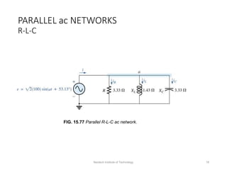
R-L-C
FIG. 15.77 Parallel R-L-C ac network.
Neotech Institute of Technology 18
PARALLEL ac NETWORKS
R-L-C
FIG. 15.78 Applying phasor notation to the network in Fig. 15.77.
Neotech Institute of Technology 19
PARALLEL ac NETWORKS
R-L-C
FIG. 15.79 Admittance diagram for the
parallel R-L-C network in Fig. 15.77.
FIG. 15.80 Phasor diagram for the
parallel R-L-C network in Fig. 15.77.
Neotech Institute of Technology 20
PARALLEL ac NETWORKS
R-L-C
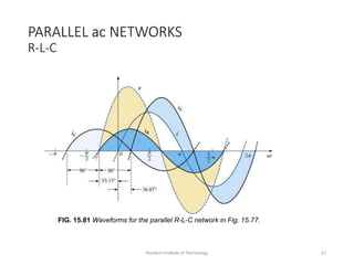
FIG. 15.81 Waveforms for the parallel R-L-C network in Fig. 15.77.
Neotech Institute of Technology 21
CURRENT DIVIDER RULE
FIG. 15.83 Example 15.16. FIG. 15.84 Example 15.17.
FIG. 15.82 Applying the current divider rule.
Neotech Institute of Technology 22
Thank you
Neotech Institute of Technology 23

More Related Content

Similar to RLC Series and parallel.ppt

EE6511-CONTROL-AND-INSTRUMENTATION-LABORATORY.doc
EE6511-CONTROL-AND-INSTRUMENTATION-LABORATORY.docEE6511-CONTROL-AND-INSTRUMENTATION-LABORATORY.doc
EE6511-CONTROL-AND-INSTRUMENTATION-LABORATORY.doc
Arul Prakash
 
ENEL301 report _Joseph Haystead_1132999
ENEL301 report _Joseph Haystead_1132999ENEL301 report _Joseph Haystead_1132999
ENEL301 report _Joseph Haystead_1132999
Joseph Haystead
 
Unit-02 Basic of AC Circuits.pptx
Unit-02 Basic of AC Circuits.pptxUnit-02 Basic of AC Circuits.pptx
Unit-02 Basic of AC Circuits.pptx
Rajneesh501415
 
Loren k. schwappach ee331 - lab 3
Loren k. schwappach   ee331 - lab 3Loren k. schwappach   ee331 - lab 3
Loren k. schwappach ee331 - lab 3
Loren Schwappach
 

Similar to RLC Series and parallel.ppt (20)

236793460 ee6361-electric-circuit-lab-docx
236793460 ee6361-electric-circuit-lab-docx236793460 ee6361-electric-circuit-lab-docx
236793460 ee6361-electric-circuit-lab-docx
 
An Approach to Voltage Quality Enhancement by Introduction of CWVM for Distri...
An Approach to Voltage Quality Enhancement by Introduction of CWVM for Distri...An Approach to Voltage Quality Enhancement by Introduction of CWVM for Distri...
An Approach to Voltage Quality Enhancement by Introduction of CWVM for Distri...
 
E&e lab manual
E&e lab manualE&e lab manual
E&e lab manual
 
2nd year iv sem emi lab manual
2nd year iv sem emi lab manual2nd year iv sem emi lab manual
2nd year iv sem emi lab manual
 
EE6511-CONTROL-AND-INSTRUMENTATION-LABORATORY.doc
EE6511-CONTROL-AND-INSTRUMENTATION-LABORATORY.docEE6511-CONTROL-AND-INSTRUMENTATION-LABORATORY.doc
EE6511-CONTROL-AND-INSTRUMENTATION-LABORATORY.doc
 
Modeling of solar array and analyze the current transient
Modeling of solar array and analyze the current transientModeling of solar array and analyze the current transient
Modeling of solar array and analyze the current transient
 
Modeling of solar array and analyze the current transient response of shunt s...
Modeling of solar array and analyze the current transient response of shunt s...Modeling of solar array and analyze the current transient response of shunt s...
Modeling of solar array and analyze the current transient response of shunt s...
 
ENHANCEMENT OF ACTIVE POWER FLOW CAPACITY OF A TRANSMISSION LINE USING MSC‐TC...
ENHANCEMENT OF ACTIVE POWER FLOW CAPACITY OF A TRANSMISSION LINE USING MSC‐TC...ENHANCEMENT OF ACTIVE POWER FLOW CAPACITY OF A TRANSMISSION LINE USING MSC‐TC...
ENHANCEMENT OF ACTIVE POWER FLOW CAPACITY OF A TRANSMISSION LINE USING MSC‐TC...
 
Experiment 3.pptx
Experiment 3.pptxExperiment 3.pptx
Experiment 3.pptx
 
Eca on nortons and thevenins theoren and matlab simulation
Eca on nortons and thevenins theoren and matlab simulationEca on nortons and thevenins theoren and matlab simulation
Eca on nortons and thevenins theoren and matlab simulation
 
ENEL301 report _Joseph Haystead_1132999
ENEL301 report _Joseph Haystead_1132999ENEL301 report _Joseph Haystead_1132999
ENEL301 report _Joseph Haystead_1132999
 
PERFORMANCE ANALYSIS OF MODIFIED QSERL CIRCUIT
PERFORMANCE ANALYSIS OF MODIFIED QSERL CIRCUITPERFORMANCE ANALYSIS OF MODIFIED QSERL CIRCUIT
PERFORMANCE ANALYSIS OF MODIFIED QSERL CIRCUIT
 
Unit-02 Basic of AC Circuits.pptx
Unit-02 Basic of AC Circuits.pptxUnit-02 Basic of AC Circuits.pptx
Unit-02 Basic of AC Circuits.pptx
 
Design of 5.1 GHz ultra-low power and wide tuning range hybrid oscillator
Design of 5.1 GHz ultra-low power and wide tuning range  hybrid oscillatorDesign of 5.1 GHz ultra-low power and wide tuning range  hybrid oscillator
Design of 5.1 GHz ultra-low power and wide tuning range hybrid oscillator
 
Ch-2 AC.pdf
Ch-2 AC.pdfCh-2 AC.pdf
Ch-2 AC.pdf
 
Modeling and Simulation of Three Phase D-SVC for Load Compensation
Modeling and Simulation of Three Phase D-SVC for Load CompensationModeling and Simulation of Three Phase D-SVC for Load Compensation
Modeling and Simulation of Three Phase D-SVC for Load Compensation
 
Loren k. schwappach ee331 - lab 3
Loren k. schwappach   ee331 - lab 3Loren k. schwappach   ee331 - lab 3
Loren k. schwappach ee331 - lab 3
 
Hv3613741380
Hv3613741380Hv3613741380
Hv3613741380
 
Hv3613741380
Hv3613741380Hv3613741380
Hv3613741380
 
H06 elo e
H06 elo eH06 elo e
H06 elo e
 

Recently uploaded

Industrial Training Report- AKTU Industrial Training Report
Industrial Training Report- AKTU Industrial Training ReportIndustrial Training Report- AKTU Industrial Training Report
Industrial Training Report- AKTU Industrial Training Report
Avinash Rai
 
The Roman Empire A Historical Colossus.pdf
The Roman Empire A Historical Colossus.pdfThe Roman Empire A Historical Colossus.pdf
The Roman Empire A Historical Colossus.pdf
kaushalkr1407
 

Recently uploaded (20)

Phrasal Verbs.XXXXXXXXXXXXXXXXXXXXXXXXXX
Phrasal Verbs.XXXXXXXXXXXXXXXXXXXXXXXXXXPhrasal Verbs.XXXXXXXXXXXXXXXXXXXXXXXXXX
Phrasal Verbs.XXXXXXXXXXXXXXXXXXXXXXXXXX
 
Danh sách HSG Bộ môn cấp trường - Cấp THPT.pdf
Danh sách HSG Bộ môn cấp trường - Cấp THPT.pdfDanh sách HSG Bộ môn cấp trường - Cấp THPT.pdf
Danh sách HSG Bộ môn cấp trường - Cấp THPT.pdf
 
Basic Civil Engineering Notes of Chapter-6, Topic- Ecosystem, Biodiversity G...
Basic Civil Engineering Notes of Chapter-6,  Topic- Ecosystem, Biodiversity G...Basic Civil Engineering Notes of Chapter-6,  Topic- Ecosystem, Biodiversity G...
Basic Civil Engineering Notes of Chapter-6, Topic- Ecosystem, Biodiversity G...
 
PART A. Introduction to Costumer Service
PART A. Introduction to Costumer ServicePART A. Introduction to Costumer Service
PART A. Introduction to Costumer Service
 
Fish and Chips - have they had their chips
Fish and Chips - have they had their chipsFish and Chips - have they had their chips
Fish and Chips - have they had their chips
 
Palestine last event orientationfvgnh .pptx
Palestine last event orientationfvgnh .pptxPalestine last event orientationfvgnh .pptx
Palestine last event orientationfvgnh .pptx
 
How to Break the cycle of negative Thoughts
How to Break the cycle of negative ThoughtsHow to Break the cycle of negative Thoughts
How to Break the cycle of negative Thoughts
 
1.4 modern child centered education - mahatma gandhi-2.pptx
1.4 modern child centered education - mahatma gandhi-2.pptx1.4 modern child centered education - mahatma gandhi-2.pptx
1.4 modern child centered education - mahatma gandhi-2.pptx
 
Benefits and Challenges of Using Open Educational Resources
Benefits and Challenges of Using Open Educational ResourcesBenefits and Challenges of Using Open Educational Resources
Benefits and Challenges of Using Open Educational Resources
 
B.ed spl. HI pdusu exam paper-2023-24.pdf
B.ed spl. HI pdusu exam paper-2023-24.pdfB.ed spl. HI pdusu exam paper-2023-24.pdf
B.ed spl. HI pdusu exam paper-2023-24.pdf
 
Home assignment II on Spectroscopy 2024 Answers.pdf
Home assignment II on Spectroscopy 2024 Answers.pdfHome assignment II on Spectroscopy 2024 Answers.pdf
Home assignment II on Spectroscopy 2024 Answers.pdf
 
How to Create Map Views in the Odoo 17 ERP
How to Create Map Views in the Odoo 17 ERPHow to Create Map Views in the Odoo 17 ERP
How to Create Map Views in the Odoo 17 ERP
 
INU_CAPSTONEDESIGN_비밀번호486_업로드용 발표자료.pdf
INU_CAPSTONEDESIGN_비밀번호486_업로드용 발표자료.pdfINU_CAPSTONEDESIGN_비밀번호486_업로드용 발표자료.pdf
INU_CAPSTONEDESIGN_비밀번호486_업로드용 발표자료.pdf
 
GIÁO ÁN DẠY THÊM (KẾ HOẠCH BÀI BUỔI 2) - TIẾNG ANH 8 GLOBAL SUCCESS (2 CỘT) N...
GIÁO ÁN DẠY THÊM (KẾ HOẠCH BÀI BUỔI 2) - TIẾNG ANH 8 GLOBAL SUCCESS (2 CỘT) N...GIÁO ÁN DẠY THÊM (KẾ HOẠCH BÀI BUỔI 2) - TIẾNG ANH 8 GLOBAL SUCCESS (2 CỘT) N...
GIÁO ÁN DẠY THÊM (KẾ HOẠCH BÀI BUỔI 2) - TIẾNG ANH 8 GLOBAL SUCCESS (2 CỘT) N...
 
Industrial Training Report- AKTU Industrial Training Report
Industrial Training Report- AKTU Industrial Training ReportIndustrial Training Report- AKTU Industrial Training Report
Industrial Training Report- AKTU Industrial Training Report
 
Supporting (UKRI) OA monographs at Salford.pptx
Supporting (UKRI) OA monographs at Salford.pptxSupporting (UKRI) OA monographs at Salford.pptx
Supporting (UKRI) OA monographs at Salford.pptx
 
Basic phrases for greeting and assisting costumers
Basic phrases for greeting and assisting costumersBasic phrases for greeting and assisting costumers
Basic phrases for greeting and assisting costumers
 
The Roman Empire A Historical Colossus.pdf
The Roman Empire A Historical Colossus.pdfThe Roman Empire A Historical Colossus.pdf
The Roman Empire A Historical Colossus.pdf
 
The Art Pastor's Guide to Sabbath | Steve Thomason
The Art Pastor's Guide to Sabbath | Steve ThomasonThe Art Pastor's Guide to Sabbath | Steve Thomason
The Art Pastor's Guide to Sabbath | Steve Thomason
 
Embracing GenAI - A Strategic Imperative
Embracing GenAI - A Strategic ImperativeEmbracing GenAI - A Strategic Imperative
Embracing GenAI - A Strategic Imperative
 

RLC Series and parallel.ppt

  • 1. RLC Series and Parallel Circuit Department of Electrical Engineering BY:- Shah Krishnaji Patel Daxil Patel Dakshit Patil Parita S. Panchal Swapnil Guided by:-Prof. (Dr.) A. R. Chudasama Mrs. Nidhi Gohil Neotech Institute of Technology 1
  • 2. OBJECTIVES • Become familiar with the characteristics of series and parallel ac networks and be able to find current, voltage, and power for each element. • Be able to find the total impedance of any series or parallel ac network and sketch the impedance and admittance diagram of each. • Applying KVL and KCL to any series or parallel configuration. • Be able to apply the VDR or CDR to any ac network. Neotech Institute of Technology 2
  • 3. IMPEDANCE AND THE PHASOR DIAGRAM Resistive Elements •For purely resistive circuit v and i were in phase, and the magnitude: FIG. 15.1 Resistive ac circuit. • In phasor form, Neotech Institute of Technology 3
  • 4. IMPEDANCE AND THE PHASOR DIAGRAM Resistive Elements FIG. 15.4 Example 15.2. FIG. 15.5 Waveforms for Example 15.2. Neotech Institute of Technology 4
  • 5. IMPEDANCE AND THE PHASOR DIAGRAM Inductive Reactance FIG. 15.8 Example 15.3. FIG. 15.9 Waveforms for Example 15.3. • for the pure inductor, the voltage leads the current by 90° and that the reactance of the coil XL is determined by ψL. Neotech Institute of Technology 5
  • 6. IMPEDANCE AND THE PHASOR DIAGRAM Inductive Reactance FIG. 15.12 Phasor diagrams for Examples 15.3 and 15.4. Neotech Institute of Technology 6
  • 7. IMPEDANCE AND THE PHASOR DIAGRAM Capacitive Reactance FIG. 15.16 Example 15.6. FIG. 15.17 Waveforms for Example 15.6. • for the pure capacitor, the current leads the voltage by 90° and that the reactance of the capacitor XC is determined by 1/ψC. Neotech Institute of Technology 7
  • 8. IMPEDANCE AND THE PHASOR DIAGRAM Capacitive Reactance FIG. 15.18 Phasor diagrams for Examples 15.5 and 15.6. Neotech Institute of Technology 8
  • 9. IMPEDANCE AND THE PHASOR DIAGRAM Impedance Diagram •Now that an angle is associated with resistance R, inductive reactance XL, and capacitive reactance XC, each can be placed on a complex plane diagram. FIG. 15.19 Impedance diagram. Neotech Institute of Technology 9
  • 10. SERIES CONFIGURATION FIG. 15.20 Series impedances. Neotech Institute of Technology 10
  • 11. VOLTAGE DIVIDER RULE FIG. 15.41 Example 15.10. Neotech Institute of Technology 11
  • 12. FREQUENCY RESPONSE FOR SERIES ac CIRCUITS FIG. 15.46 Reviewing the frequency response of the basic elements. Neotech Institute of Technology 12
  • 13. ADMITTANCE AND SUSCEPTANCE • In ac circuits, we define admittance (Y) as being equal to 1/Z. • The unit of measure for admittance as defined by the SI system is siemens, which has the symbol S. • Admittance is a measure of how well an ac circuit will admit, or allow, current to flow in the circuit. • The larger its value, therefore, the heavier is the current flow for the same applied potential. • The total admittance of a circuit can also be found by finding the sum of the parallel admittances. Neotech Institute of Technology 13
  • 14. ADMITTANCE AND SUSCEPTANCE FIG. 15.58 Parallel ac network. Neotech Institute of Technology 14
  • 15. ADMITTANCE AND SUSCEPTANCE FIG. 15.59 Admittance diagram. Neotech Institute of Technology 15
  • 16. ADMITTANCE AND SUSCEPTANCE FIG. 15.64 Impedance diagram for the network in Fig. 15.63. FIG. 15.65 Admittance diagram for the network in Fig. 15.63. FIG. 15.63 Example 15.14. Neotech Institute of Technology 16
  • 17. PARALLEL ac NETWORKS FIG. 15.67 Parallel ac network. Neotech Institute of Technology 17
  • 18. PARALLEL ac NETWORKS R-L-C FIG. 15.77 Parallel R-L-C ac network. Neotech Institute of Technology 18
  • 19. PARALLEL ac NETWORKS R-L-C FIG. 15.78 Applying phasor notation to the network in Fig. 15.77. Neotech Institute of Technology 19
  • 20. PARALLEL ac NETWORKS R-L-C FIG. 15.79 Admittance diagram for the parallel R-L-C network in Fig. 15.77. FIG. 15.80 Phasor diagram for the parallel R-L-C network in Fig. 15.77. Neotech Institute of Technology 20
  • 21. PARALLEL ac NETWORKS R-L-C FIG. 15.81 Waveforms for the parallel R-L-C network in Fig. 15.77. Neotech Institute of Technology 21
  • 22. CURRENT DIVIDER RULE FIG. 15.83 Example 15.16. FIG. 15.84 Example 15.17. FIG. 15.82 Applying the current divider rule. Neotech Institute of Technology 22
  • 23. Thank you Neotech Institute of Technology 23