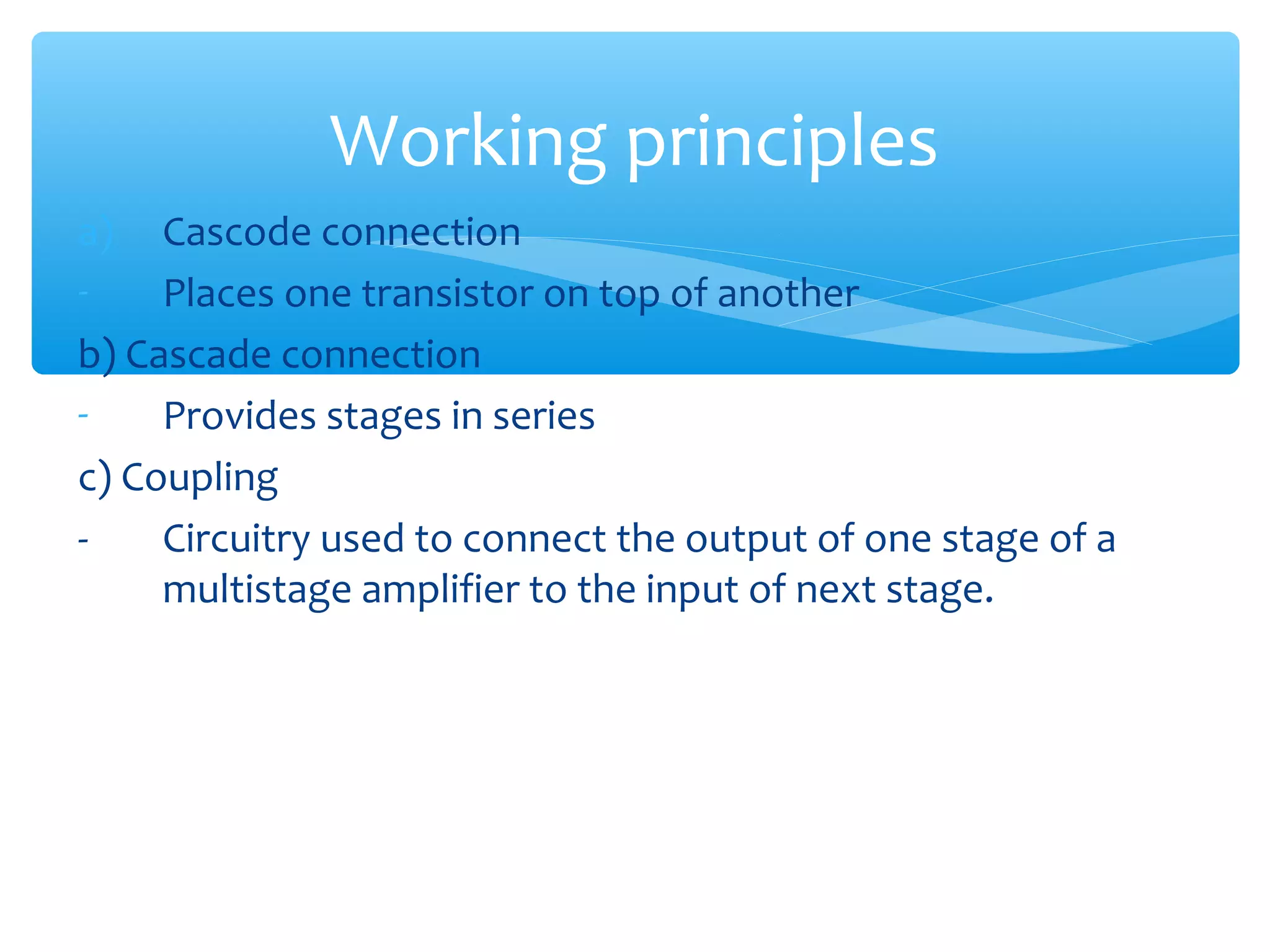
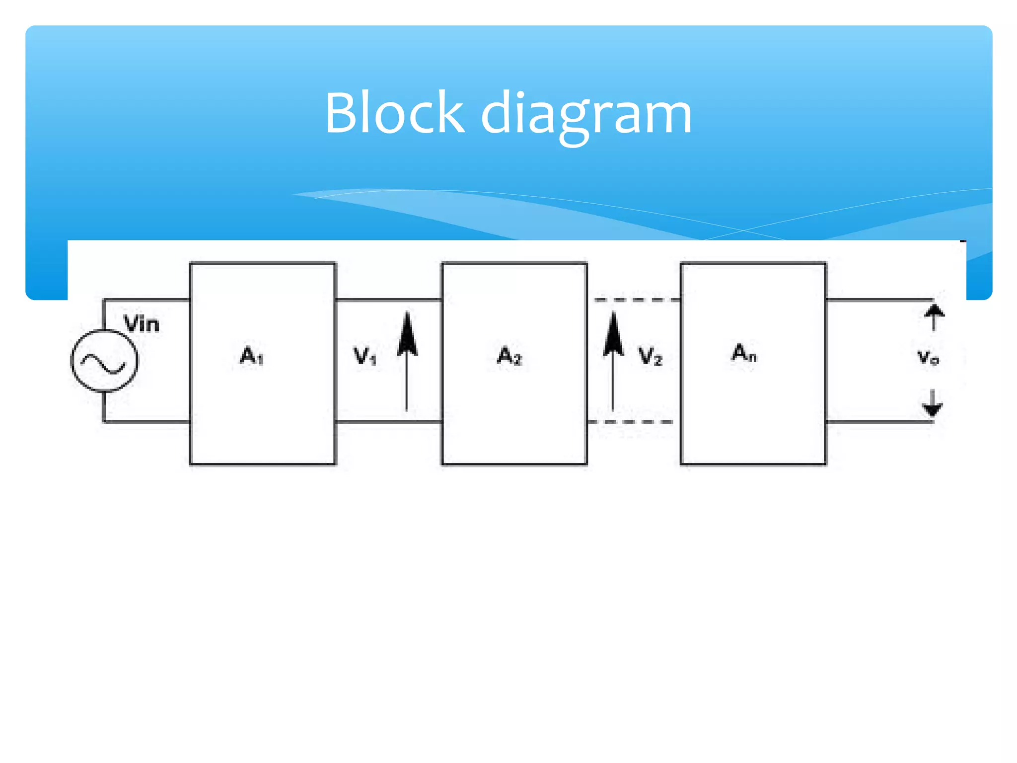
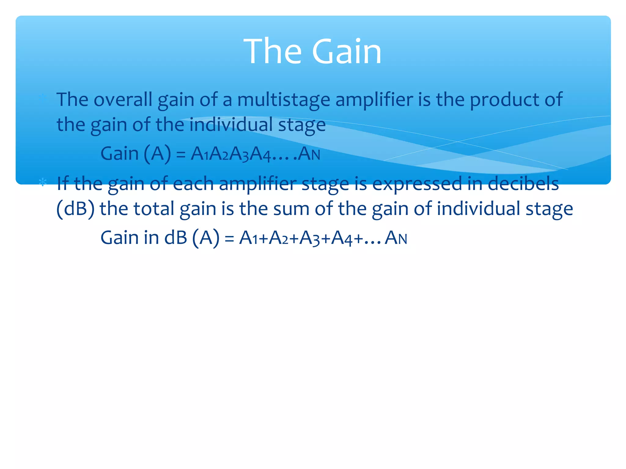
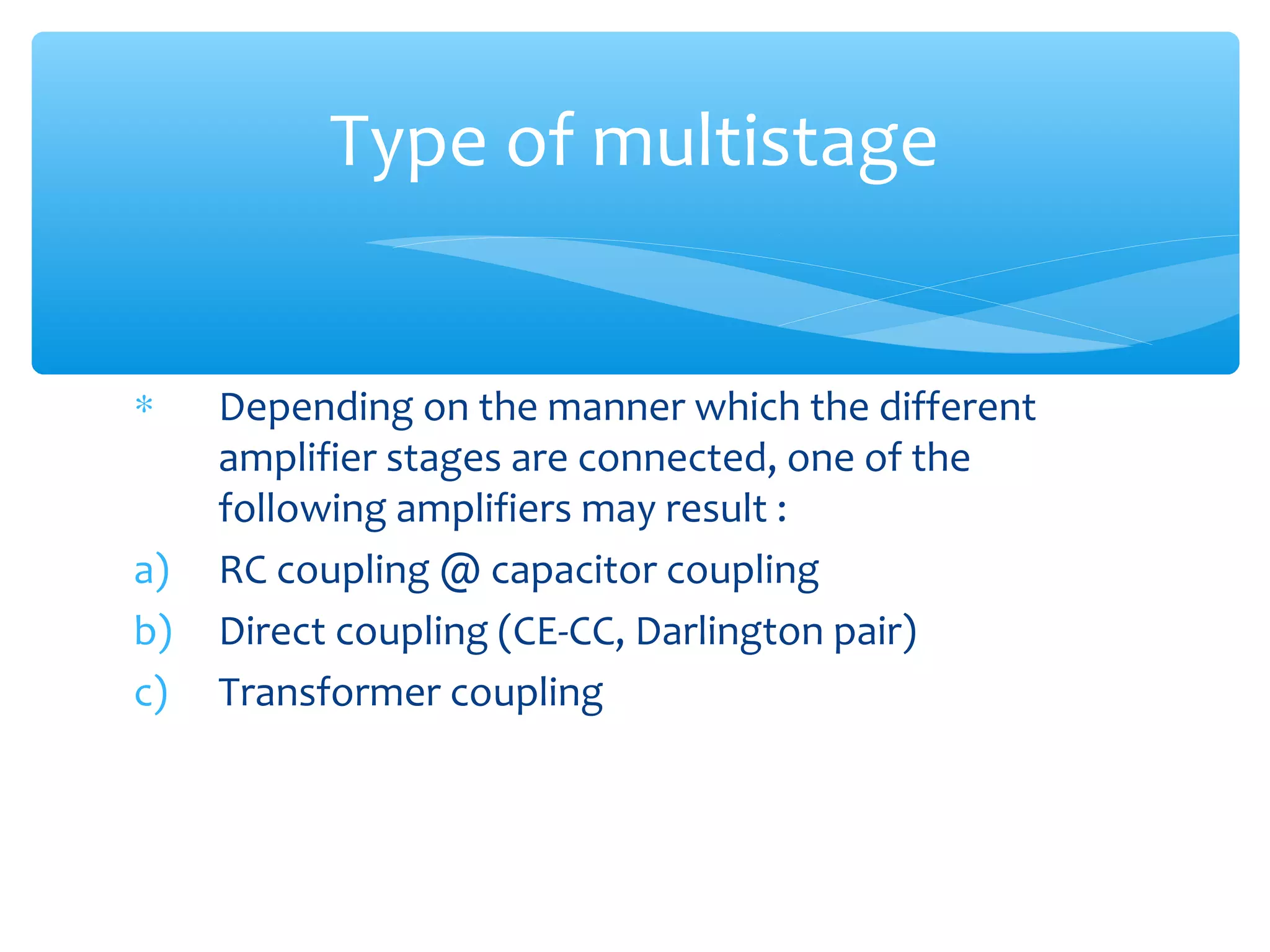
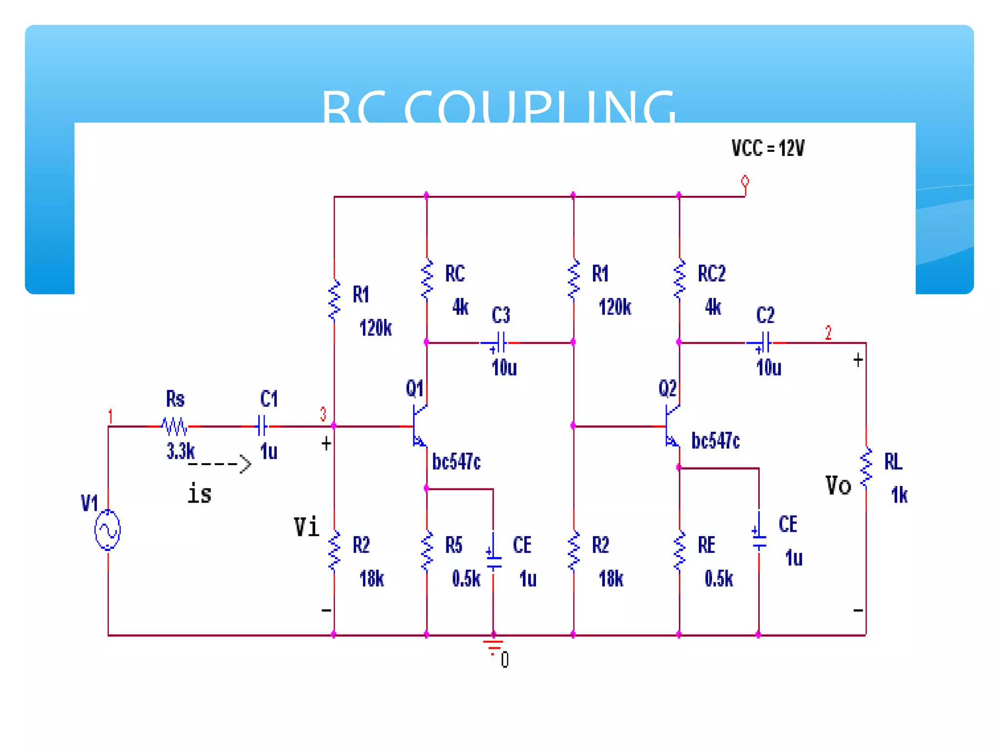
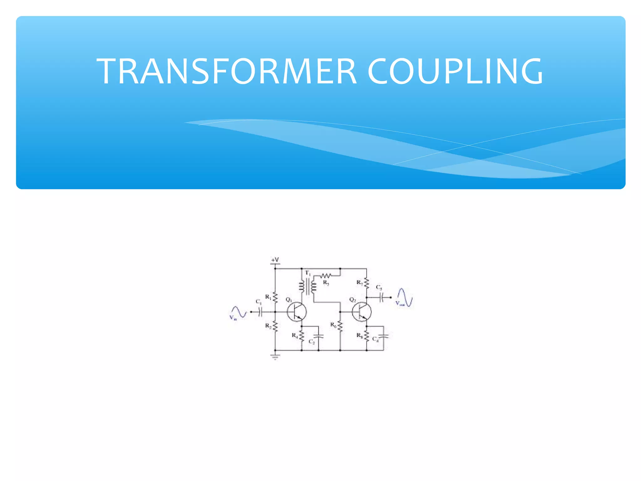
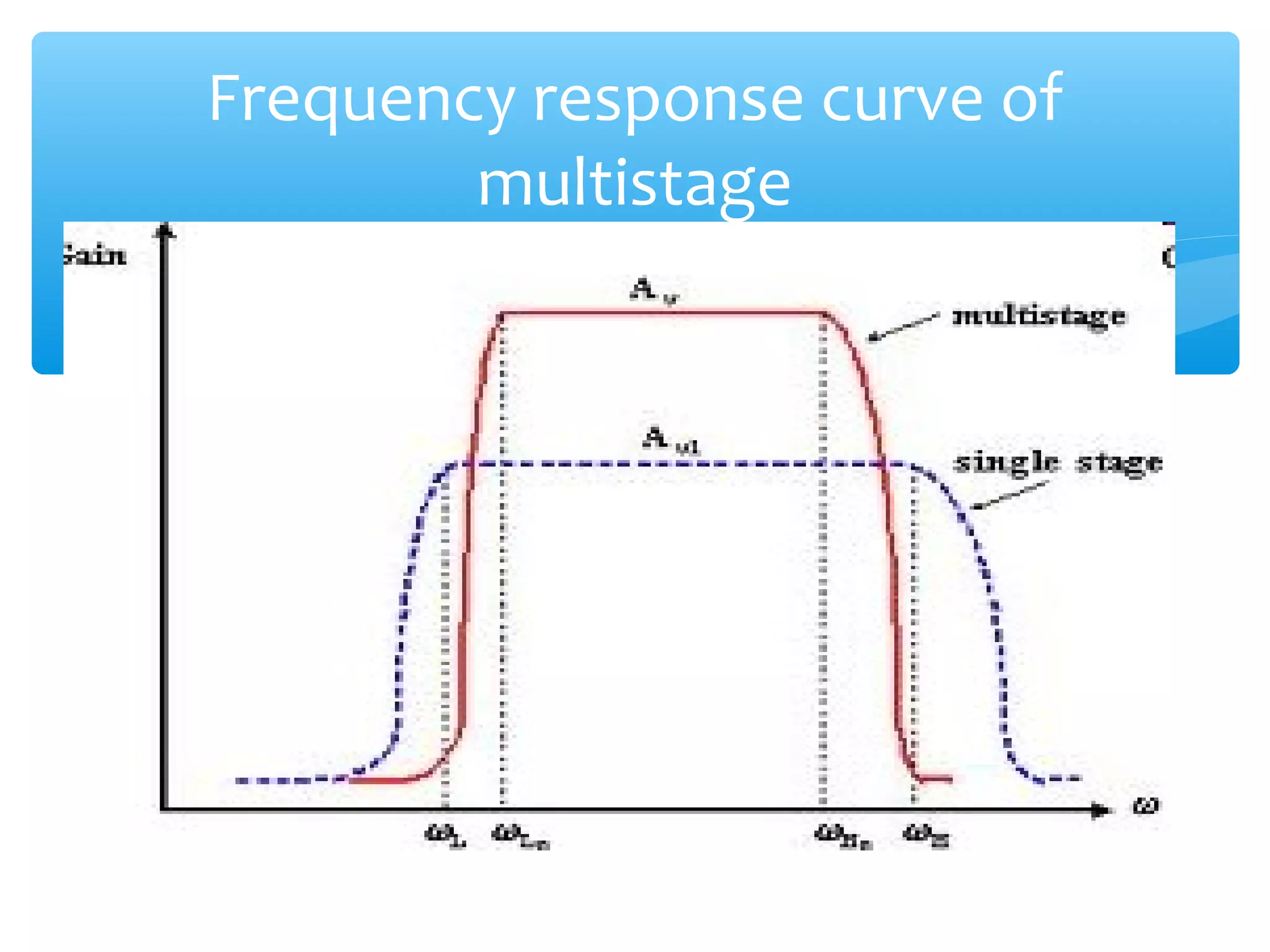
EE201-SEMICONDUCTOR
        DEVICES


CHAPTER 4 : MULTISTAGES
      AMPLIFIER
Introduction
∗ Amplifiers containing one active device have limited gain,
  input impedance, output impedance and power handling
  capabilities.
∗ Multistage amplifier is used to increase the gain or modify
  the characteristics of the amplifier to satisfy a particular
  specification.
Working principles
a)   Cascode connection
-    Places one transistor on top of another
b) Cascade connection
-    Provides stages in series
c) Coupling
-    Circuitry used to connect the output of one stage of a
     multistage amplifier to the input of next stage.
Block diagram
The Gain
∗ The overall gain of a multistage amplifier is the product of
  the gain of the individual stage
        Gain (A) = A1A2A3A4….AN
∗ If the gain of each amplifier stage is expressed in decibels
  (dB) the total gain is the sum of the gain of individual stage
        Gain in dB (A) = A1+A2+A3+A4+…AN
Type of multistage


∗    Depending on the manner which the different
     amplifier stages are connected, one of the
     following amplifiers may result :
a)   RC coupling @ capacitor coupling
b)   Direct coupling (CE-CC, Darlington pair)
c)   Transformer coupling
RC COUPLING
Cont’
∗ One way to connect various stage is via capacitor
∗ Coupling capacitor is used to block the flow of dc current
  between the output of one amplifier stage and the input of
  the next stage
Advantages


∗ Make dc bias at the output of one stage is different
  from dc bias voltage at the input to next stage
∗ Prevent the flow of dc signal current between stage
∗ Provides enough high frequency to keep capacitive
  reactance small
Disadvantage


∗ Affects the lower frequency response of amplifier
DIRECT COUPLING
Cont’
∗ In this type of amplifier, the output of one stage of amplifier
  is connected to the input of the next stage directly without
  using any reactive component like capacitor, inductor.
∗ As a result, the frequency response of this amplifier is quite
  flat all the way down to dc (0Hz)
Advantages


∗ Simple circuit
∗ Can be used to amplify zero and low frequency signal
∗ Used in differential and op-amp
Disadvantages


∗ At high frequency, gain decrease
∗ Transistor parameter change with temperature,
  hence output is affected by temperature variation
∗ Any noise appearing at the input also present at the
  output in amplified form due to high gain
DARLINGTON PAIR
Cont’
∗ Collector of two BJT are tied together and emitter of one is
  direct coupled to the base of the other
∗ The combination is used in amplifier circuit as if were a
  single transistor having three terminal – B,C,E
∗ Is important and useful configuration because has high B
                      BD = B1B2
TRANSFORMER COUPLING
Cont’


∗ Transformer coupling is where the primary winding is
  in the output of one stage and secondary winding is in
  the input circuit of the following stage
∗ The ac signal is passed from one stage to the next
  stage without the possibility of dc current flowing
  between the two windings
Advantages


∗ Low power dissipation
∗ Capability of designing a turn ratio that result in
  maximum power transfer between stage
∗ Often used in narrow band application (RF amplifier)
Disadvantages


∗ Poor frequency response due to inductance and inter-
  winding capacitance tend to reduce the usable
  bandwidth of these amplifier
Frequency response curve of
        multistage
Cont’


∗ The greater the number of identical stages, the lower
  cut-off frequency is increasing and the upper cut-off
  frequency is decreasing
∗ Therefore, this will reduce the bandwidth of the
  multistage amplifier

EE201 -Chapter 4

  • 1.
    EE201-SEMICONDUCTOR DEVICES CHAPTER 4 : MULTISTAGES AMPLIFIER
  • 2.
    Introduction ∗ Amplifiers containingone active device have limited gain, input impedance, output impedance and power handling capabilities. ∗ Multistage amplifier is used to increase the gain or modify the characteristics of the amplifier to satisfy a particular specification.
  • 3.
    Working principles a) Cascode connection - Places one transistor on top of another b) Cascade connection - Provides stages in series c) Coupling - Circuitry used to connect the output of one stage of a multistage amplifier to the input of next stage.
  • 4.
  • 5.
    The Gain ∗ Theoverall gain of a multistage amplifier is the product of the gain of the individual stage Gain (A) = A1A2A3A4….AN ∗ If the gain of each amplifier stage is expressed in decibels (dB) the total gain is the sum of the gain of individual stage Gain in dB (A) = A1+A2+A3+A4+…AN
  • 6.
    Type of multistage ∗ Depending on the manner which the different amplifier stages are connected, one of the following amplifiers may result : a) RC coupling @ capacitor coupling b) Direct coupling (CE-CC, Darlington pair) c) Transformer coupling
  • 7.
  • 8.
    Cont’ ∗ One wayto connect various stage is via capacitor ∗ Coupling capacitor is used to block the flow of dc current between the output of one amplifier stage and the input of the next stage
  • 9.
    Advantages ∗ Make dcbias at the output of one stage is different from dc bias voltage at the input to next stage ∗ Prevent the flow of dc signal current between stage ∗ Provides enough high frequency to keep capacitive reactance small
  • 10.
    Disadvantage ∗ Affects thelower frequency response of amplifier
  • 11.
  • 12.
    Cont’ ∗ In thistype of amplifier, the output of one stage of amplifier is connected to the input of the next stage directly without using any reactive component like capacitor, inductor. ∗ As a result, the frequency response of this amplifier is quite flat all the way down to dc (0Hz)
  • 13.
    Advantages ∗ Simple circuit ∗Can be used to amplify zero and low frequency signal ∗ Used in differential and op-amp
  • 14.
    Disadvantages ∗ At highfrequency, gain decrease ∗ Transistor parameter change with temperature, hence output is affected by temperature variation ∗ Any noise appearing at the input also present at the output in amplified form due to high gain
  • 15.
  • 16.
    Cont’ ∗ Collector oftwo BJT are tied together and emitter of one is direct coupled to the base of the other ∗ The combination is used in amplifier circuit as if were a single transistor having three terminal – B,C,E ∗ Is important and useful configuration because has high B BD = B1B2
  • 17.
  • 18.
    Cont’ ∗ Transformer couplingis where the primary winding is in the output of one stage and secondary winding is in the input circuit of the following stage ∗ The ac signal is passed from one stage to the next stage without the possibility of dc current flowing between the two windings
  • 19.
    Advantages ∗ Low powerdissipation ∗ Capability of designing a turn ratio that result in maximum power transfer between stage ∗ Often used in narrow band application (RF amplifier)
  • 20.
    Disadvantages ∗ Poor frequencyresponse due to inductance and inter- winding capacitance tend to reduce the usable bandwidth of these amplifier
  • 21.
  • 22.
    Cont’ ∗ The greaterthe number of identical stages, the lower cut-off frequency is increasing and the upper cut-off frequency is decreasing ∗ Therefore, this will reduce the bandwidth of the multistage amplifier