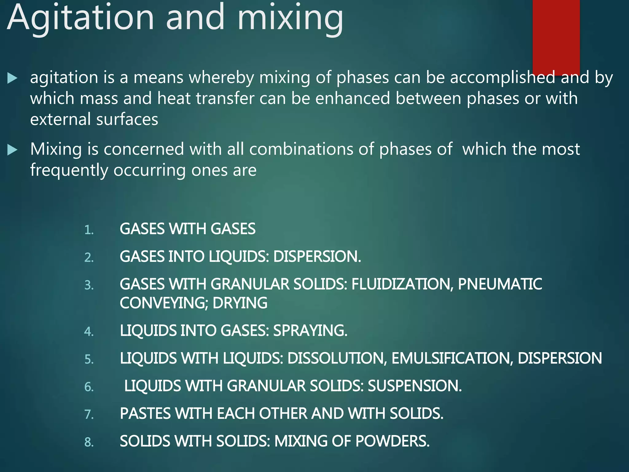
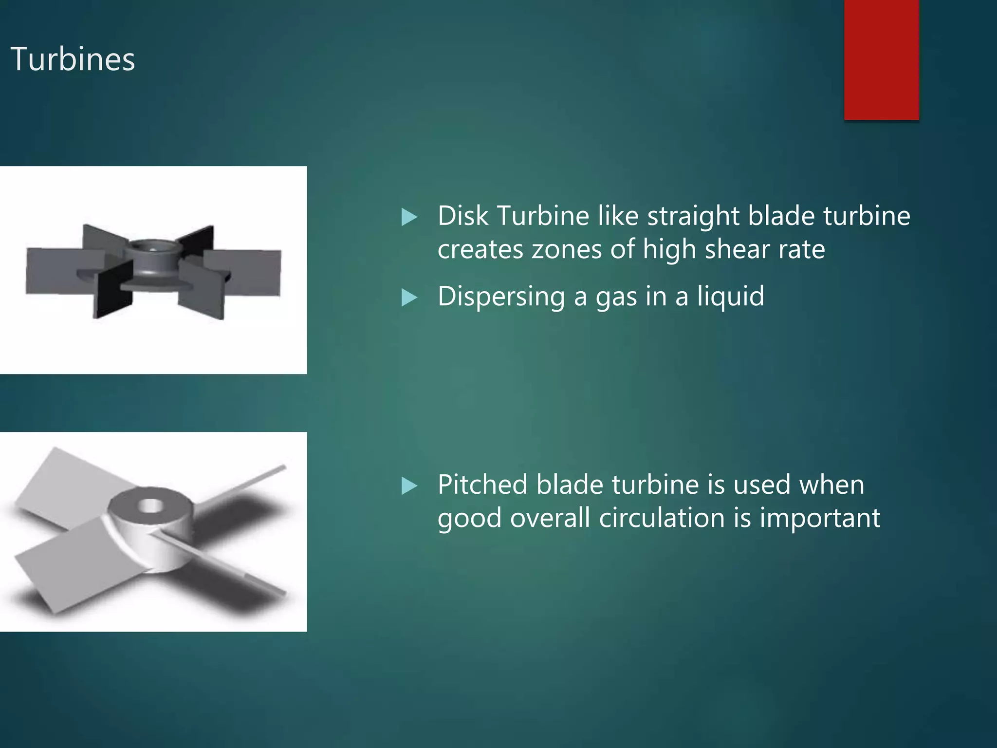
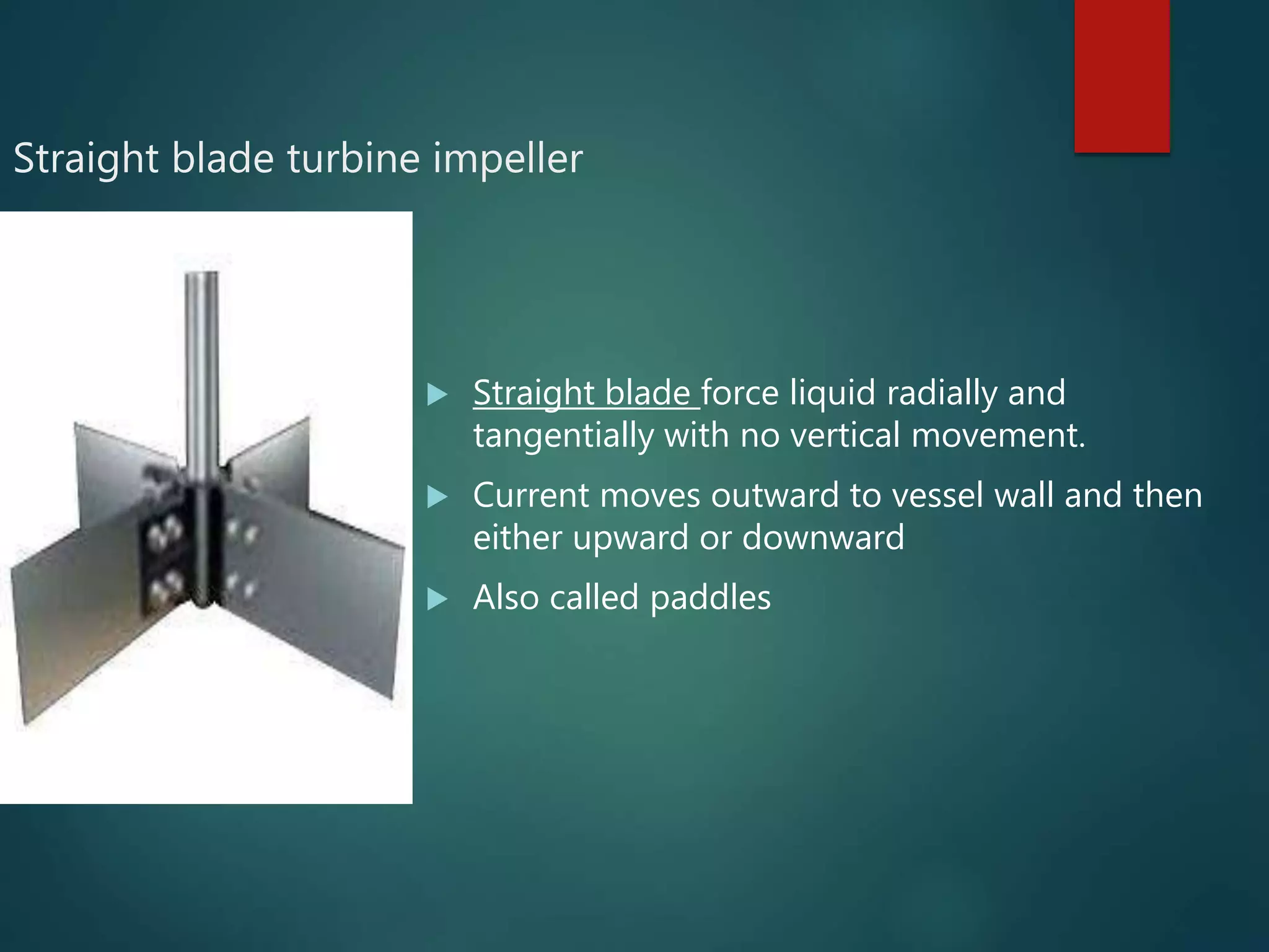
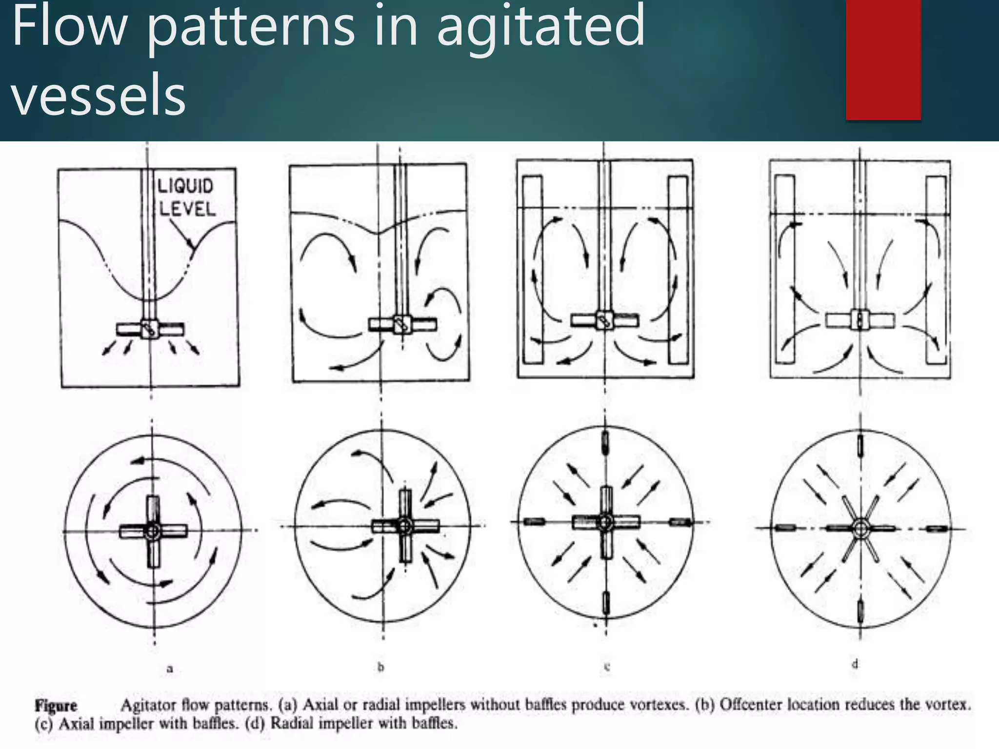
1. Agitation involves inducing motion within a material while mixing distributes components randomly.
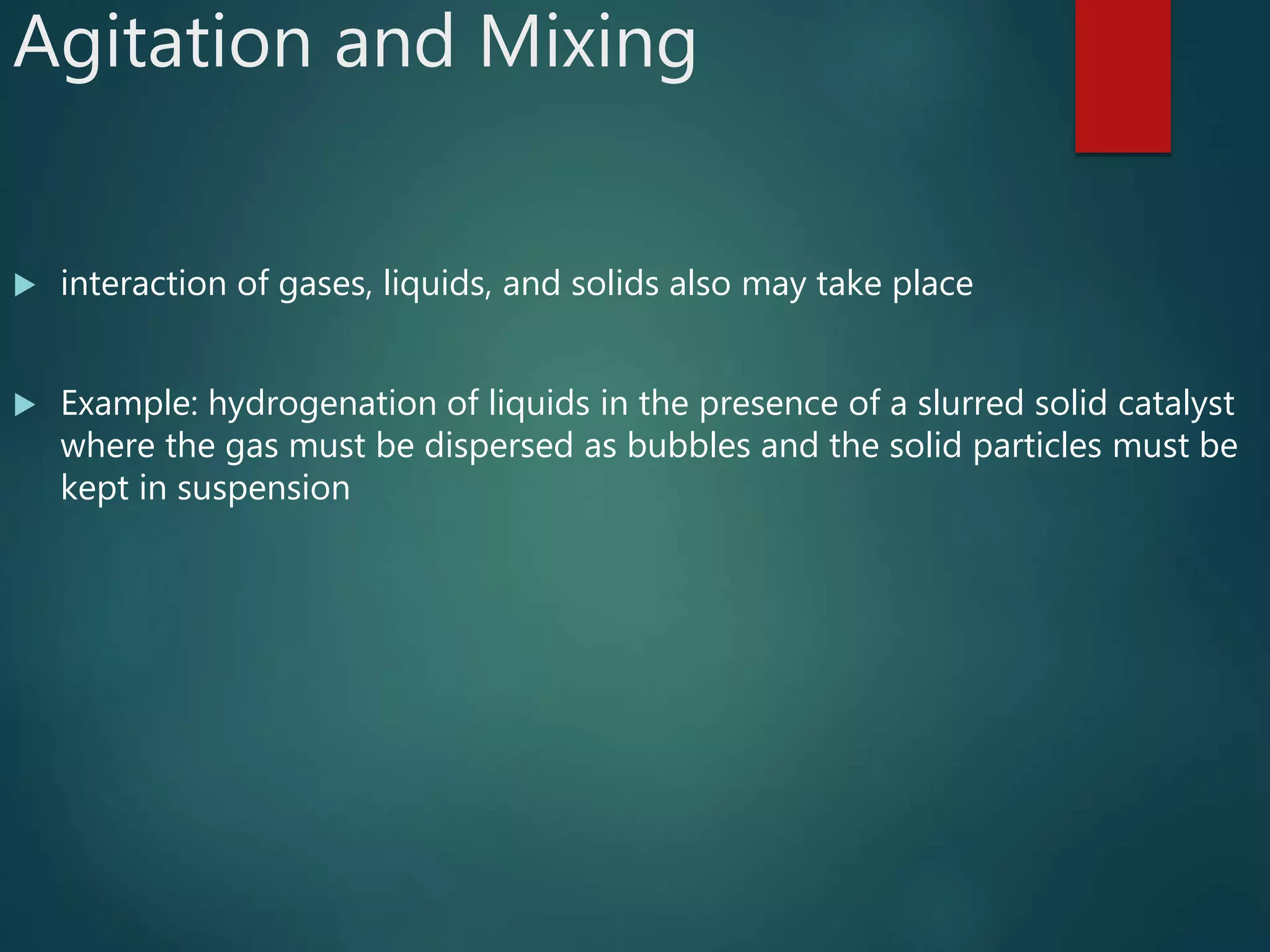
2. Mixing operations involve various combinations of gases, liquids, and solids and may require agitation to enhance mass and heat transfer between phases.
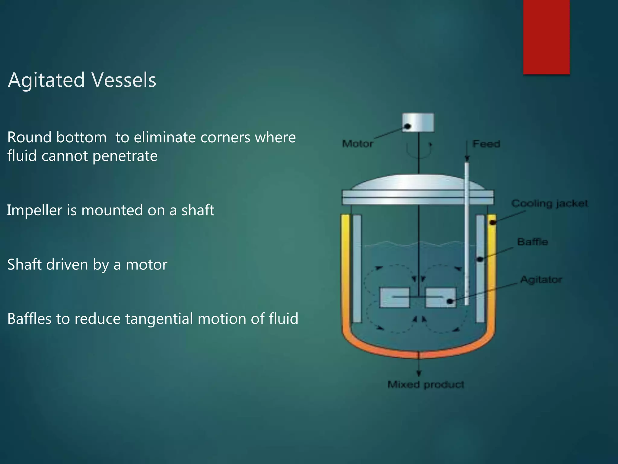
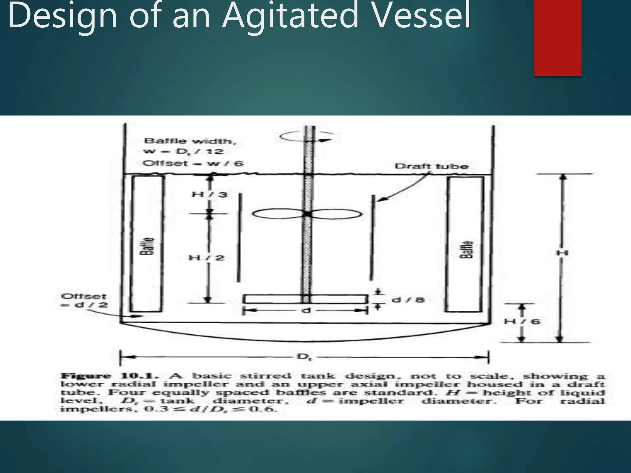
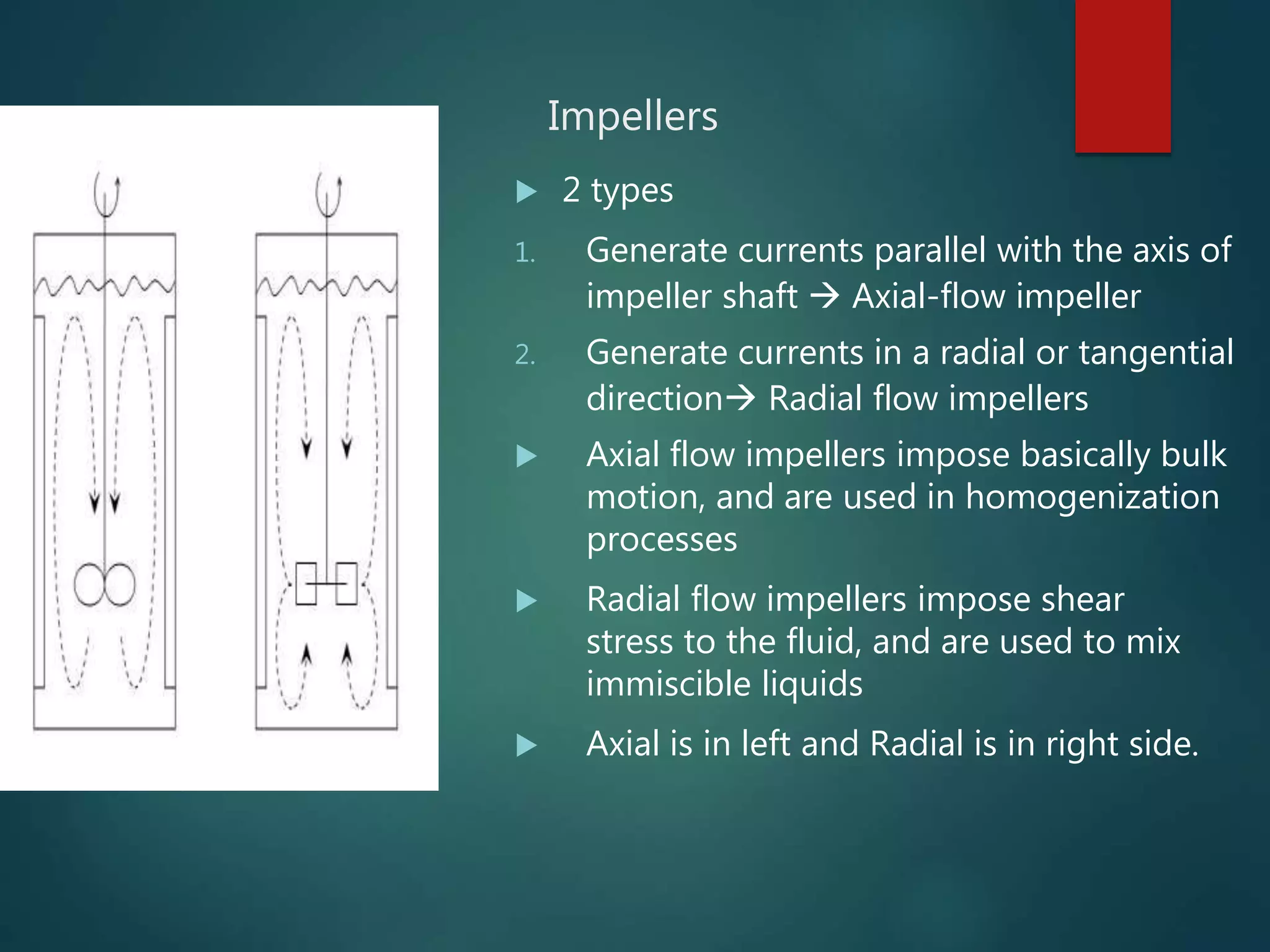
3. Effective agitation and mixing depends on factors like the impeller type, liquid properties, and vessel design which influence flow patterns within the vessel.


![[Paperwork] Mixing - Pharmaceutical Engineering](https://cdn.slidesharecdn.com/ss_thumbnails/papermixingcomplete-151107042824-lva1-app6892-thumbnail.jpg?width=640&height=640&fit=bounds)

![[Power Point] Mixing - Pharmaceutical Engineering](https://cdn.slidesharecdn.com/ss_thumbnails/forslideshare-151107043333-lva1-app6892-thumbnail.jpg?width=640&height=640&fit=bounds)


