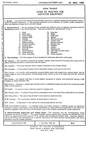
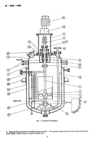
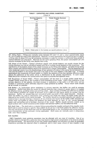
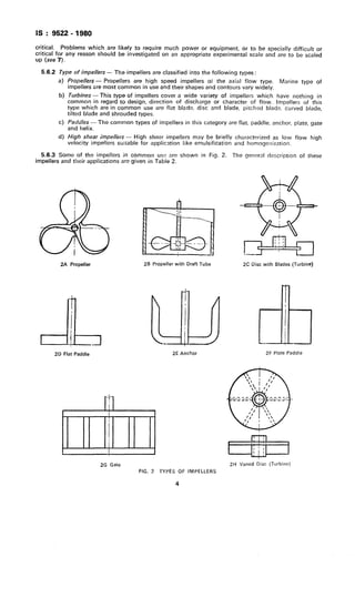
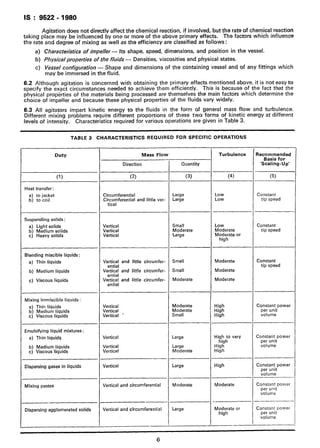
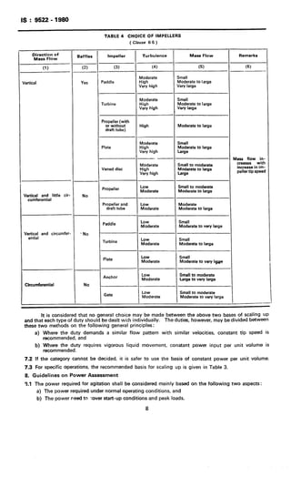
This document provides information on an Indian standard code of practice for agitator equipment. It includes:
1) An introduction that outlines the standard's scope in recommending capacities and requirements for agitator equipment including impellers, power assessment, drives, bearings, and shaft design.
2) Details on vessel sizes and recommended capacities in table format.
3) Descriptions and applications of common impeller types like propellers, turbines, paddles and others.
4) Guidelines for selecting an impeller and scaling up operations based on physical processes like mass transfer, heat transfer and dispersion involved in agitation.
The document discusses agitator design and selection. It describes single duty agitators that provide either flow or shear, and multi-duty agitators. The selection of impeller type, diameter, and speed depends on the process requirements. Impeller options include axial flow, radial flow, and combinations. Proper agitator design also considers mechanical design aspects like power requirement, shaft, and seals. A universal mixer is described that can handle a wide range of mixing duties through adjustable flow and shear.
Reciprocating compressors compress gases via pistons moving inside cylinders. They have high pressure pulsations and can surge if not regulated properly. Flow rate in reciprocating compressors is regulated through variable clearance volumes, variable speed, bypass valves, or suction valve unloaders. Calculating intermediate pressures in multi-stage reciprocating compressors involves determining the common pressure ratio between stages using the overall pressure ratio and number of stages.
Heat exchangers transfer heat from one fluid to another without direct contact between the fluids. The most common type is the shell-and-tube heat exchanger, which consists of tubes in a shell container. Fluids flow inside the tubes and outside in the shell. Other key types include double-pipe exchangers, plate-and-frame exchangers, air-cooled exchangers, and spiral exchangers. Spiral exchangers have two fluids spiraling in opposite directions to enhance heat transfer.
This document is a dissertation submitted by Kuan, Siew Yeng to the University of Southern Queensland in fulfillment of the requirements for a Bachelor of Engineering (Mechanical Engineering) degree. The dissertation focuses on designing a new floating roof tank. It provides background on floating roof tanks, relevant design codes and standards, and discusses design considerations and methods for the shell, roof, fittings and accessories. The goal is to develop basic rules and procedures for designing, constructing and operating floating roof tanks based on a case study.
Calculation of Flowrate and Pressure Drop Relationship for Laminar Flow using...Usman Shah
This document discusses the relationships between flow rate, pressure drop, and shear stress for laminar flow in pipes. It provides equations to calculate flow rate from shear stress and pressure drop data. The key relationships are:
1) Pressure drop is directly proportional to flow rate for laminar flow.
2) Shear stress at the wall is related to pressure drop by an equation involving pipe diameter and length.
3) Shear stress decreases linearly from the wall to the center of the pipe in laminar flow.
4) The flow rate can be calculated from experimentally measured shear stress and pressure drop data using integration methods like Simpson's rule.
The document discusses the design of vessel heads and closures. It describes various types of heads including flat heads, dished heads, elliptical heads, hemispherical heads, and conical heads. It provides equations for analyzing stress and calculating thickness for flat heads depending on their attachment method to the vessel shell. The maximum stress occurs at the edge of a flat head for a simply supported case and at the center for a clamped case.
This document discusses different types of agitators used in pharmaceutical industries and the factors considered in their selection. The main types described are paddle, anchor, radial propeller, propeller, turbine, and helical agitators. Selection depends on viscosity of the fluid and whether mixing time or power consumption is more important. Power required for agitation can be estimated using dimensionless numbers accounting for properties like density, viscosity, agitator speed and diameter.
Agitation and Mixing are two important unit operations used in industries such as Impellers agitators are widely used to circulate the liquid through the vessel in which the dispersion of liquids and gases into other liquids like mixing of stiff paste, elastomers and dry solids powders takes place.
A plate heat exchanger is proposed to cool methanol using brackish water. The initial design requires 97 plates with 48 channels per pass to achieve a heat duty of 4340 kW and overall heat transfer coefficient of 1754 W/m^2°C. Increasing the channels to 60 plates achieves the required coefficient of 1600 W/m^2°C with 121 plates. The pressure drops are estimated to be 0.16 bar for methanol and 0.78 bar for water.
This document provides information about agitators and their selection for food process equipment design. It defines an agitator as something used to stir liquids or mixtures. It then describes various types of agitators like paddles, turbines, screw types, helical blades, anchors, gates, and propellers. It discusses the applications of each type in industries like food processing, paint, and pharmaceuticals. It outlines three main considerations for agitator selection - process requirements, power requirements, and mechanical design. It emphasizes matching the agitator design to the specific process needs, optimizing for efficient power usage, and designing for a long mechanical life.
This document discusses different types of pumps, including their classifications, characteristics, applications, and performance. It describes hydrodynamic/non-positive displacement pumps, which use flow to transfer fluid at relatively low pressure and are generally used for low pressure, high volume applications. It also describes hydrostatic/positive displacement pumps, which have close-fitting components and can create high pressures, making them self-priming. Specific positive displacement pump types like gear, vane, piston and centrifugal pumps are examined in terms of their applications and operating principles. Pump efficiencies including volumetric, mechanical and overall efficiency are also covered.
This document provides training material on heat exchangers, covering their design, operation, maintenance and enhancement. It begins with classifications of different heat exchanger types including tubular, shell and tube, and plate heat exchangers. It then covers basic design equations using the log mean temperature difference (LMTD) method and number of transfer units (NTU) method. The document provides guidance on thermal design considerations, specification sheets, installation, operation, maintenance including repair vs replacement, and troubleshooting of heat exchangers.
The document discusses multi-stage centrifugal pumps. It explains that a multi-stage centrifugal pump has two or more impellers to produce a high head. In a series connection, the total head developed is equal to the number of impellers multiplied by the head developed by each impeller. In a parallel connection, multi-stage pumps are arranged in parallel to discharge a large quantity of liquid, with the total discharge equal to the number of pumps multiplied by the discharge from each pump. Some applications of multi-stage centrifugal pumps include pumping water in high-rise buildings, industrial wash down facilities, fire hydrant systems, boiler feed systems, and irrigation.
Shell and Tube Heat Exchanger in heat TransferUsman Shah
Shell and tube heat exchangers consist of a bundle of tubes enclosed in a cylindrical shell. Fluids flow through either the tubes or shell to facilitate heat transfer between the two fluids. They are widely used in chemical processes due to their ability to achieve a large heat transfer surface area in a compact volume. Key components include tubesheets, baffles, support rods and segmented baffles which direct fluid flow across the tube bundle for efficient heat transfer. Design considerations include allocating the more corrosive or fouling fluid to the tubeside for easier cleaning and maintenance.
1) The document discusses mechanical design of pressure vessels. It covers classification of pressure vessels and design considerations like stresses and stability.
2) Pressure vessels are classified based on thickness-to-diameter ratio into thin-walled and thick-walled vessels. Common shapes are cylindrical and spherical.
3) Design codes specify guidelines for design, materials, fabrication, inspection and testing of pressure vessels. Stresses like circumferential, longitudinal and shear stresses are derived. Failure theories like maximum principal and shear stresses are discussed.
4) Buckling stability is important for thin-walled vessels under compression. Membrane stress equations are provided for common vessel shapes like cylinders, spheres, cones and ellipsoids.
The document discusses different types of compressors used in industries. It describes positive displacement compressors which include reciprocating, rotary, scroll, and liquid ring compressors. Reciprocating compressors can be single acting, double acting, or diaphragm type. Scroll compressors have advantages like high efficiency and lower noise compared to reciprocating compressors. Each compressor type has different applications depending on the process requirements.
This document discusses the process design of shell and tube heat exchangers. It begins by classifying heat exchangers and describing different types of shell and tube heat exchangers such as fixed tube sheet, removable tube bundle, floating head, and U-tube designs. The document then discusses various thermal design considerations for shell and tube heat exchangers, including selections for the shell, tube materials and dimensions, tube layout and count, baffles, and fouling factors. It provides process design procedures and an example problem for designing shell and tube heat exchangers.
Shaft & keys (machine design & industrial drafting )Digvijaysinh Gohil
This document discusses different types of shafts, keys, and their design considerations. It contains the following key points:
1. Shafts can be classified based on their shape (solid or hollow), application (transmitting, machine, spindle), and construction (rigid or flexible).
2. Keys are used to connect rotating machine elements to shafts and prevent relative motion. Common types include rectangular, square, parallel, gib-head, feather, and woodruff keys.
3. Shaft design considers factors like bending moment, shear stress, and material properties. Hollow shafts have higher strength-to-weight ratio than solid shafts of the same size.
Process plant equipment and their operations in petrochemical industrySavanSardhara
Process equipment is used in several applications like reaction purpose, steam power generation, pipelines, water treatment, salt water disposal etc., where chemical or mechanical methods are applied. Some examples of process equipment popularly used in these industries are pumps, boilers, distillation columns,
valves, vessels, filters, coolers, heat exchangers, compressors and piping. Each of these equipment is very important because of their indispensable usage in the working of a process.
Pumps convert mechanical energy to fluid energy and come in various types. The main types are positive displacement pumps, centrifugal pumps, axial flow pumps, and mixed flow pumps. Centrifugal pumps are frequently used in water distribution systems and work by spinning an impeller to push water outward. Axial flow pumps have flow entering and leaving along the pump axis. Multiple impellers can be arranged in series for higher head applications. Pump performance is characterized by curves showing how head and efficiency vary with flow. Total dynamic head and net positive suction head are important concepts for pump sizing and operation. Cavitation can occur if net positive suction head drops too low. Pumps can be arranged in series or parallel to meet different flow
This document discusses mechanical seals which are used to prevent leakage in pumps and other equipment. It describes the need for seals to minimize leakage and prevent toxic fluids from escaping. Both static seals, used between non-moving parts, and dynamic seals, used between moving parts, are covered. Common static seals include gaskets and O-rings, while dynamic seals include gland packings and mechanical contact seals. The document focuses on mechanical seals, explaining their design features such as seal faces, springs, and secondary seals. Different types are classified including single versus multiple spring seals, pusher versus non-pusher seals, and single versus double/tandem arrangements. Materials of construction and operating principles are also summarized.
This document provides an overview and agenda for a two-day course on industrial mixing technology and equipment. The course objectives are to share knowledge and experience on industrial mixing, discuss best practices, and address challenges in the industry. The course will cover fundamentals of mixing liquids, solids, and high viscosity materials. It will discuss mixing theory, equipment selection and design, advances in technology, and solving mixing problems. Case studies will examine challenges in polymer, food, pharmaceutical, and other industries and how customized mixing solutions improved product quality and profits. The document outlines the course contents which include modules on mixing concepts, fluid mixing, solid mixing, scale-up considerations, and mechanical design of mixers. Key mixing concepts like batch vs continuous
1. Agitation involves inducing motion within a material while mixing distributes components randomly.
2. Mixing operations involve various combinations of gases, liquids, and solids and may require agitation to enhance mass and heat transfer between phases.
3. Effective agitation and mixing depends on factors like the impeller type, liquid properties, and vessel design which influence flow patterns within the vessel.
Techno Agencies provides quality liquid agitators for stirring and mixing liquids in various industries. Their agitators consist of a high speed motor mounted on a housing with stainless steel rods and plates. Agitators are available in various specifications to mix different volumes of liquid. They offer advantages like low energy consumption, gentle product treatment, and easy external cleaning. Techno Agencies also provides electric stirrers in various models to mix volumes from 10 to 500 liters, with power consumption ranging from 60 to 2000 watts. They can be contacted for any additional information.
1. Factors to be considered in agitator design include the type and degree of agitation needed, type of agitator and impeller used, tank shape and size, power requirements, and sealing arrangements.
2. Agitation can be vigorous, moderate, or mild depending on the mixing time needed, and the degree of agitation increases with impeller speed and size. Common agitator types include top-entered and side-entered configurations.
3. Important design considerations involve the impeller type and configuration, tank dimensions, power transmission method, and sealing of the agitator shaft. Process requirements dictate the optimal agitator and impeller choices.
This document discusses partnerships, including their formation, operation, and changes in membership. It covers key topics such as:
- What constitutes a partnership and who can be partners
- The partnership agreement and areas it typically addresses
- Accounting for partner capital accounts, initial investments, additional investments, withdrawals, and profit/loss allocation
- Admitting new partners through the purchase of an interest from an existing partner, including potential revaluation of partnership assets
This document provides errata and corrections to the CMAA Specification #70 for top running bridge and gantry cranes. It outlines corrections that need to be made to formulas and equations in sections 70-3 and 70-4 of the specification. In section 70-3 on structural design, corrections are provided for formulas in paragraphs 3.4.6.1 and 3.4.4.2. In section 70-4 on mechanical design, corrections are given for formulas in paragraphs 4.1.1, 4.1.2.1, 4.1.2.2, and 4.1.2.3 relating to mean effective load. It also provides a note that uppercase and lowercase Tau are interchange
Building Structure Project 2 (Taylor's lakeside campus)Ong Seng Peng Jeff
This document provides structural analysis details for a proposed 450 square meter bungalow. It includes:
1) Floor plans, structural plans, and a 3D model of the bungalow structure showing its columns and beams.
2) Calculations of dead and live loads for structural elements like beams, slabs, and columns based on material properties and intended room uses.
3) Beam analysis reports with load distribution plans, bending moment diagrams, and shear force diagrams to determine beam sizes for rooms.
4) A column analysis report estimating column loads and suggesting column sizes.
The analysis follows standard procedures to ensure the bungalow's structural integrity and safety.
1) The document provides instructions for operating and maintaining an overhead crane, including how to start and control the crane pendant, use the emergency stop button, and identifies important safety gear.
2) Operators should run the crane pendant up and down daily when not in use to ensure proper lubrication, check the cable tension regularly, and notify supervision immediately if any wear or unusual behavior is observed.
3) Detailed steps and diagrams are given for starting the crane pendant, controlling its speed, and using the emergency stop button to halt the crane safely. Operators must follow safety protocols and operate the crane at slow, controllable speeds.
Mixing is defined as reducing inhomogeneity to achieve a desired process result, where the inhomogeneity can be of concentration, phase, or temperature. Agitation accomplishes mixing of phases and enhances mass and heat transfer between phases and external surfaces. Basic design factors for mixing include impellers, vessel dimensions, impeller placement, and operating parameters like speed. Mixing occurs through distribution, which transports materials throughout the vessel via bulk currents, and dispersion, which facilitates rapid transfer through the creation of eddies down to the Kolmogorov scale of mixing. The mixing time is considered the time for the concentration to differ from the final concentration by less than 10% after initial segregation.
Contoh perkataan digraf, diftong, konsonan dan vokal bergandingCik Lyeen
The document defines and provides examples of three phonological terms in Malay:
1) Diphthongs - two adjacent vowel letters pronounced as a single blended sound, like "ai" in "zaitun".
2) Digraphs - two adjacent consonant letters pronounced as a single sound, like "kh" in "khas".
3) Vowel combinations - two adjacent vowel letters that are pronounced separately, like the "ai" in "air".
Tables with examples of words containing each type of phonological component are included for additional illustration.
This document provides an overview of Lovejoy/Sier-Bath continuous sleeve and flanged sleeve couplings. It describes the features and benefits of both types of couplings, including their ability to accommodate misalignment and end float. It also lists and briefly describes several standard types of couplings for both continuous sleeve (C types) and flanged sleeve (F types) series. Safety instructions are provided on properly selecting, installing, and operating these power transmission products.
This document discusses mixing and blending in the pharmaceutical industry. It defines mixing as a unit operation aimed at reducing non-uniformity in a material's properties. The main goals of mixing are producing a uniform blend and ensuring each component is in contact with the others. Mixing can involve single or multiphase systems and the types of mixtures are positive, negative, and neutral. Key mixing mechanisms for liquids include bulk transport, turbulent flow, laminar flow, and molecular diffusion. Common mixing equipment uses impellers or paddles to induce flow. Problems in mixing include segregation which depends on particle properties. Proper equipment selection considers material properties and processing factors.
The document describes the design of a batch stirred tank reactor for producing industrial alcohol through fermentation. Key details include:
- The reactor will be a jacketed, stirred tank reactor with a volume of 377m3, 10m height, 6.8m diameter, and carbon steel construction.
- It will operate at 32°C and 1.8 atm with a 52 hour batch time and use a torispherical head.
- Cooling will be provided by a 17m2 jacket using 33 tons/hr of cooling water from 20-28°C.
- Agitation will be from three 6-bladed impellers 2.2m in diameter running at 44 RPM and requiring 60
The following presentation is only for quick reference. I would advise you to read the theoretical aspects of the respective topic and then use this presentation for your last minute revision. I hope it helps you..!!
The document provides safety guidelines for operating overhead cranes and hoists. It states that equipment must be inspected daily for wear and damage before use. Operators should warn others to stay clear of lifted loads and never allow anyone to ride the hook or load. Loads should be lifted smoothly and directly below the hoist, and brakes should be tested when lifting near maximum capacity. Cranes should never be left unattended while loads are suspended.
This was my pharmaceutics presentation for mixing. Provides definitions, mechanism, types of mixers etc.
P.S: I am not the sole presenter. Ideas are from my two other colleagues as well.
The autoclave uses steam under pressure to sterilize laboratory equipment and supplies. It operates by generating saturated steam at high temperatures, typically 121°C, which is able to destroy all microbial life, including bacterial spores. There are two main types - horizontal autoclaves that use downward displacement of air, and vacuum-assisted autoclaves that remove air via vacuum before introducing steam. Proper loading and maintenance are required to ensure effective sterilization.
The document discusses characterization of solid suspension in mechanically agitated vessels. Experiments were conducted using four pitch and six pitch turbine impellers to dissolve alum of different mesh sizes (4, 6, 8, 10 mm) in water. It was found that as agitation time increased, the weight of dissolved alum decreased. The highest power consumption was required for the 10 mm mesh size and lowest for the 4 mm size. The four pitch impeller required more power than the six pitch impeller. Increasing the mesh size or time of agitation increased the weight of alum dissolved.
The document summarizes an experiment to determine the relationship between speed of rotation, diameter, and power requirement for baffled and unbaffled tanks. Data showed that power number decreases as Reynolds number increases, and is higher for baffled tanks than unbaffled tanks under turbulent conditions. The power requirement increases with impeller size but operating at very high speeds can lead to inefficiency through vortex formation.
This document provides recommendations for the design of trash racks installed at water intake entrances. It contains information on:
1. Classifying trash racks by their construction features and installation methods into removable section racks, racks secured with bolts, and racks bolted in place below the water line.
2. Factors to consider when selecting a trash rack type, including accessibility, expected debris size, and cleaning mechanism.
3. Design recommendations such as rack inclinations, flow velocities, hydraulic loss calculations, structural design considerations, and trash bar spacing formulas tailored for different turbine types.
4. Structural design should consider loads from differential hydraulic head and partial clogging, with materials usually being structural steel.
This document establishes minimum standards for sedimentation tanks used at construction dewatering sites that discharge wastewater to the King County sanitary sewer system. It summarizes literature on sedimentation tank design principles and reviews two common portable sedimentation tank models. Minimum standards are selected for hydraulic retention time (1.5 hours), overflow rate (800-3,000 gallons per day per square foot), aspect ratio (3:1 to 5:1 length to width), and maximum sediment accumulation (18.75-37.5% of tank height). Tanks meeting these criteria along with proper monitoring of sediment levels are deemed the minimum treatment required for construction dewatering wastewater containing settleable solids.
It is hard to imagine how far we would be if we had just listen to the true masters of the Game Kaj Lavender & Jens Kappel these 2 men would have saved our world and oceans, here is just one of Oskar's examples his is Kajs son, SeaBus was and is so real it is truly a question of treason ..!
Design Calculation of Penstock and Nozzle for 5kW Pelton Turbine Micro Hydrop...ijtsrd
This paper provides to design penstock and nozzle for 5kW Pelton turbine micro hydropower plant for household applications. The other objective of this paper is to develop the life inhabitant living in rural areas by the supply of required electricity from the natural resources of water to provide the development of design calculation of penstock, to reduce the environmental fuel. Water from the storage reservoir is flow through penstock to the power house. Penstocks carry the water under pressure from the storage reservoir to the turbine. When the turbine is operating without a correct penstock, the required power cannot be produced efficiency since water coming from penstock is not capable to reach into the runner in full amount due to splash sideways due to friction. Therefore selection of material of penstock is necessary to install in the turbine. In this paper, the basic theory of hydropower penstock and nozzle are calculated. Zin Mar Chan "Design Calculation of Penstock and Nozzle for 5kW Pelton Turbine Micro Hydropower Plant" Published in International Journal of Trend in Scientific Research and Development (ijtsrd), ISSN: 2456-6470, Volume-3 | Issue-5 , August 2019, URL: https://www.ijtsrd.com/papers/ijtsrd26552.pdfPaper URL: https://www.ijtsrd.com/engineering/mechanical-engineering/26552/design-calculation-of-penstock-and-nozzle-for-5kw-pelton-turbine-micro-hydropower-plant/zin-mar-chan
This document discusses recent trends and the future of ultra deepwater oil field developments. It summarizes that developments in ultra deepwater have very high costs, prompting companies to consider more standardized and innovative solutions. Subsea wells and FPSOs have become the standard for field development below depths of around 2500-3000 meters. New technologies like subsea separation, direct electrical heating of flowlines, and subsea power distribution are being successfully implemented and will likely become more common. Future field developments are expected to utilize more standardized components coupled with innovative technologies to reduce costs and maximize recovery in ultra deepwater environments over the next 5-10 years.
The document discusses key considerations for designing a shaft system for an underground mine. It addresses the interrelation of the shaft subsystem with other mine systems like ventilation, dewatering, and transport. The main elements of a shaft system include the headframe, winder house, shaft collar, fan drift, fittings and conveyances. Designing the shaft requires a multidisciplinary approach and consideration of functional requirements, geological conditions, operational parameters, and statutory regulations. Choice of the winding system, conveyance type, and winder location are important design decisions.
IRJET- Design of a Three-Phase AXIAL FLUX Self-Excited Induction Generato...IRJET Journal
This document describes the design of a three-phase axial flux self-excited induction generator for use in industrial discharge channels to generate electricity from water flows. It discusses using a crossflow hydrokinetic turbine coupled to the generator to convert the kinetic energy of water into rotational energy. The generator would use an axial flux self-excited induction design which has advantages over traditional radial flux designs for applications requiring high torque or a compact design. It proposes that combining a crossflow turbine with an axial flux generator into a single floating unit could efficiently generate electricity from water flows with low environmental impact.
The document discusses various aspects of distillation column design including tray types, sizing considerations, flooding, efficiency, and special design features. It provides details on perforated, valve, bubble cap, and chimney trays as well as concepts like weir loading, distribution, and orientation of components. Tray selection depends on factors like volatility, thermal stability, corrosion resistance, and desired throughput. Proper design aims to maximize capacity while avoiding issues that could reduce efficiency or damage equipment during start-up.
- Energy efficiency technologies can significantly reduce energy usage and costs for ships through innovations like hull design improvements, efficient propulsion systems, waste heat recovery, and alternative fuels.
- Examples of promising technologies include air lubrication systems to reduce hull resistance, optimized propeller and rudder designs, waste heat recovery systems, and use of sails or kites to capture wind power.
- Adopting a portfolio of these technologies through concepts like the low loss power distribution system, combined diesel-electric propulsion, or efficient auxiliary systems can lower energy usage on ships by 5-30% depending on the vessel type and operational profile.
This document evaluates the effect of different blade shapes on the performance of six-bladed disk turbines used for gas-liquid dispersion. Streamlined blade shapes were found to reduce power draw sensitivity to gas flow rate compared to standard Rushton turbines, while providing similar mixing and mass transfer rates. Specifically:
1) Blade streamlining through semicircular, angled, and lancet shapes led to lower ungassed power numbers, higher gas flow before flooding, and less variation in power with gas rate.
2) At the same power input and gas velocity, modified and Rushton turbines provided equivalent mixing time, gas holdup, and mass transfer coefficients.
3) Performance correlates with specific power
The document provides an overview of hydraulics actuation systems used in heavy machinery. It discusses how fluid power works through Pascal's law and hydraulic leverage to amplify force. Key components of hydraulic systems are described, including reservoirs, filters, pumps, motors, accumulators, cylinders, and control valves. Common applications like earthmoving equipment, presses, and rollercoasters are highlighted. Diagrams illustrate the configuration and flow of components in hydraulic circuits.
Vertical axis Darrieus water turbine, very suitable for use in river flow in the utilization of the kinetic energy. Darrieus H type hydrokinetic turbines are electromechanical energy converters that generate electricity from harness kinetic energy of flowing water to generate electricity. The design water speed is 1.5m s , tip speed ratio 4 and the final power output is designed to be 100W through water turbine. The designed water turbine has 3 blades. Electricity is generated by using Darrieus H type hydrokinetic turbine. Blade design is made of fiber and the chord length of 0.0742m. The diameter and the height of turbine are 0.354m and 0.531m with two circular end plates. Steel shaft has 7.85mm in diameter. Hydrofoil NACA 0018 is chosen based on max CL CD ratio at angle of attack 10'. The design hydrokinetic turbine can be used for pico hydro generation in rural communities non connected to electricity. This research can provide to generate the electricity Darrieus hydrokinetic Turbine with low cost and local materials. Ei Ei Mon "Design of Low Head Hydrokinetic Turbine" Published in International Journal of Trend in Scientific Research and Development (ijtsrd), ISSN: 2456-6470, Volume-3 | Issue-5 , August 2019, URL: https://www.ijtsrd.com/papers/ijtsrd27865.pdfPaper URL: https://www.ijtsrd.com/engineering/mechanical-engineering/27865/design-of-low-head-hydrokinetic-turbine/ei-ei-mon
Global Domination Set in Intuitionistic Fuzzy Graphijceronline
International Journal of Computational Engineering Research (IJCER) is dedicated to protecting personal information and will make every reasonable effort to handle collected information appropriately. All information collected, as well as related requests, will be handled as carefully and efficiently as possible in accordance with IJCER standards for integrity and objectivity.
Surge Pressure Prediction for Running Linerspvisoftware
This white paper will review the engineering analysis behind trip operations for different pipe end conditions. The author will discuss the controlling parameters affecting surge pressure using SurgeMOD. There are 2 aspects of the surge and swab pressure analysis: one is to predict surge and swab pressure for a given running speed (analysis mode), while the other one is to calculate optimal trip speeds at different string depths without breaking down formations or causing a kick at weak zone (design mode). This article will address both issues. Examples of running liners in tight tolerance wellbore will be analyzed.
This document provides an overview of the Archimedean screw as a low head hydropower generator. It discusses the basic design and operation of Archimedean screws, including their rotating helical shape supported by bearings. Archimedean screws can operate at heads as low as 1 meter and flows up to 15 cubic meters per second. They typically have an efficiency around 80% and can tolerate debris well due to their large dimensions. The document also notes some advantages of Archimedean screws for hydropower such as their fish friendliness and simpler civil works compared to other turbine types.
International Refereed Journal of Engineering and Science (IRJES)irjes
The core of the vision IRJES is to disseminate new knowledge and technology for the benefit of all, ranging from academic research and professional communities to industry professionals in a range of topics in computer science and engineering. It also provides a place for high-caliber researchers, practitioners and PhD students to present ongoing research and development in these areas.
DESIGN AND FABRICATION OF DISC TYPE HYBRID TURBINE-PUMPDenny John
This document summarizes the design and testing of a hybrid disc turbine-pump system. The system integrates fluid transportation and power generation using a single circular assembly of rotating discs. Computer-aided design was used to model the system, and computer fluid dynamics simulations were performed to analyze fluid flow. Experimental testing of the pump showed it could generate head up to 10.2 meters. Testing of the turbine portion involved measuring RPM output at different flow rates and controlling mass flow to achieve desired angular velocities to generate power. Flow simulation software was used to further analyze fluid behavior in the pump design.
This document provides a summary of an Indian standard specification for steel pipe flanges. It includes:
1) The scope which outlines the different types of steel pipe flanges covered such as integral, welding neck, plate, screwed boss, slip-on boss, and loose flanges.
2) The material requirements including specifications for carbon steel, carbon molybdenum steel, chrome-molybdenum steel, and requirements for bolts and nuts.
3) The classification of flanges into different pressure-temperature classes ranging from Classes 0-1 to 16-0.
4) Tables providing material specifications and allowable stress values for different materials at various design temperatures.
Is 456.2000 plain and reinforced concreteVishal Mistry
This document provides information on the disclosure of a public safety standard by the Bureau of Indian Standards to promote transparency and access to information. It aims to make this standard available, especially to disadvantaged communities and those pursuing education. The standard is IS 456 (2000) related to plain and reinforced concrete code of practice. The document also contains quotes on the right to information and the importance of knowledge.
The document discusses the benefits of exercise for mental health. Regular physical activity can help reduce anxiety and depression and improve mood and cognitive function. Exercise causes chemical changes in the brain that may help protect against mental illness and improve symptoms.
Is 919.1.1993 iso systems of limits and fits,Vishal Mistry
This document provides information on an Indian standard regarding the ISO system of limits and fits. It establishes the bases of the ISO system including standard tolerances and fundamental deviations. The standard defines key terms used such as shaft, hole, size, deviation, tolerance, and fits. It provides graphical representations of tolerances and deviations. The standard aims to promote accuracy and consistency in manufacturing parts that interface through standardized tolerances and limits.
This document is the Indian Standard for foundation bolts. It provides specifications for foundation bolts sized M8 to M72. It specifies requirements for dimensions, tolerances, material, mechanical properties, marking, and other technical supply conditions. Foundation bolts are designed for use in masonry and concrete foundations. The standard specifies a property class of 4.6 and allows for hot-dip galvanized coatings if agreed by the supplier and purchaser. It provides typical shank forms and their dimensions in an appendix. The standard is intended to promote the dissemination of public safety information to disadvantaged communities and those engaged in education and knowledge.
Is 4000 high strength bolts in steel structuresVishal Mistry
This document provides guidelines for the use of high-strength bolts in steel structures. It covers the design, fabrication, assembly and inspection of structural joints using high-strength bolts that meet the specifications in IS 3757. The document establishes requirements for bolt size and properties, permissible tensile and shear forces, types of joints (friction and bearing), surface preparation, hole size, tightening methods and quality control. It seeks to enable the effective and safe use of high-strength bolts in structural connections as an alternative to welding.
This document introduces an attached publication of a public safety standard by the Bureau of Indian Standards regarding hexagon fit bolts. It summarizes that the standard is being made publicly available to promote transparency and accountability as well as timely access to information, especially for disadvantaged communities and those in education. The attached standard regards test methods for hexagon fit bolts.
Is 2688.2009 insulated ss horizontal tankVishal Mistry
This document is the Indian Standard for insulated stainless steel horizontal milk storage tanks. It specifies the requirements and provides details for milk storage tanks with capacities of 5,000, 10,000, and 15,000 litres. The key points are:
- The tanks consist of a stainless steel inner shell, suitable insulation material (like polyurethane foam or expanded polystyrene) in the annular space between the inner and outer shells, and an outer shell.
- The inner and outer shells are made of stainless steel and have minimum thickness requirements. Welded joints must be smooth.
- Insulation is provided in three layers between the inner and outer shells to maintain temperature.
-
This document is the Indian Standard IS 2102 (Part 1) from 1993 that specifies general tolerances for linear and angular dimensions without individual tolerance indications in four tolerance classes (fine, medium, coarse, very coarse). It applies to dimensions of parts produced by metal removal or sheet metal forming. The standard provides tables with permissible deviations for linear dimensions, broken edges, and angular dimensions according to the tolerance class and nominal size range. It specifies that drawings should refer to this standard and indicate the tolerance class to apply the general tolerances. Features exceeding the general tolerance are not cause for automatic rejection if function is not impaired.
Is 1161.1998 steel tubes for structural purposesVishal Mistry
This document is the Indian Standard for steel tubes used for structural purposes. It specifies the requirements, dimensions, weights and tolerances for hot finished welded, hot finished seamless, and electric resistance welded steel tubes. The standard defines three classifications (light, medium, heavy) based on wall thickness and three grades (YSt 210, YSt 240, YSt 310) based on yield strength. Table 1 provides the standard sizes, weights, and geometric properties. The steel tubes must meet the material specifications in Table 3 and dimensions/tolerances outlined in the standard.
Is 1161.1998 steel tubes for structural purposesVishal Mistry
This document is the Indian Standard for steel tubes used for structural purposes. It specifies the requirements, dimensions, weights and tolerances for hot finished welded, hot finished seamless, and electric resistance welded steel tubes. The standard defines three classifications (light, medium, heavy) based on wall thickness and three grades (YSt 210, YSt 240, YSt 310) based on yield strength. Table 1 provides the standard sizes, weights, and geometric properties. The steel must meet the specifications in Table 3 and tubes are to be supplied in the conditions shown. Tolerances for dimensions and weights are also provided.
Is 919.1.1993 iso systems of limits and fits,Vishal Mistry
This document provides information on an Indian standard regarding the ISO system of limits and fits. It establishes the bases of the ISO system including standard tolerances and fundamental deviations. The standard defines key terms used such as shaft, hole, size, deviation, tolerance, and fits. It provides graphical representations of tolerances and deviations. The standard aims to promote accuracy and consistency in manufacturing parts that interface through standardized tolerances and limits.
The document discusses the benefits of exercise for mental health. Regular physical activity can help reduce anxiety and depression and improve mood and cognitive function. Exercise causes chemical changes in the brain that may help protect against mental illness and improve symptoms for those who already suffer from conditions like anxiety and depression.
Electric vehicle and photovoltaic advanced roles in enhancing the financial p...IJECEIAES
Climate change's impact on the planet forced the United Nations and governments to promote green energies and electric transportation. The deployments of photovoltaic (PV) and electric vehicle (EV) systems gained stronger momentum due to their numerous advantages over fossil fuel types. The advantages go beyond sustainability to reach financial support and stability. The work in this paper introduces the hybrid system between PV and EV to support industrial and commercial plants. This paper covers the theoretical framework of the proposed hybrid system including the required equation to complete the cost analysis when PV and EV are present. In addition, the proposed design diagram which sets the priorities and requirements of the system is presented. The proposed approach allows setup to advance their power stability, especially during power outages. The presented information supports researchers and plant owners to complete the necessary analysis while promoting the deployment of clean energy. The result of a case study that represents a dairy milk farmer supports the theoretical works and highlights its advanced benefits to existing plants. The short return on investment of the proposed approach supports the paper's novelty approach for the sustainable electrical system. In addition, the proposed system allows for an isolated power setup without the need for a transmission line which enhances the safety of the electrical network
Introduction- e - waste – definition - sources of e-waste– hazardous substances in e-waste - effects of e-waste on environment and human health- need for e-waste management– e-waste handling rules - waste minimization techniques for managing e-waste – recycling of e-waste - disposal treatment methods of e- waste – mechanism of extraction of precious metal from leaching solution-global Scenario of E-waste – E-waste in India- case studies.
Literature Review Basics and Understanding Reference Management.pptxDr Ramhari Poudyal
Three-day training on academic research focuses on analytical tools at United Technical College, supported by the University Grant Commission, Nepal. 24-26 May 2024
We have compiled the most important slides from each speaker's presentation. This year’s compilation, available for free, captures the key insights and contributions shared during the DfMAy 2024 conference.
International Conference on NLP, Artificial Intelligence, Machine Learning an...gerogepatton
International Conference on NLP, Artificial Intelligence, Machine Learning and Applications (NLAIM 2024) offers a premier global platform for exchanging insights and findings in the theory, methodology, and applications of NLP, Artificial Intelligence, Machine Learning, and their applications. The conference seeks substantial contributions across all key domains of NLP, Artificial Intelligence, Machine Learning, and their practical applications, aiming to foster both theoretical advancements and real-world implementations. With a focus on facilitating collaboration between researchers and practitioners from academia and industry, the conference serves as a nexus for sharing the latest developments in the field.
CHINA’S GEO-ECONOMIC OUTREACH IN CENTRAL ASIAN COUNTRIES AND FUTURE PROSPECTjpsjournal1
The rivalry between prominent international actors for dominance over Central Asia's hydrocarbon
reserves and the ancient silk trade route, along with China's diplomatic endeavours in the area, has been
referred to as the "New Great Game." This research centres on the power struggle, considering
geopolitical, geostrategic, and geoeconomic variables. Topics including trade, political hegemony, oil
politics, and conventional and nontraditional security are all explored and explained by the researcher.
Using Mackinder's Heartland, Spykman Rimland, and Hegemonic Stability theories, examines China's role
in Central Asia. This study adheres to the empirical epistemological method and has taken care of
objectivity. This study analyze primary and secondary research documents critically to elaborate role of
china’s geo economic outreach in central Asian countries and its future prospect. China is thriving in trade,
pipeline politics, and winning states, according to this study, thanks to important instruments like the
Shanghai Cooperation Organisation and the Belt and Road Economic Initiative. According to this study,
China is seeing significant success in commerce, pipeline politics, and gaining influence on other
governments. This success may be attributed to the effective utilisation of key tools such as the Shanghai
Cooperation Organisation and the Belt and Road Economic Initiative.
Presentation of IEEE Slovenia CIS (Computational Intelligence Society) Chapte...University of Maribor
Slides from talk presenting:
Aleš Zamuda: Presentation of IEEE Slovenia CIS (Computational Intelligence Society) Chapter and Networking.
Presentation at IcETRAN 2024 session:
"Inter-Society Networking Panel GRSS/MTT-S/CIS
Panel Session: Promoting Connection and Cooperation"
IEEE Slovenia GRSS
IEEE Serbia and Montenegro MTT-S
IEEE Slovenia CIS
11TH INTERNATIONAL CONFERENCE ON ELECTRICAL, ELECTRONIC AND COMPUTING ENGINEERING
3-6 June 2024, Niš, Serbia
1. Disclosure to Promote the Right To Information
Whereas the Parliament of India has set out to provide a practical regime of right to
information for citizens to secure access to information under the control of public authorities,
in order to promote transparency and accountability in the working of every public authority,
and whereas the attached publication of the Bureau of Indian Standards is of particular interest
to the public, particularly disadvantaged communities and those engaged in the pursuit of
education and knowledge, the attached public safety standard is made available to promote the
timely dissemination of this information in an accurate manner to the public.
इंटरनेट मानक
“!ान $ एक न' भारत का +नम-ण”
Satyanarayan Gangaram Pitroda
“Invent a New India Using Knowledge”
“प0रा1 को छोड न' 5 तरफ”
Jawaharlal Nehru
“Step Out From the Old to the New”
“जान1 का अ+धकार, जी1 का अ+धकार”
Mazdoor Kisan Shakti Sangathan
“The Right to Information, The Right to Live”
“!ान एक ऐसा खजाना > जो कभी च0राया नहB जा सकता है”
Bhartṛhari—Nītiśatakam
“Knowledge is such a treasure which cannot be stolen”
“Invent a New India Using Knowledge”
है”ह”ह
IS 9522 (1980): Code of practice for agitator equipment
[MED 17: Chemical Engineering Plants and Related Equipment]
2.
3.
4. UDC 66.063.8 : 006,76 ( First Reprint OCTOBER 1997 ) IS : 9522 - 1980
Indian Standard
CODE OF PRACTICE FOR
AGITATOR EQUIPMENT
1. Scope_ ~3~sdawnthe standard recommended capacities of agitator equ.ipment and general roquire-
nents of agitatorequipment. It also provides guidelines an the selection of Impeller, power assessment,
jrive and bearing arrangemonts and shaft design.
3. Nomenclature - For the purpose of this standard the different parts of agitator equipment shall be
designated as given in the following table. They are numbered fcu identification in Fig. 1.
1. Shell 15. Gear box
2. Shell cover 16. Motor
3. Vessel flange 17. Draft tube
4. Agitator shaft 18. Baffles
5. Impeller 19. Mechanical seal
6. Impeller hub 20. Lantern ring
7. Rigid coupling 21. Bearing housing
8. Flexible coupling 22. Sparger pipe
9. Stuffing box 23. Headers
10. Stuffing gland 24. Jacket
11. Packing 25. Heating coil
12. Thrust bearing 26. Half tubes (limpet coils)
13. Roller bearing 27. Manhole
14. Drive, mounting 28. Vessel supports
3. Terminology - For the purpose of this standard the following definitions shall apply.
3.1 Agitator - The assembly consisting of impeller, impeller shaft and drive including other parts such as
gland, and bearing used in conjunction with the above.
3.2 /mpe//er - The actual element which imparts movement to the charge (fluid).
3.3 Propeller - A high speed impeller which essentially imparts axial thrust to the fluid.
3.4 Turbine - An impeller with essentially constant blade angle with respect to a vertical plane, over its
entire length or over finite sections, having blades either vertical or set at an angle less than 90” with the
vertical.
3.5 Paddle - An impeller with four or fewer blades, horizontal or vertical, and essentially having a higt
impeller to vessel diameter ratio.
3.6 Anchor - Basically a paddle type impeller which is profiled to sweep the wall of the containing vesse
with a small clearance.
3.7 Baffle - An element fixed inside the vessel tc impede swirl.
3.8 OraLIght Tube - A tubular fitting which is arranged to direct the liquid flow produced by the impeller
3.9 Filling Ratio - The ratio of liquid depth in the vessel to vessel diameter.
3.10 Swirling - The continuous rotation of liquid about a fixed axis.
3.11 Vortex - A depression in the surface of a liquid produced by swirling.
3.12 Fully Baffled Condition - A condition when any further increase in baffling causes no significanl
increase in power consumption ; this may be considered as a state where the liquid swirl in the vessel has
become negligibly small and when all the power input to the impeller expended to create turbulence.
4. Recommended Capacities and Vessel Sizes- The capacities and the corresponding vessel
diameters are shown in Table 1. The vessel diameter shown against each capacity are selected so as to
obtain an approximate filling ratio of I.0 for vessels with torispherical bottorn ends. However, depend-
ing an the filling ratio requirement for a specific application and ather process considerations, the vessel
diameters may be suitably selected.
Adopted 30 May 1980 ~0 November 1980, BIS Gr5
BUREAU OF INDIAN STANDARDS
MANAK BHAVAN, 9 BAHADUR SHAH ZAFAR MARG
NEW DELHI 110002
( Reaffirmed 2006 )
5. IS : 9522 - 1980
-_
-
.“,
FIG. 1 AGITATOR ASSEMBLY
-cl26
5. General Requirements of Mixing Equipment -The general requirements of the mixing equipment
given below mainly relate to vertical vessels only.
2
6. IS : 9522 - 1980
TABLE 1 CAPACITIES AND VESSEL DIAMETERS
(Clause 4)
-
-
Nominal Capacity
Litres
(1)
250
400
630
(750)
1 000
(1 250)
1 600
(2 000)
2 500
(3 200)
4 000
(5 000)
6 300
(8 000)
10000
Vessel Outside Diameter
mm
(2)
700
800
1 000
1 000
1 200
(1 300)
1 400
(1 500)
1 600
(1 700)
1 800
(2 000)
2100
(2 300)
2 400
Note-Values given in the brackets are second preference values.
5.1 Filling Ratio - Filling ratio normally varies between 0.5 and 1.5 and a value approximately equal
to 1.0 is suitable for most of the applications. However, in some applications like dispersing gas in a liquid,
a filling ratio of about 2.0 may be sometimes necessary in order to maintain a sufficiently long period of
contact between gas and liquid. Normally for the same agitating effect, the power consumption per unit
volume increases as the filling ratio departs from unity.
5.2 Shape of the Vesse/- Vertical cylindrical vessels with dished bottoms are usually chosen for the
mixing operation but use of cylindrical vessels with-flat or shallow coned-bottoms is not uncommon. The
significance of the bottom shape of the vessel increases as the filling ratio reduces, and other things being
equal vessels with dished bottoms tend to be economical in power consumption. The flat bottomed and
cone-bottomed vessels have the disadvantage of low agitation efficiency in the corner formed between the
wall and flat bottom in the former case and in the apex of the cone bottom in the latter case. In mixing
applications like suspension of heavy solids in a liquid, the presence of the low agitation efficiency areas
allows the settlement of the solids which is detrimental to the process requirements. In such cases,
fillets should be inserted in the corners and in the apex to avoid the low agitation areas.
5.3 Roughness of Vesse/ Walls - Power consumption will be more in a rough walled vessel than a
smooth walled vessel due to the increase in local turbulence at the walls. Even if the turbulence is the
primary objective of the agitator, the local increase in turbulence at the walls is of little value and an
increase in turbulence when definitely required is best achieved by baffles. Hence vessel walls should
be as smooth as possible.
5.4 Baffles- In applications where turbulence is primary requisite, the baffles are used to promote
turbulence. Baffles also allow the system to absorb relatively large amount of power where it is needed
for effective mixing, avoiding vortex and swirling action. Four numbers of baffles are sufficient to achieve
a fully baffled condition for vessels of diameter up to 2 500 mm and above which six number may be
necessary. Baffles are straight flats and normally of width one-tenth of the vessel diameter. However,
when the baffles are used in conjunction with a heating coil inside the vessel, the baffle width may be
reduced to one-twelfth of the vessel diameter. The baffles should be mounted vertically and radially in a
vessel at equal spacings leaving a clearance of one-third to one-fourih of the baffle width between the
vessel walls and baffles to reduce and tendency for solid deposits to form in the corners between
vessel wall and baffles and to facilitate cleaning of the vessel. Baffles should normally extend up to
liquid surface with a small clearance at the bottom end between baffles and flat bottomed ends.
5.5 Draft Tube - The draft tube is a tubular fitting surrounding the impeller and part of the impeller shaft.
Draft tube is used to ensure a specific flow pattern to be set up in the fluid system for effective mixing.
The size and location of the draft tube shall be determined based on the mechanical and mixing perform-
ance characteristics of the particular mixing application. Draft tubes are normally used in conjunction
with axial flow impellers.
6.6 Impellers
5.6.1 Essentially most agitating operations may be effected with any type of impellers. Use of an
impeller which is not best for a particular duty may result in high power consumption or be slow to achieve
the required results. For equipment of low cost, power consumption and efficiency are often of secondary
importance provided the required effect is produced, and in such cases choice of best impeller is not
3
7. IS : 9522 - 1980
critical. Problems which are
critical for any reason should
up (see 7).
likely to require much power or equipment, or
be investigated on an appropriate experimental
to be specially difficult or
scale and are to be scaled
5.6.2 Type of impellers - The impellers are classified into the following types :
a)
b)
cl
d)
Propellers - Propellers are high speed impellers oi the axial flow type. Marine type of
impellers are most common in use and their shapes and contours vary widely.
Turbines -This type of impellers cover a wide variety of impellers which have nothing in
common in regard to design, direction of discharge or character of flow. Impellers of this
type which are in common use are flat blade, disc and blade, pitched blade, curved blade,
tilted blade and shrouded types.
Paddles - The common types of impellers in this category are flat, paddle, anchor, plate, gate
and helix.
High shear impellers - High shear impellers may be briefly characterized as low flow high
velocity impellers suitable for application like emulsification and homogenization.
5.6.3 Some of the impellers in common usz) are shown in Fig. 2.
impellers and their applications are given in Table 2.
The general clescription of these
2A Propeller
LI!
2D Flat Paddle
2B Propeller with Draft Tube
2E Anchor
2G Gate
FIG. 2 TYPES OF IMPELLERS
4
2C Disc with Blades (Turbine)
I
&2F Plate Paddle
J
1-1
2H Vaned Disc (Turbine)
8. IS : 9522 - 1980
TABLE 2 IMPELLERS IN COMMON USE
(Clause 5.6.3)
Type of Impeller
(1)
Propeller
Propeller with draft
tube
Turbine
Description Application
(2) (3)
Wide variety in form, possible form simple twis- Basically high speed agitator but operates over
ted arms to properly formed marine propellers. wide speed range. Mass flow is vertical
NO standardization of pitch or number of and little circumferential. Economical on
blades between manufacturers. Marine tyoe power. Suitable for duties where agitation
propellers are usually less than 1/4th of the is .not very intense and unsuitable for high
vessel diameter. viscosities. Much used for relatively small
scale blending operations.
--
Propeller fitted below or iust inside the lower Applications similar to those of simple pro-
end of draft tube. Baffles may be fitted in peller, but more positive turnover of liquid
the draft tube. Top of draft tube may be just and its flow through the impeller is ensured
above or below the standing liquid level. which is advantageous in wetting out some
solids and mixing some immiscible liquids.
By suitable location of the top level of the
draft tube, a pouring action which will drown
floating solids is achieved.
--
Flat disc with blades attached to periphery. Generally moderately fast running agitator and
Similar effects are produced with the same versatile. Particularly suitable for high in-
number of blades directly attached to a boss. tensities of agitation and high power inputs.
Overall diameter of the impeller is usually Recommended for applications where gas
1/3rd of the vessel diameter. dispersion combined with intense agitation is
required.
Flat paddle
Anchor
_
Single flat blade (two arms) usually about 2/3rd
of the vessel diameter.
Genya$$w speed ,agitat?l capable of pro-
htgh rntensltres of agltatlon,
especially when baffled.
-- --
Agitator following closely the contour of the A large low speed agitator, useful where the
vessel normally with a clearance of 25 mm to wa!l film must be disturbed like in heat
40 mm between impeller and vessel wall. transfer to viscous liquids from jacket, or
where build up of solids on the wall is likely,
as in crystallization. At low speeds has a
very gentle action and will prevent caking in
the bottom of vessel without vigorous agita-
tion elsewhere. Widely used in enamelled
equipment.
Plate A square or rectangular plate bisected by the Similar applications to those of flat paddle,
shaft on which it is mounted. Length usually but allows more clearance for heating coils,
1/3rd to l/2 of that of vessel diameter. fittings, etc, in the vessel. Where the depth
of the plate is large relative to liquid depth,
vertical movement of the liquid is less than
that of a paddle of equivalent power.
Gate An assembly of horizontal and vertical strips A large .low speed agitator of similar applica-
sometimes with diagonal bracing. Normally tions to those of anchor, but normally allows
of length approaching vessel diameter and of more clearance for coils and internal fittings
depth about l/2 to 3/4th of overall length. in the vessel. It does not have the close
sweeping effect of an anchor on the vessel
walls and boss.
~.
Vaned disc A circular disc, usually 1/6th to l/2 of vessel A small or moderately sized high speed agitator,
diameter with radial vanes 1/6th to 1/24th limited usually to gas dispersion. The gas is
of disc diameter deep on its underside. fed under the centre of the disc. The power
consumption without gas flow will be much
higher than when gas is on, and drive shop’ld
be adequate to cover the gasless condition.
6. Guidelines for the Selection of Impeller and Scaling Up
6.1 Agitation - In all applications of agitation, the primary effects are concerned with one or more of the
following three physical processes :
a) Mass transfer;
b) Heat transfer; and
c) Dispersion of solids, liquids or gases.
5
9. IS:9522 - 1980
Agitation does not directly affect the chemical reaction, if involved, but the rate of chemical reaction
taking place may be influenced by one or more of the above primary effects. The factors which influence
the rate and degree of mixing as well as the efficiency are classified as follows:
a) Characteristics of impeller - Its shape, speed, dimensions, and position in the vessel.
b) Physical properties of the fluids - Densities, viscosities and physical states.
c) Vessel configuration - Shape and dimensions of the containing vessel and of any fittings which
may be immersed in the fluid.
6.2 Although agitation is concerned with obtaining the primary effects mentioned above, it is not easy to
specify the exact circumstances needed to achieve them efficiently. This is because of the fact that the
physical prop&ies of the materials being processed are themselves the main factors which determine the
choice of impeller and because these physical properties of the fluids vary widely.
6.3 All agitators impart kinetic energy to the fluids in the form of general mass flow and turbulence.
Different mixing problems require different proportions of these two forms of kinetic energy at different
levels of intensity. Characteristics required for various operations are given in Table 3.
TABLE 3 CHARACTERISTICS REQUIRED FOR SPECIFIC OPERATIONS
Duty Mass Flow Turbulence Recommended
Basis for
‘Scaling-Up’
(1)
Heat transfer:
a) to jacket
b) to coil
Suspending solids:
a) Light solids
b) Medium solids
c) Heavy solids
Blending miscible liquids :
a) Thin liquids
b) Medium liquids
c) Viscous liquids
Mixing immiscible liquids :
a) Thin liquids
b) Medium liquids
c) Viscous liquids
Emulsifying liquid mixtures :
a) Thin liquids.
b) Medium liquids
c) Viscous liquids
Dispersing gases in liquids
Mixing pastes
Dispersing agglomerated solids
Direction Quantity
(3)(2) (4) (5)
Circumferential
Circumferential and little ver-
tical
Large
Large
Low
Low
Low
Moderate
Moderate or
high
Vertical
Vertical
Vertical
Small
Moderate
Large
Small
Small
Moderate
Moderate
Moderate
Moderate
Constant
tip speed
Vertical and little circumfer-
ential
Vertical and little circumfer-
ential
Vertical and little circumfer-
ential
Moderate
Moderate
Small
High
High
High
Constant power
per unit
volume
Vertical
Vertical
Vertical *
Vertical Constant power
per unit
volume
Large
Large
Moderate
High to very
high
High
High
High
Vertical
Vertical
Vertical Large Constant power
per unit
volume
_.
ModerateVertical and circumferential Constant power
per unit
volume
Moderate
Moderate or
high
Constant power
per unit
volume
Vertical and circumferential Large
II
6
10. IS:9522 - 1980
6.4 General Considerations for Selection of Impellers
6.4.1 The following considerations shall be borne in mind for the power selection of the impeller.
6.4.1 .l Baffles - Baffles have the effect of reducing mass flow and increasing turbulence. The
formation of vortex is prevented as circumferential flow is suppressed. They are useful where the appli-
cation requires high turbulence and capable of absorbing high power at relatively low speeds of rotation.
6.4.1.2 Speed of rotation - The tip speeds of all impellers are nearly same for the same agitating
effects except in the case of propellers and anchors. Consequently, for a given effect, smaller agitator
needs to be run at higher speeds and if small agitators are desired the effects of higher speed on erosion,
bearing wear, gland difficulties, vibration and allied effects should be tolerated.
6.4.1.3 Impeller size - For the same vessel a large agitator operating at low speed products relatively
more mass flow and less turbulence than a smaller but geometrically similar agitator which operates at
high speeds and transmits the same power.
6.4.1.4 Number of impellers - Large filling ratios are not recommended but where used should in
general have one impeller for each vessel diameter of liquid depth.
6.4.1.5 Power and viscosity-
mixing effect.
Power level required increased with viscosity of liquid for the same
6.4.1.6 Impeller speed and viscosity - In general it is better to use large impellers at lower speeds as
viscosity increases.
6.4.1.7 Immiscible liquids - In agitating immiscible liquids initially in two layers, the impeller must be
kept near the interface.
6.4.1.6 Gas dispersion - Gases to be dispersed in liquids by mechanical agitation should be fed from
underneath the centre of the impeller.
6.5 Selection tif Impeller Type - The specific characteristics of commonly used impellers with and with-
out baffles are described in Table 4. Having selected the required conditions for a specific operation
from Table 3, the suitable impeller to achieve these conditions may be identified from Table 4.
6.5.1 Practical limitations of impellers - The following practical limitations regarding impellers should
not be overlooked in selection and design of impellers:
a) It is difficult to construct anchors to operate at high speeds ( that is greater than a tip speed of
300 metres per miwe ) or to make anchors for vessels exceed 2 800 mm diameter.
b) Gate type impellers are not usually desirable for mixing in vessels of less than 1 800 mm diameter.
The extra application compared with an anchor or flat paddle is not worthwhile.
c) Propellers and other high speed impellers should not be used in high viscosity liquids for general
agitation, since their effect rapidly falls with distance from the impeller and causing excessive
power loss.
d) The various impellers referred below generally should not be used with viscosities exceeding the
value shown against them :
Flat paddle 1 Xl06 CP
Turbine 2x10⁵ CP
Propeller 3X10³ CP
Plate 5x10⁵ CP
Vaned disc 5x10³ CP
Anchor 7x10⁵ CP
Gate 1 x10⁶ CP
7. Scaling Up
7.1 For scaling up the results obtained on experimental basis, the same liquid should be used in the
small and large scale vessels and also the vessels and impellers should be geometrically similar. The two
typical bases used for scaling up the experimental results are:
a) Constant impeller tip speed, and
b) Constant power input per unit volume.
7
-._
-
*...)
11. IS:9522 - 1980
TABLE 4 CHOICE OF IMPELLERS
( C/ause 6.5 )
Direction of
Mass Flow I
Baffles
I
Impeller
I
Turbulence Mass Flow Remarks
fertical Yes
(3)
Paddle
(4)
Moderate
High
Very high
(5)
Small
Moderate to large
Very large
(6)
Turbine
Propeller (with
or without
draft tube)
1 High 1 Moderate to large I
Plate
Moderate
High
Very high
Small
Moderate to large
Large
I------ -l I Mass flow in-
Vertical and little cir-
cumferential
Propeller
I
Low
I
Small to moderate
Moderate Moderate to large I
No
I I I I
IPropeller and
I
Low
I
Moderate
draft tube Moderate Moderate to large
I
I-I----------i~l~l
IPaddle
ILow
I
Small
Moderate Moderate to very large I
Vertical and circumfer- I I-No I I Iential
ITurbine
ILow Small
Moderate Moderate to large I
Circumferential No
Plate
Low
Moderate
Small
Moderate to very 1~
Anchor
Low
Moderate
Small to moderate
Large to very large
Gate
I
Low
Moderate
I I
Small to moderate
Moderate to very large
II I -
It is considered that no general choice may be made between the above two bases of scaling UP
and that each type of duty should be dealt with individually. The duties, however, may be divided between
these two methods on the following general principles:
a) Where the duty demands a similar flow pattern with similar velocities, constant tip speed is
recommended, and
b) Where the duty requires vigorous liquid movement, constant power input per unit volume is
recommended.
7.2 If the category cannot be decided, it is safer to use the basis of constant power per unit volume.
7.3 For specific operations, the recommended basis for scaling up is given in Table 3.
8. Guidelines on Power Assessment
3.1 The power required for agitation shall be considered mainly based on the following two aspects:
a) The power required under normal operating conditions, and
b) The power need t(4 :over start-up conditions and peak loads.
8
12. IS : 9522 - 1980
8.2 The power required under normal operating conditions constitutes the sum of:
a) The power required by the impeller under normal operating conditions,
b) Gland losses and
c) Losses in the driving system.
8.2.1 Power required by the impeller under normal operating conditions - The power required by the
impeller may be computed based on the physical properties of fluids involved, size and shape of vessel,
type, size and speed of impeller and nature of fittings involved in the vessel. The actual method of computa-
tion of power required by the impeller is not covered by this standard.
8.2.2 Gland tosses - It is found in practice that the power loss in gland varies from less than O-3 kW
for the small impeller shafts up to 3 kW for the larger. Where no relevant experience is available, as
a rough approximation the gland losses may be taken as 10 percent of the agitator power consumption,
or 0.3 kW, whichever is greater.
8.2.3 Drive loss - The power loss in a gear box is a function of the rated power capacity of the gear
box. Operation at low loads causes a considerable drop in efficiency due to lower working temperature.
It is, therefore, usual to allow 20 percent of the maximum input rating as the gear box and V-belt drive
loss. Where no gear box is used 5 percent of the horse power required by the agitator may be taken
as losses in drive.
8.3 Power Needed to Cover up, Start up and Peak Loads- Factors like the presence of cold lubricant
in the gear box at the time of starting, the possibility of solid settling out, addition of new materials into
the vessels during operation which exists only during starting or during unusual operation conditions
may need additional power from the motor to cope up. Hence, the calculated power needed under
normal operating conditions shall be suitably augmented while arriving at the motor capacity to ensure
that the motor is capable of dealing with the heaviest loads likely to occur during start up and unusual
operating conditions in practice.
9. Drive and Bearing Arrangements
9.1 Drive - All impellers should be independently driven by a standard electric motor of the vertically
or horizontally mounted type. For speed reduction, a V-belt drive from the motor to the gear box is re-
commended to enable standard gear box ratios to be used, and to give some degree of flexibility in
impeller speeds after installation. For impellers operating at high speeds the required speed reduction
may be obtained by a V-belt drive alone. Where the agitator shaft passes through a stuffing box or a
seal, the drive shoutd be mounted on a rigid body fixed to the top of the vessel to minimize differential
movement. Wherever V-belt drive is used the driving motor itself should be mounted on slide rails so
thz ; adjustments may be made to the V-belt drive for small speed adjustments. Alternatively gear boxes
fitted with a hinged-motor mounting on top for this purpose shall be used.
9.2 Gear Box - The size of the gear box should be at least equivalent to the rating of the motor being used
and should be 24 hour rating type.
9.3 Couplings and Bearings- The economical method of supporting the impeller shaft would be to use
a gear box carrying bearing to acccmmodate the bending and thrust loads of the impeller shafts, the
impeller shaft being rigidly coupled to the output shaft of the gear box. This arrangement is quite suitable
for use with shaft passing through stuffing box designed for low pressure duties or where a steady bear-
ing is fitted inside the vessel. However, for installations with long impeller shafts, or where the load
is such that bearings are required on the shaft, or where deep stuffing boxes have to be used like in
high pressure agitator vessels like auto-claws, it is preferable io fit bearings on the shaft immediately
above the stuffing box and a steady bearing inside the vessel below the stuffing box. In such cases the
impeller shaft shall be connected to the gear box by a flexible coupling.
Coupling between the gear output and impeller shafts may be of any conventional design. For
corrosive service it is preferable to arrange couplings between drive and impeller shaft, outside the vessel,
even though this entails longer shafts and may necessitate additional bearings.
9.4 Glands and Bushes- Gland should be easily accessible for removal of packing and repacking and
where lantern rings are provided, care should be taken to see that they do not operate as a bearing. fn
high temperature service the gland should be raised sufficiently high above the vessel for ease of cooling.
Normally no bearing bush is necessary for pressure application up to 20 kg/cm? and where the impeller
shaft is robust with its bearings fitted near enough to the stuffing box.
For high pressure service or where particularly high standard of performance is demanded from
the gland, a bush in the base of the stuffing box is desirable.
Mechanical seals may be used in place of the glands in the agitator vessels. However, when
mechanical seals are employed correct alignment and rigidity of the shaft shall be ensured for the proper
functioning of the seals.
9
13. IS : 9522 - 1980
10. Mechanical Design
10.1 Design of vessels, flanges and others shall be made in accordance with IS : 2825-1969 ‘Code for
unfired pressure vessels’.
10.2 Guidelines for the Design of Agitator Shaft - The stresses that would be included in the agitator
shafts are considerably higher than the design torque at normal operating conditions may induce due to
various reasons mentioned below. To avoid functional damage and to ensure satisfactory service, the
shaft should be designed based on the criteria given below, using the appropriate design formulae.
10.2.1 Starting torque - During starting conventional types of electric motors, the starting torque is
more than the full load rated motor torque. To avnid undue distortion in the shaft due to starting torque,
the shaft should be designed to resist 2i times the motor rated torque as pure torque without exceeding
the safe working stress of the shaft material.
10.2.2 Stalling of impeller - There is also a possibility of the impeller being checked in situations like
addition of materials into the vessel by tipping bags. In such stalled conditions the impeller shaft should
not fail before the overload protection of the motor operated. A method of design, found successful,
is to make the shaft sufficiently strong to withstand, without exceeding the yield stress of the material,
the stresses which would be set up if the agitator blades were jammed at a point 75 percent of its length
from the shaft. The torque prevailing under stalled conditions may be taken as I.5 times and 2.5 times
the motor rated torque for shafts of light duty and heavy duty respectively. Low speed impellers, well
clear off from vessel walls or baffles, and in vessels where no solids are charged or precipitated and
where the application needs less power input per unit volume are called light duty applications and the
rest are high duty applications.
10.2.3 Fouling in stalled conditions - The shafts should be designed so as to be rigid enough and
should not deflect to an extent as to cause fouling of the vessel walls, baffles or any other internal
fittings when jammed.
10.2.4 Balancing -The tolerance on straightness of shafts, symmetry of the impeller and general
accuracy need to be progressively tightened as speeds and power increase. Static balancing is re-
commended for shaft and impeller assemblies over 2.5 metres long and operating above 100 rpm, and
dynamic balancing for shaft and impeller assemblies over 3.7 metres long and operating above 150 rpm.
10.2.5 Critical speed -The shaft, normally should not run within 30 percent of its critical speed,
but when dynamically balanced this limit may be reduced to 15 percent.
10.2.6 Shaft sizes -To avoid the use of irrational and innumerable shaft sizes and to avoid difficulties
in procuring associated parts like bearings, bushes and seals, shaft diameters should be in accordance
with IS : 3132-I 965 ‘Recommendation for shaft diameters for chemical equipment.’
EXPLANATORY NOTE
Agitator equipments are widely used in chemical and process industries for operations like blending,
dissolution, precipitation, extraction and dispersion. The subject of mixing has been one of the most
difficult of the unit operations of chemical engineering to submit to scientific analysis. Moreover, there
is little published information concerning the selection of impellers for economical operation and power
calculations. Due to the facts mentioned above the scope of this standard has been limited mostly
to recommendatory nature.
This Code gives the various features of the agitator equipment and gives guidance on the selection
of impellers, and other design features.
The recommended capacities of vessels given in this Code are based on the R5 and RIO series
of preferred numbers in accordance with IS : 1076-1967 ‘Preferred numbers (first revision)‘.
In the aspect of mechanical design, only guidelines for the impeller shaft are given. For the design
of vessels, flanges and others, Indian Standard Code for unfired pressure vessels (IS : 2825-1969)
shall apply.
In
No. 9 of
the preparation of this standard considerable assistance has been derived from the Handbook
Engineering Equipment Users’ Association, London.
10
Reprography Unit, BIS, New Delhi, India