Downloaded 4,259 times
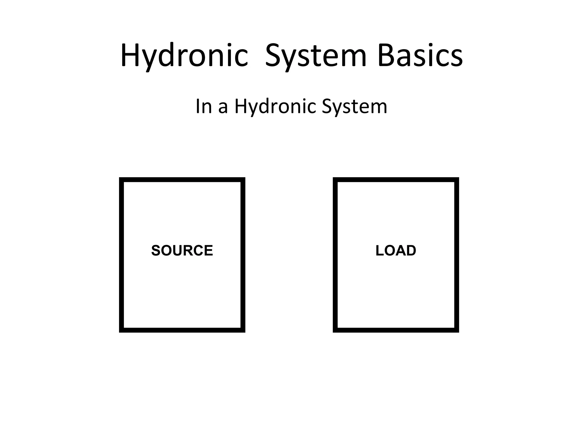
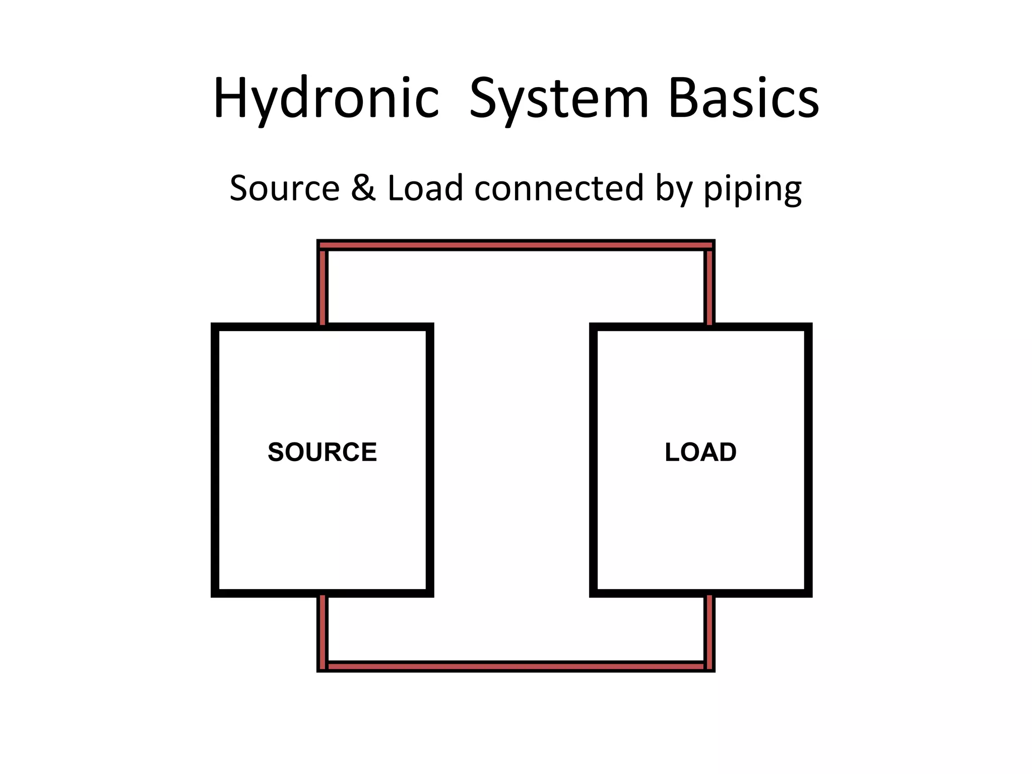
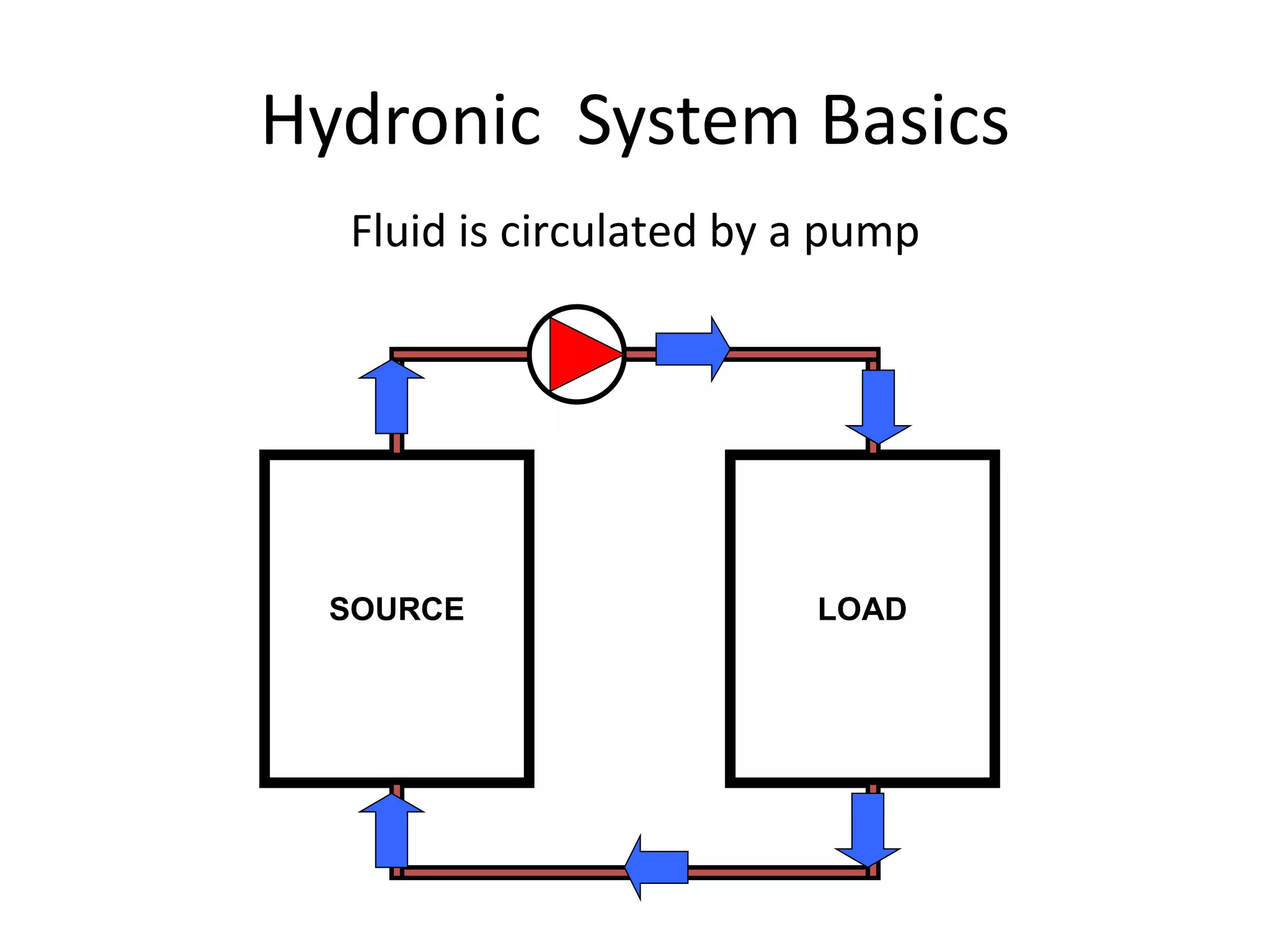

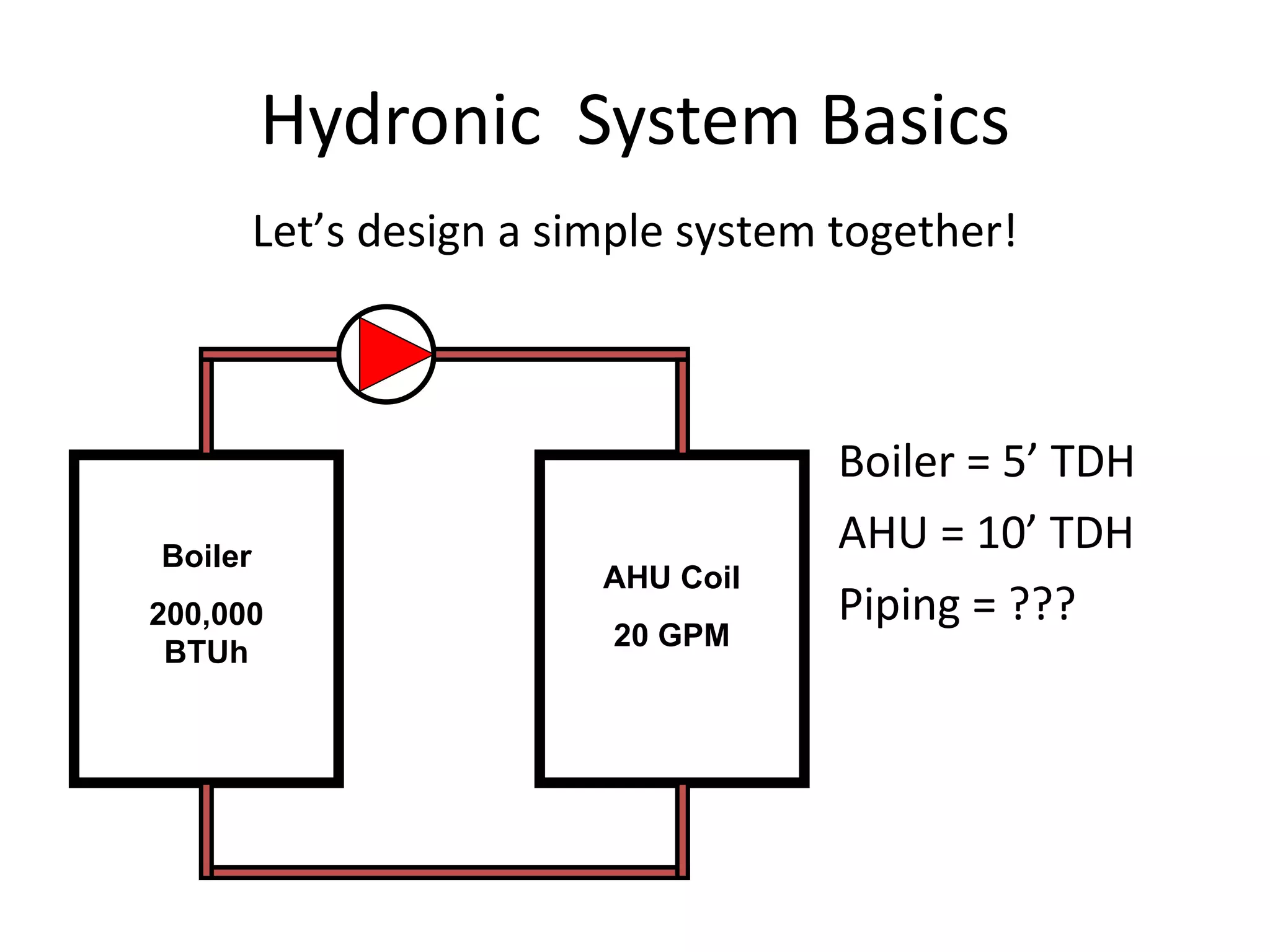
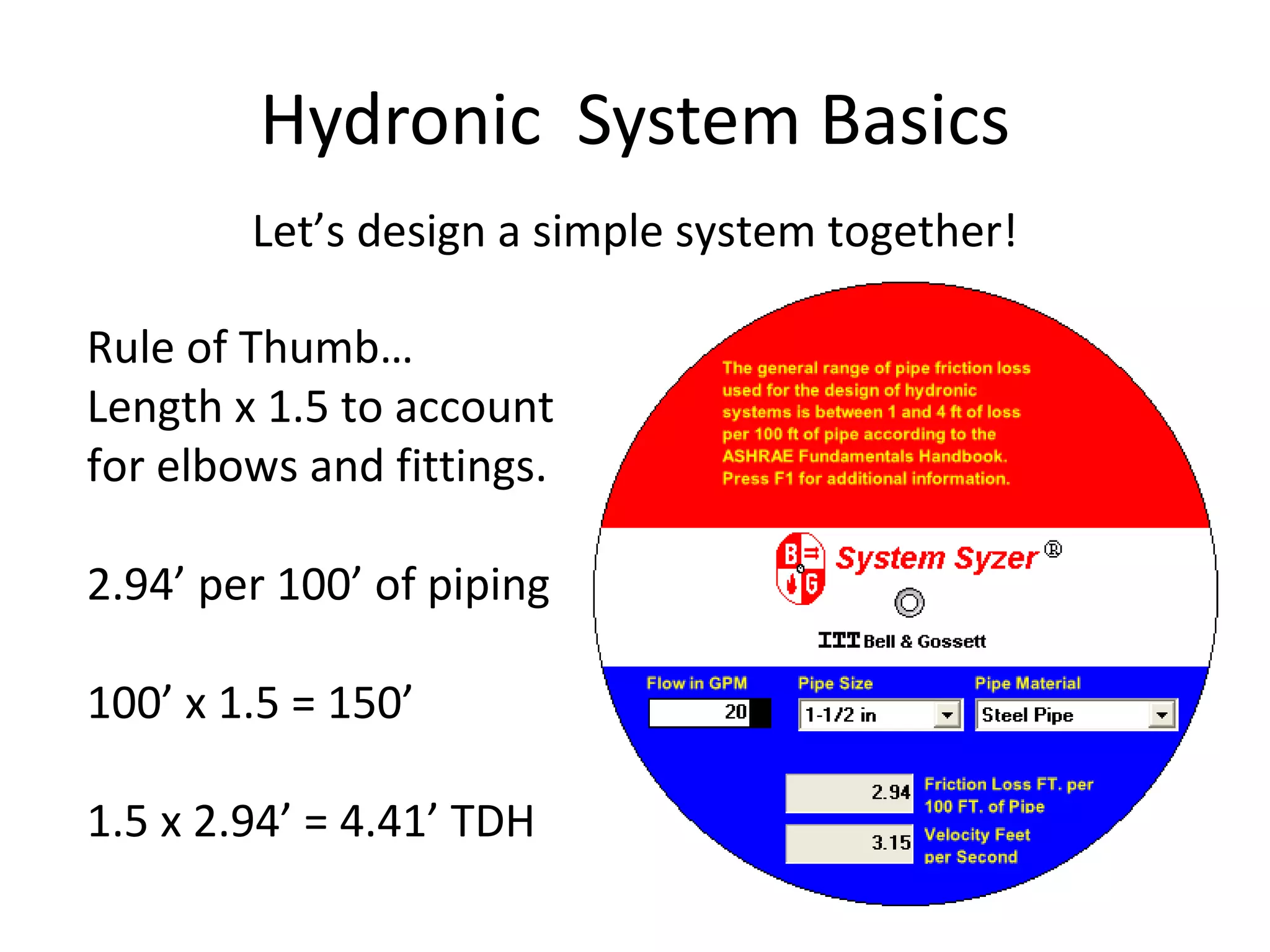


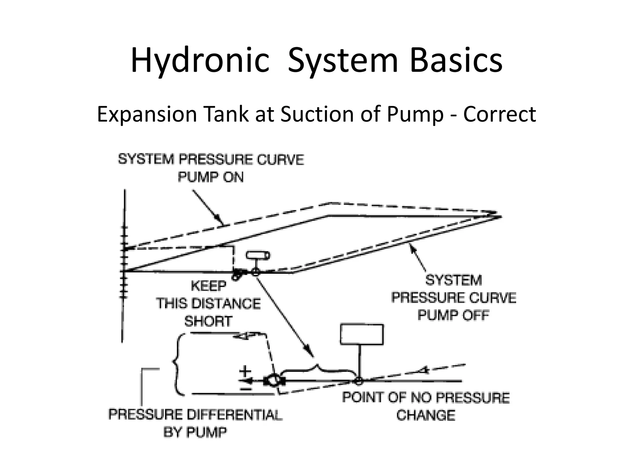

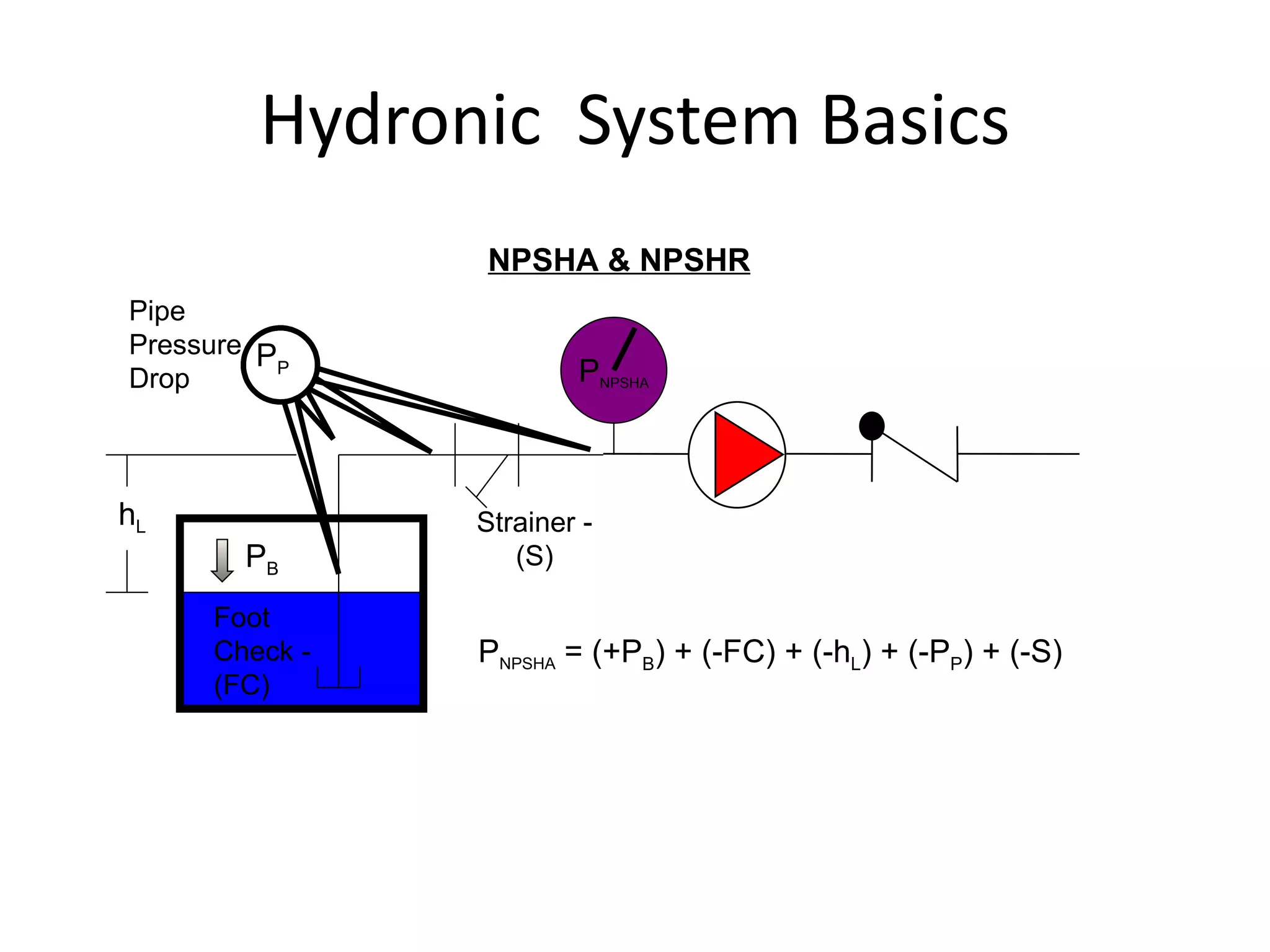
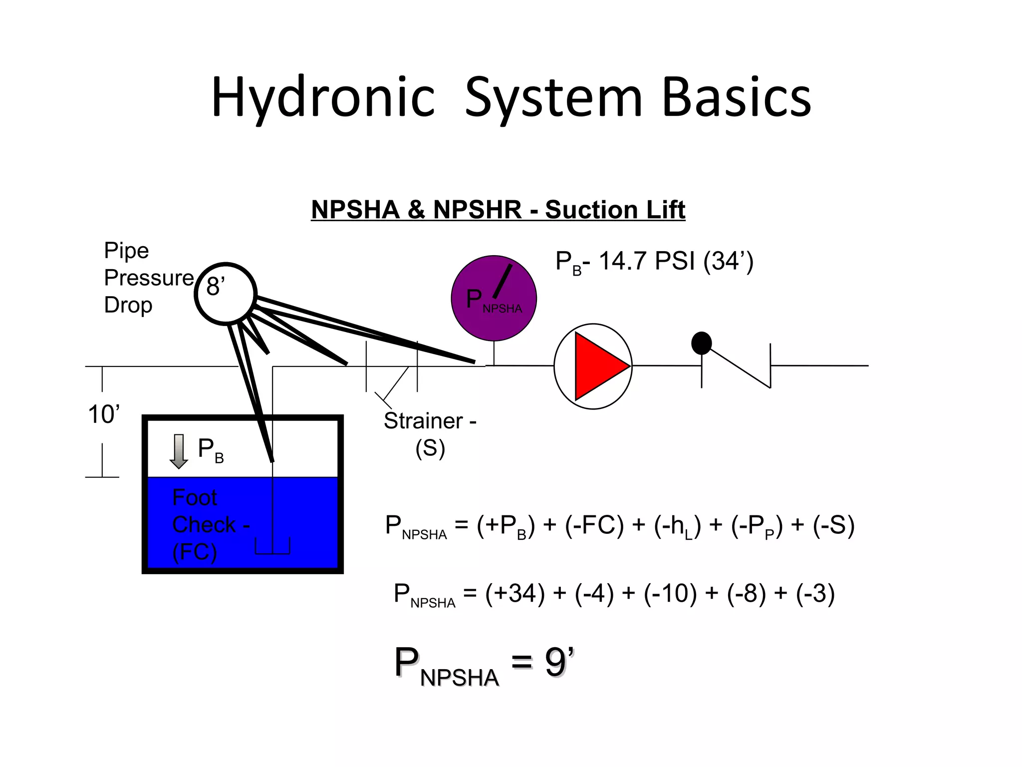


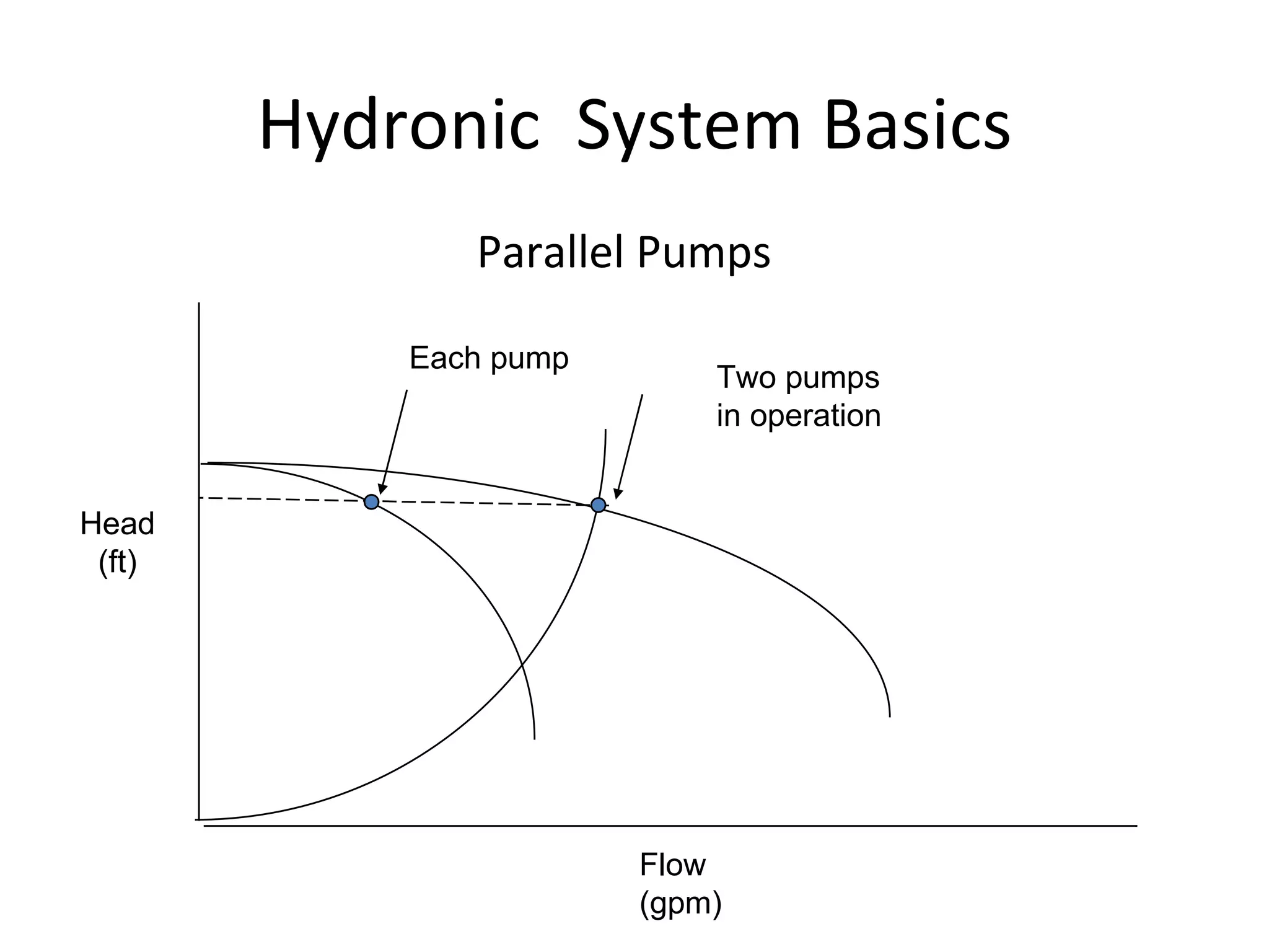


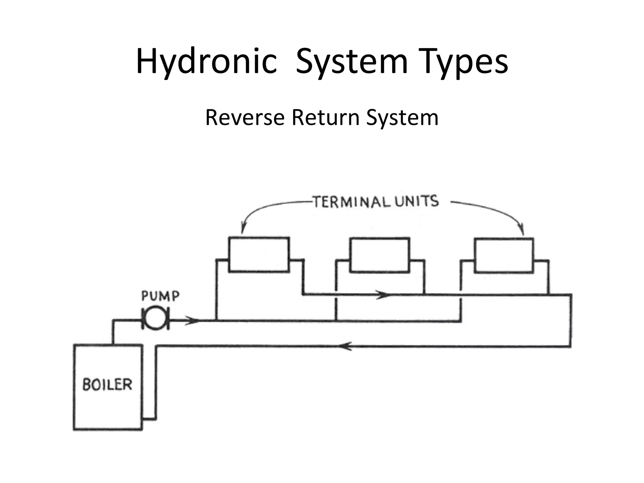
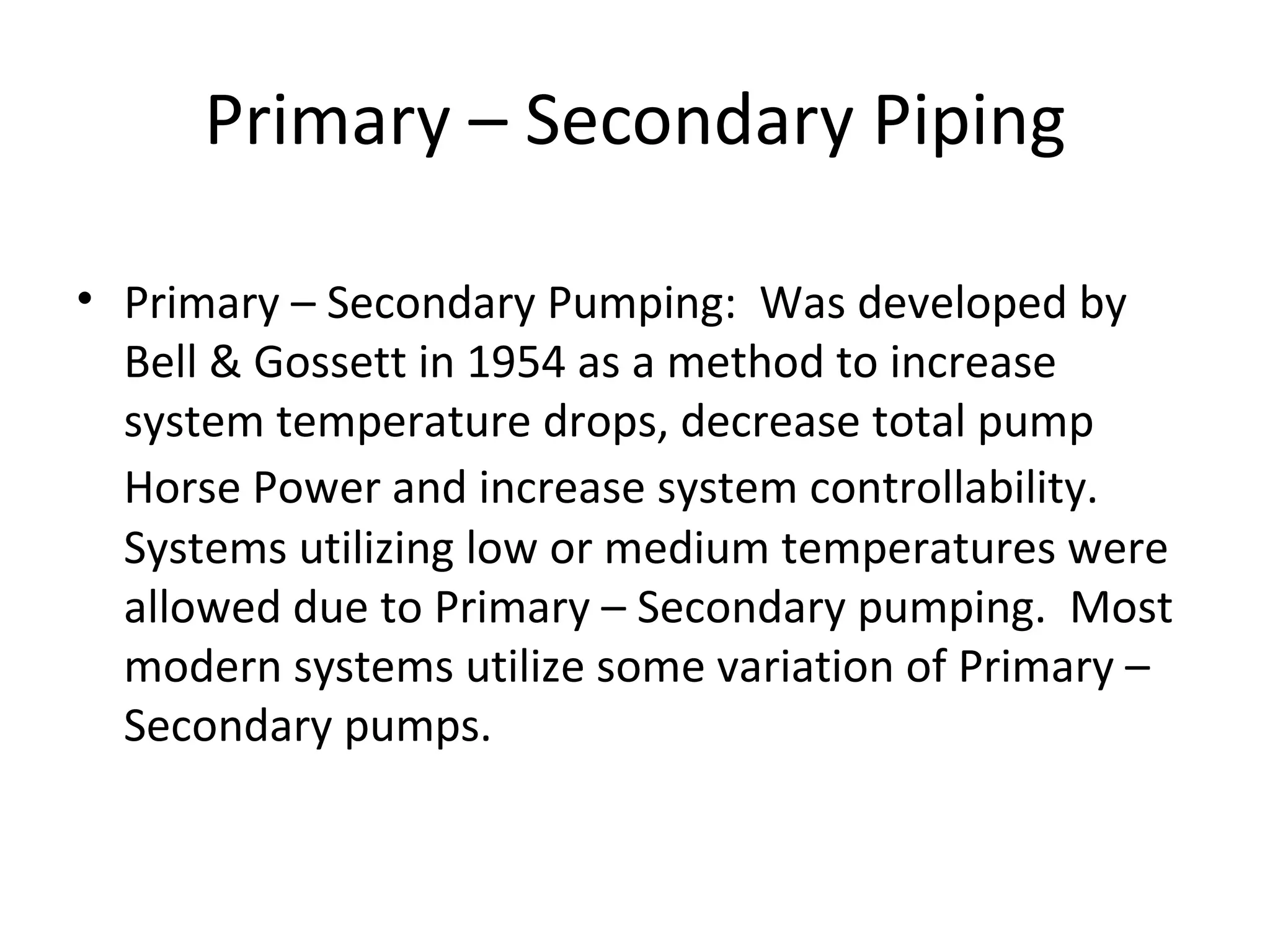


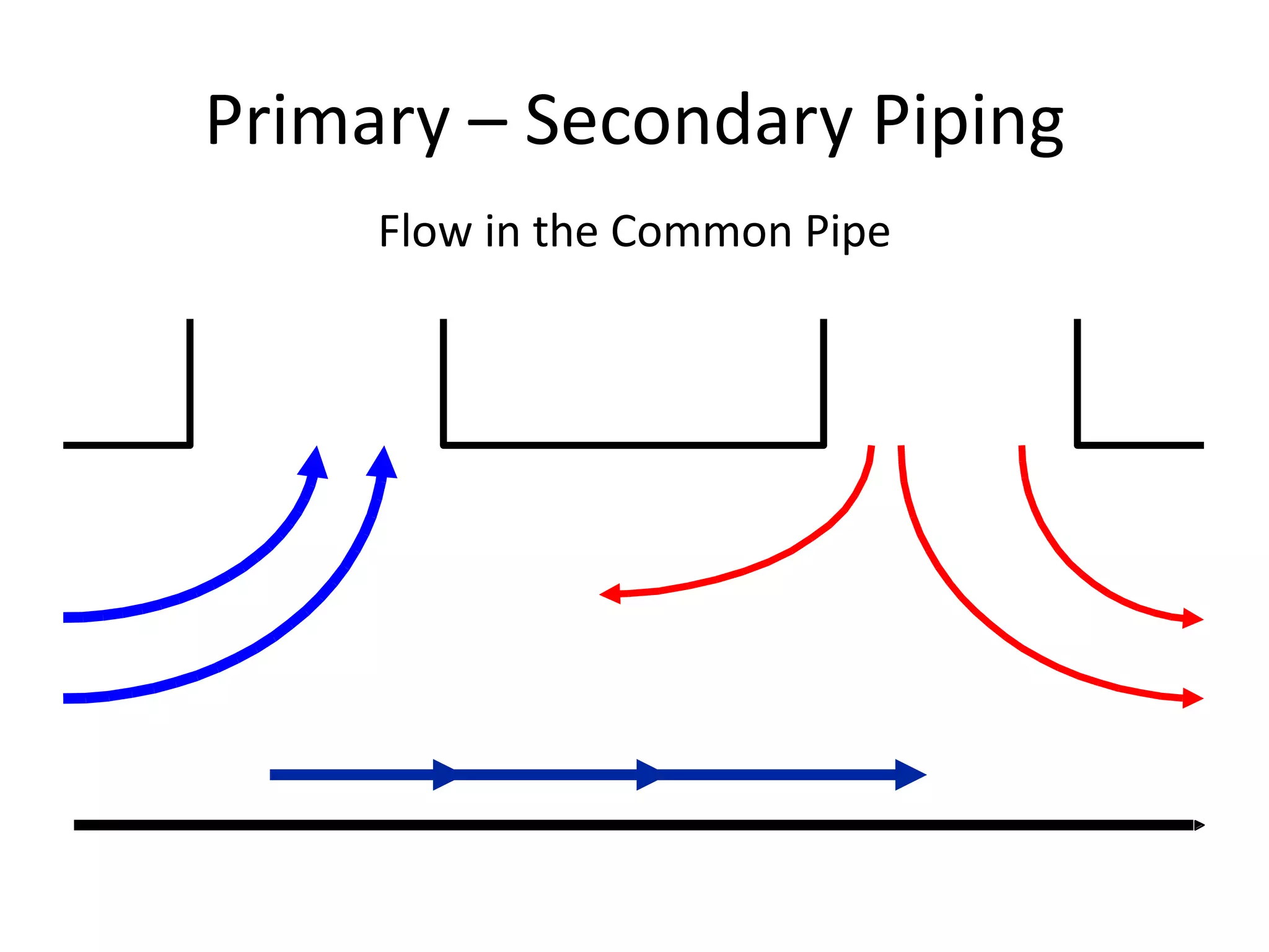


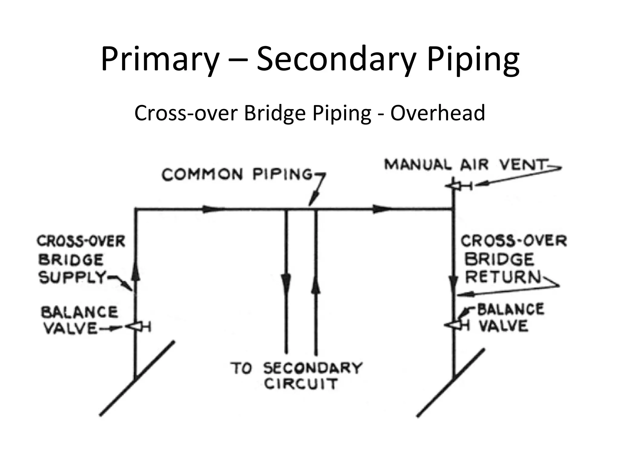


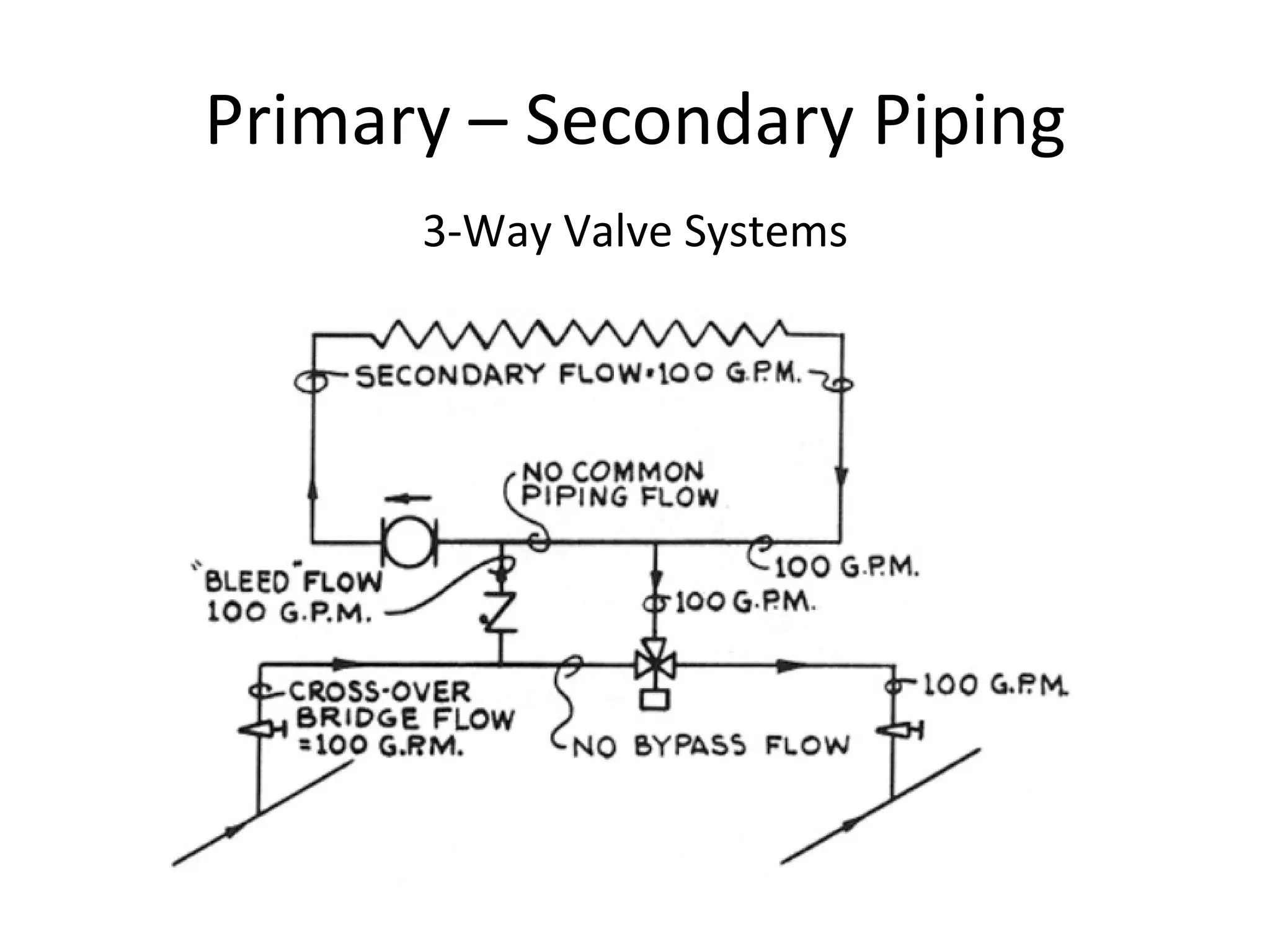
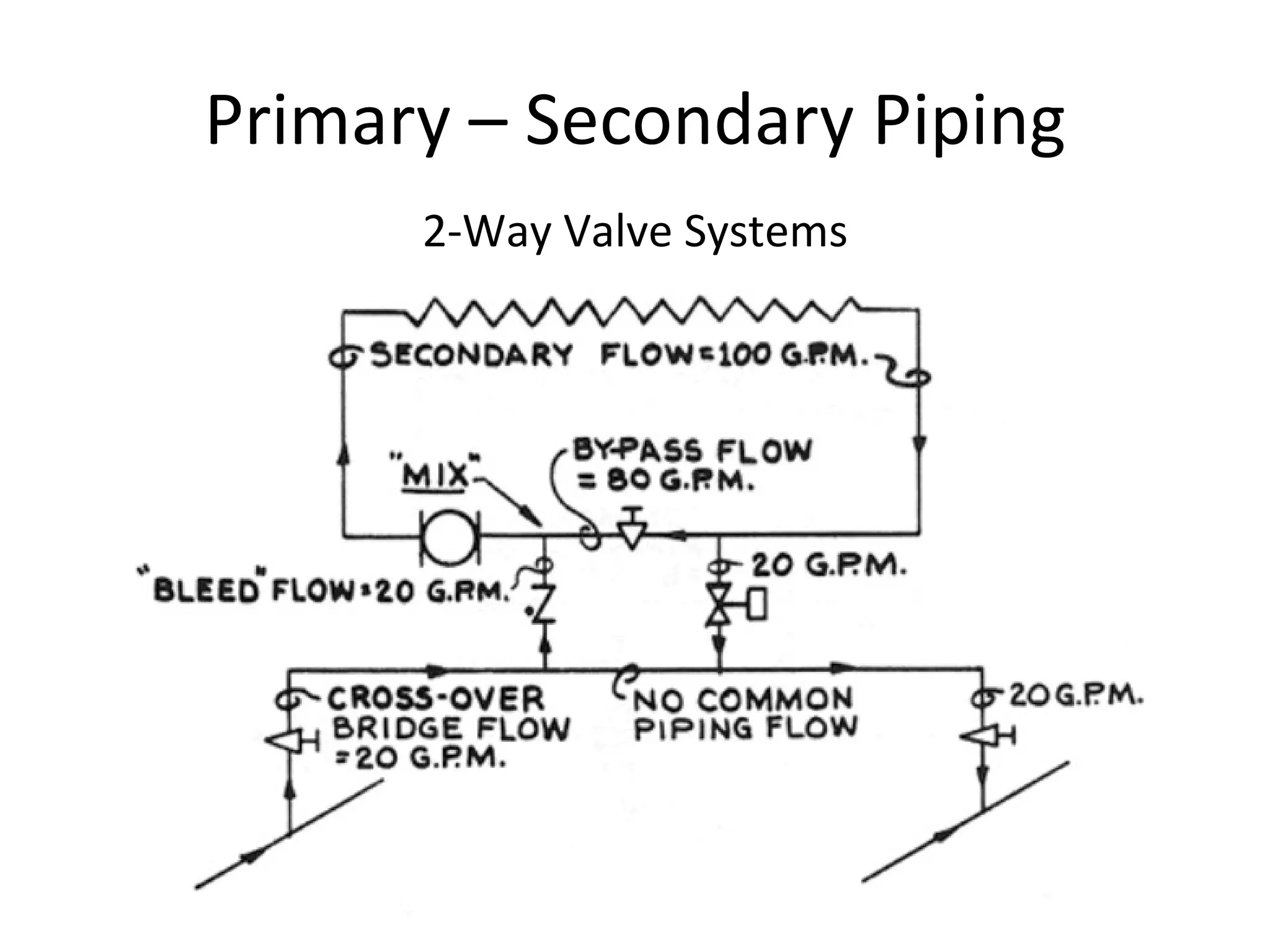
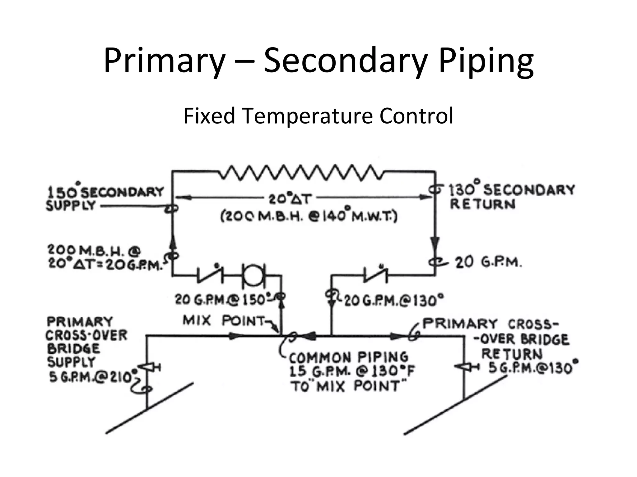


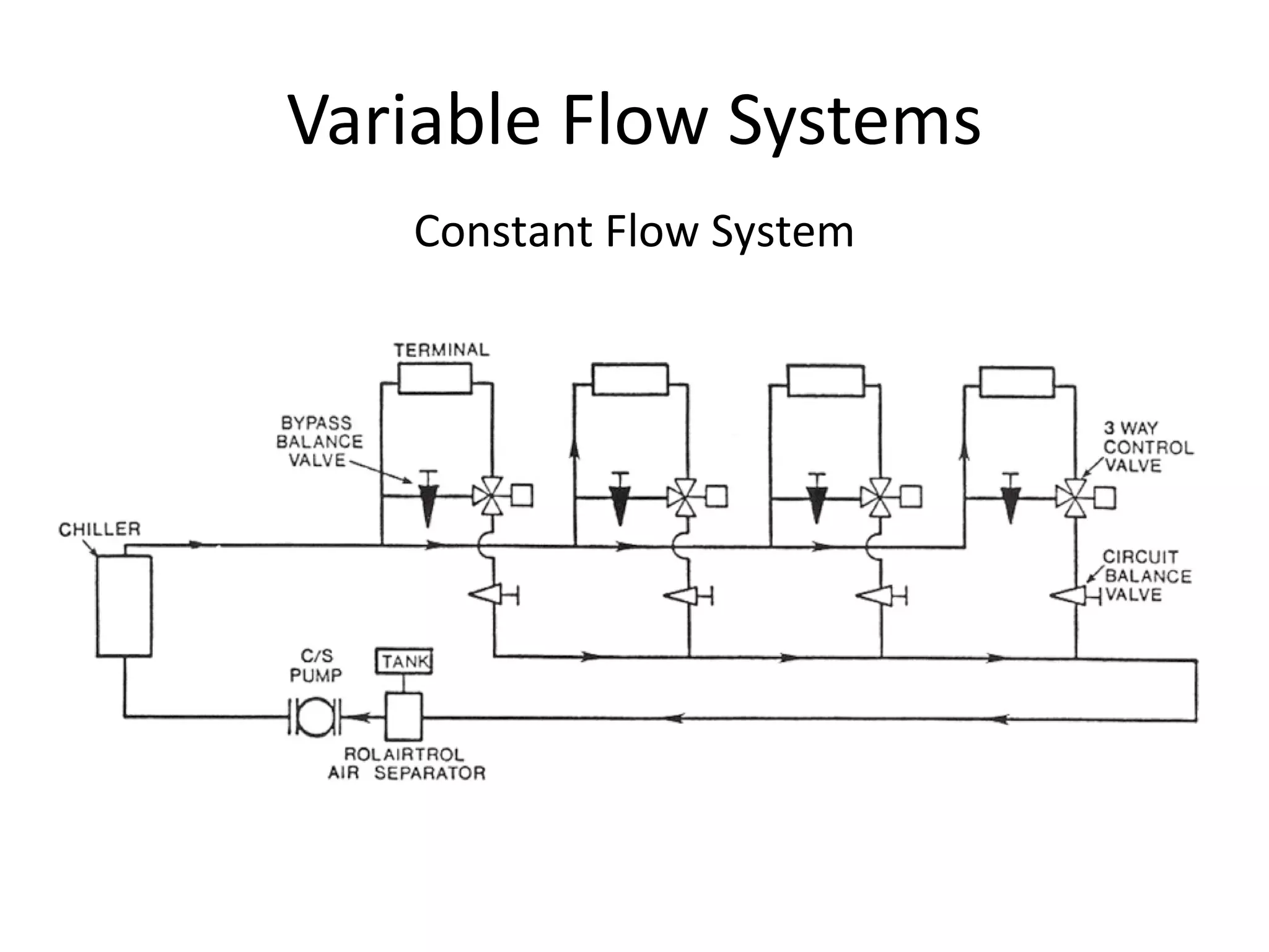


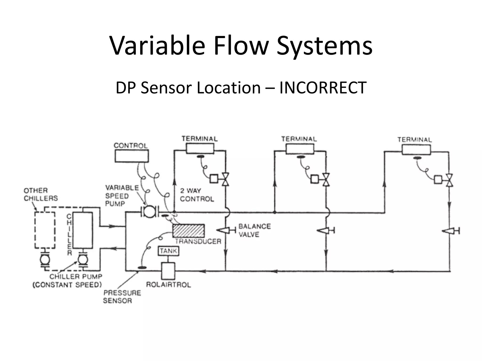


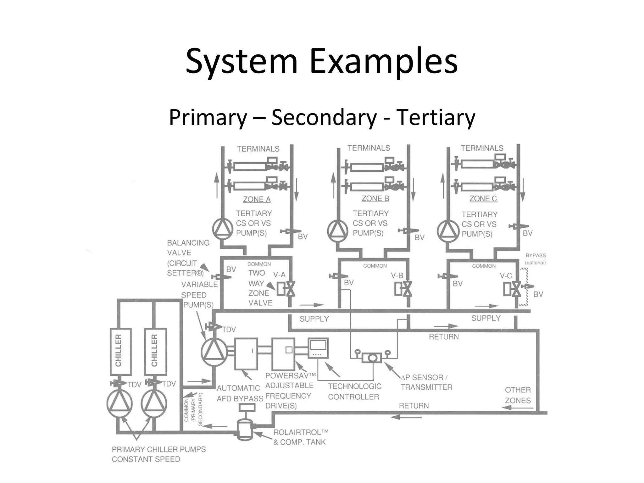
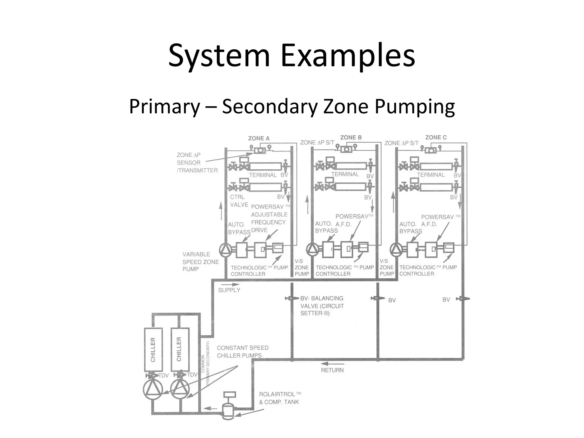
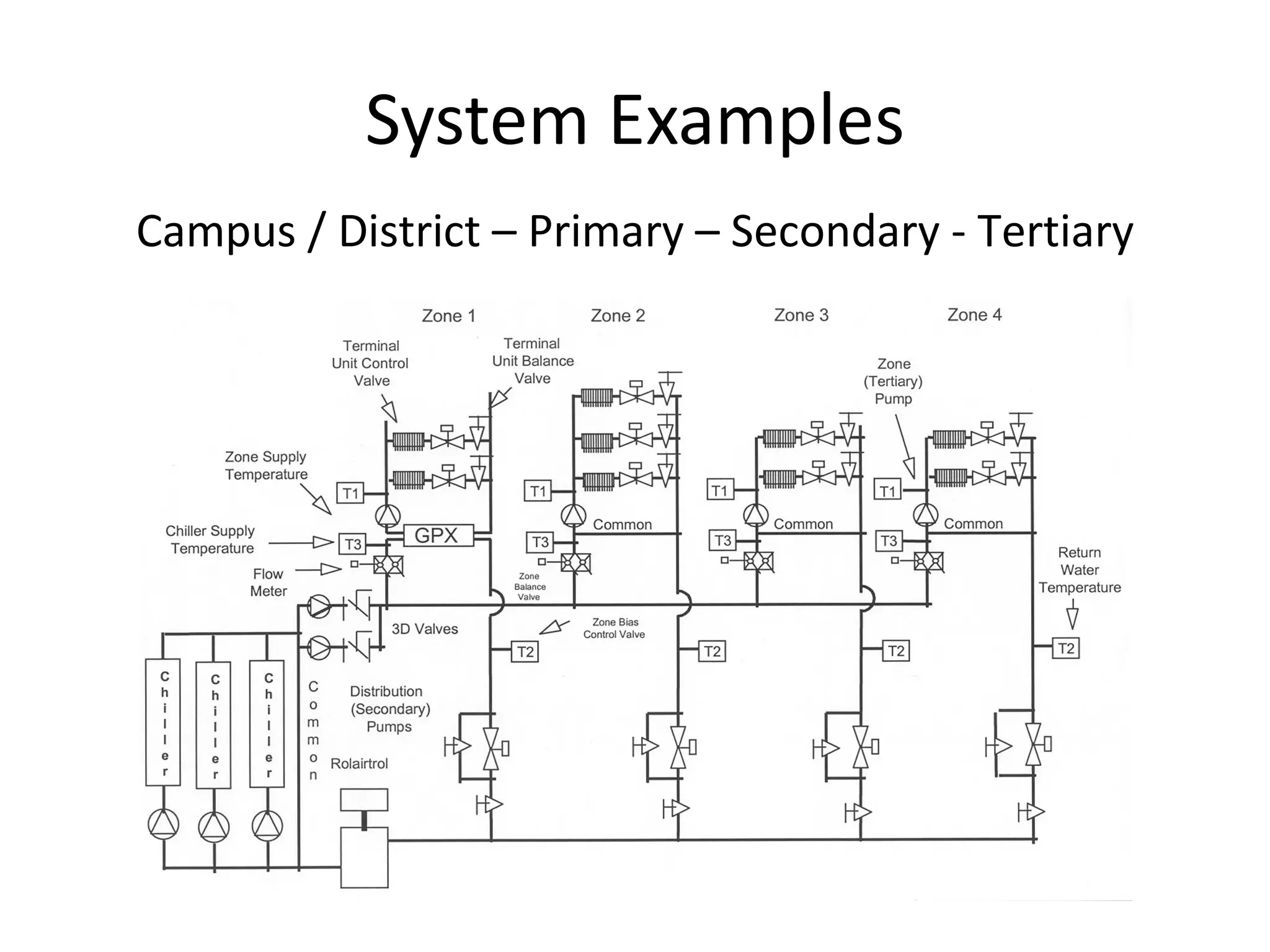


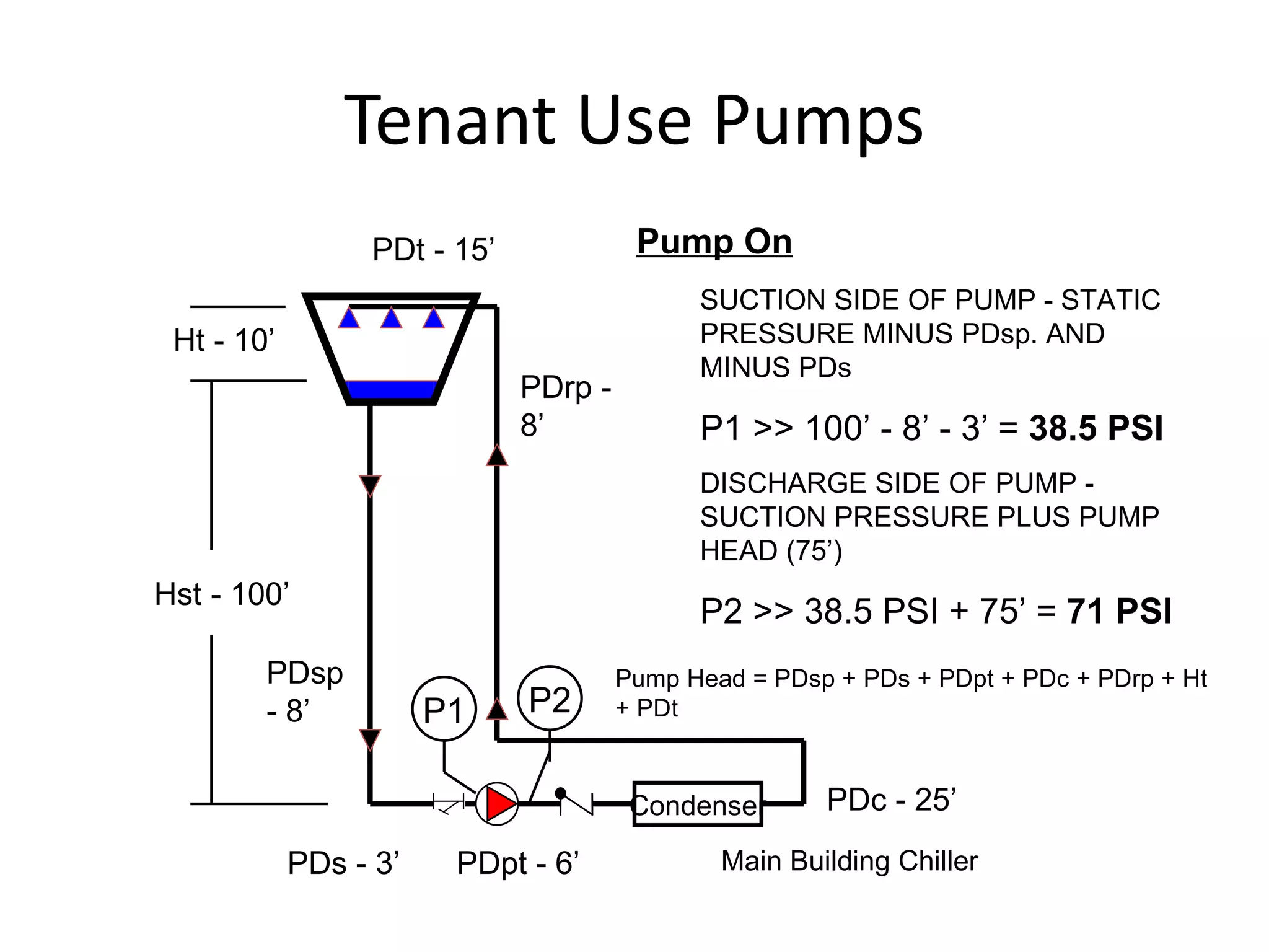


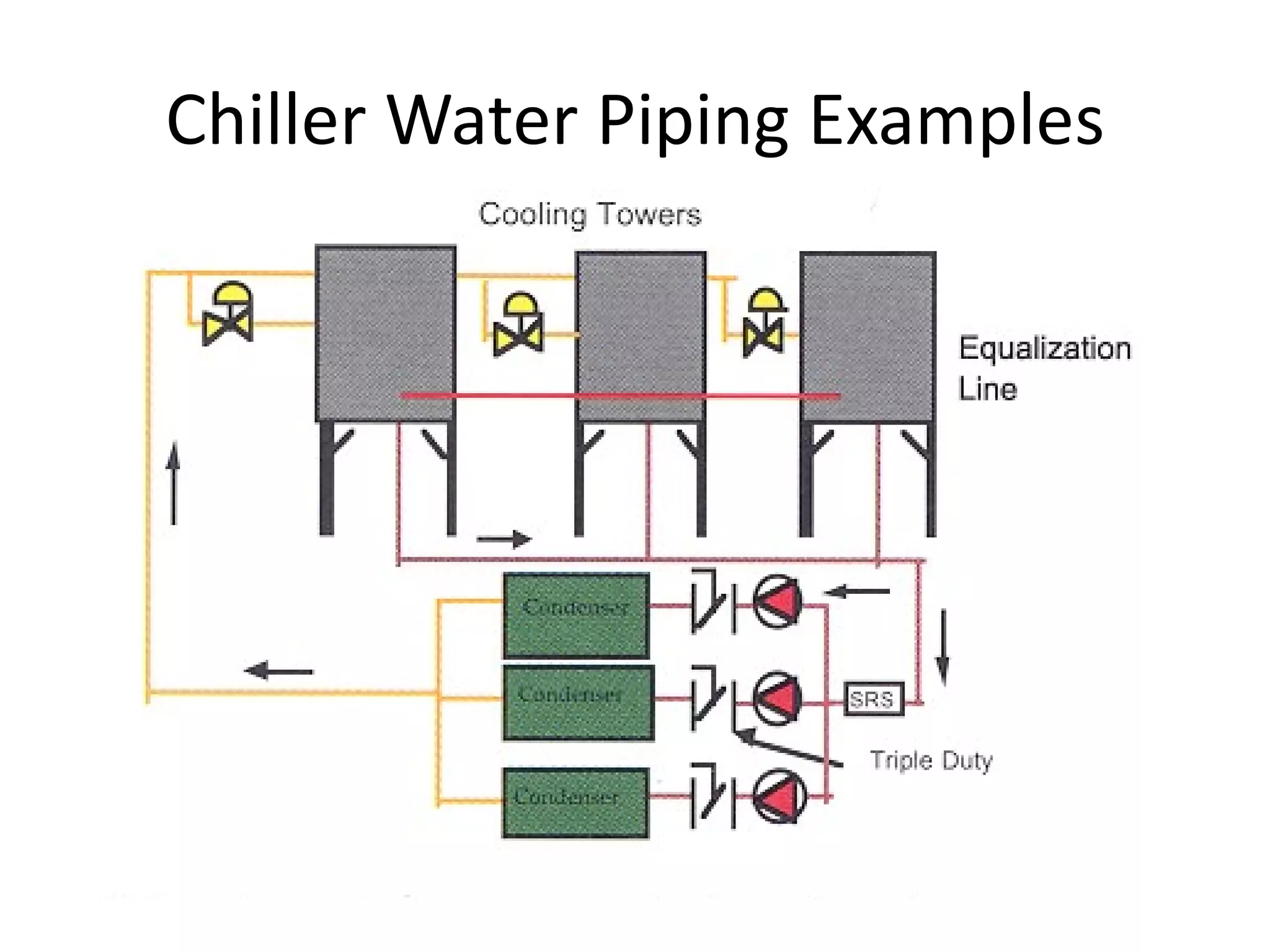
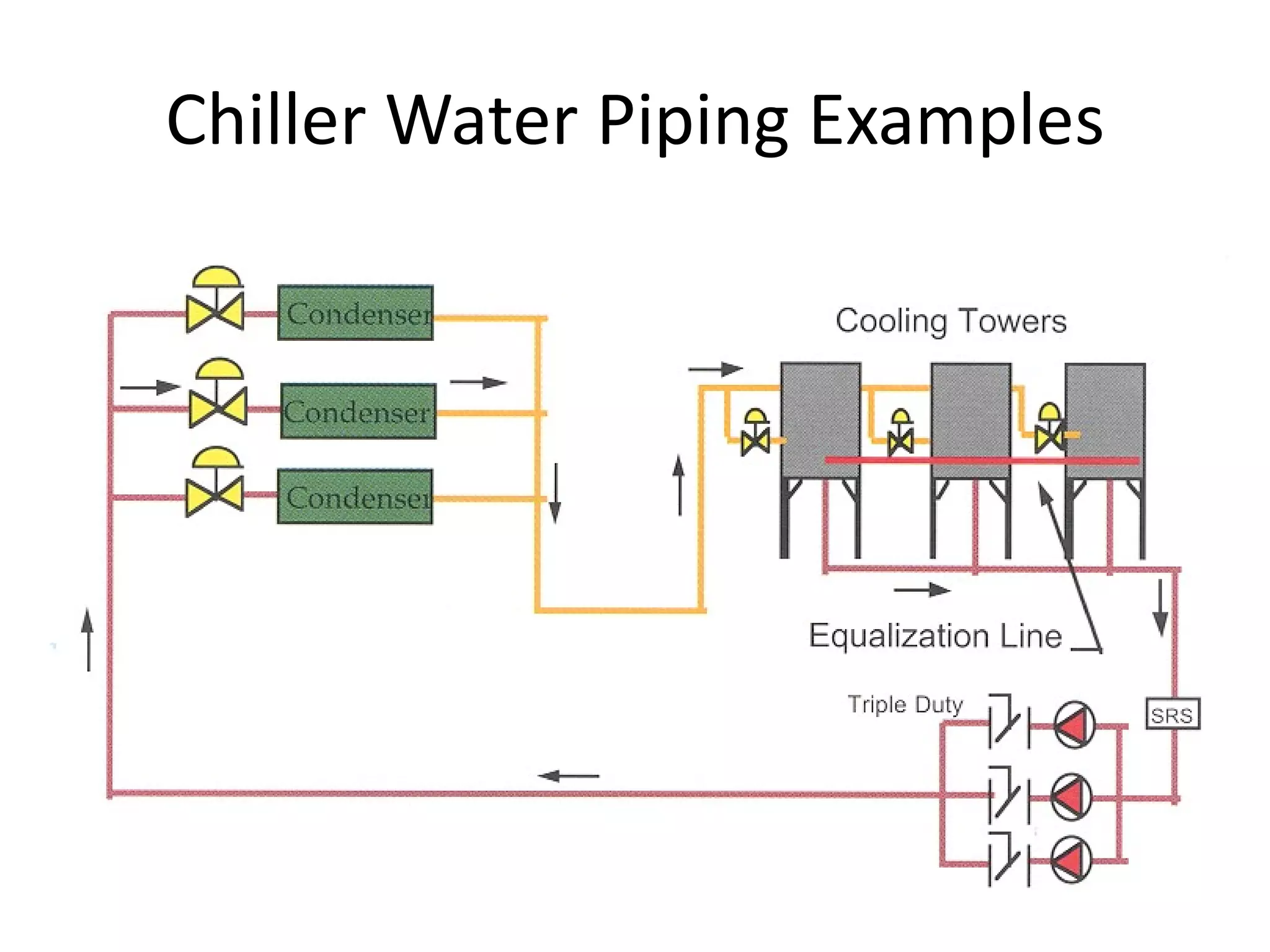
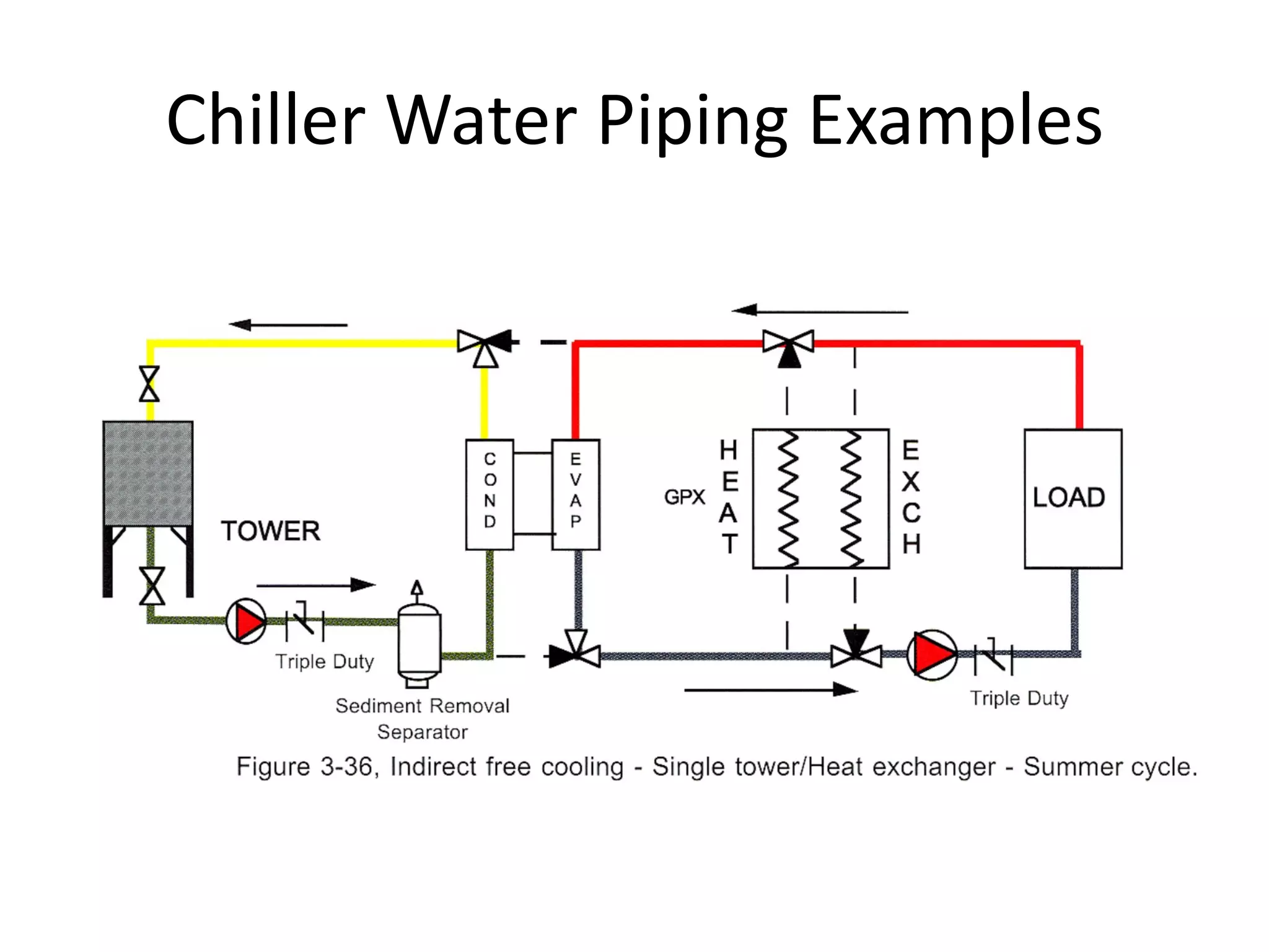
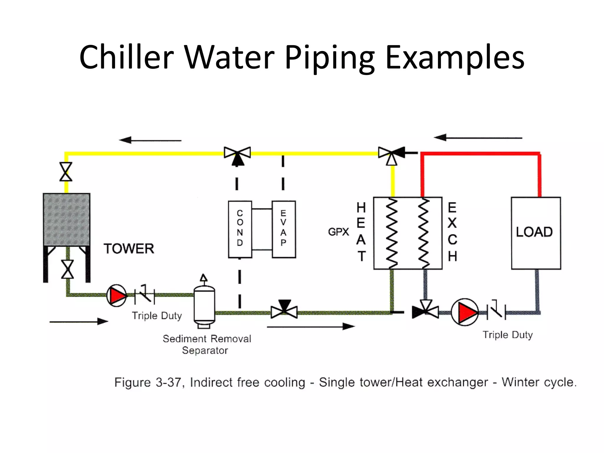
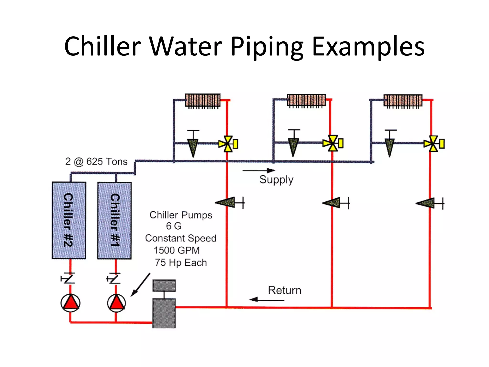


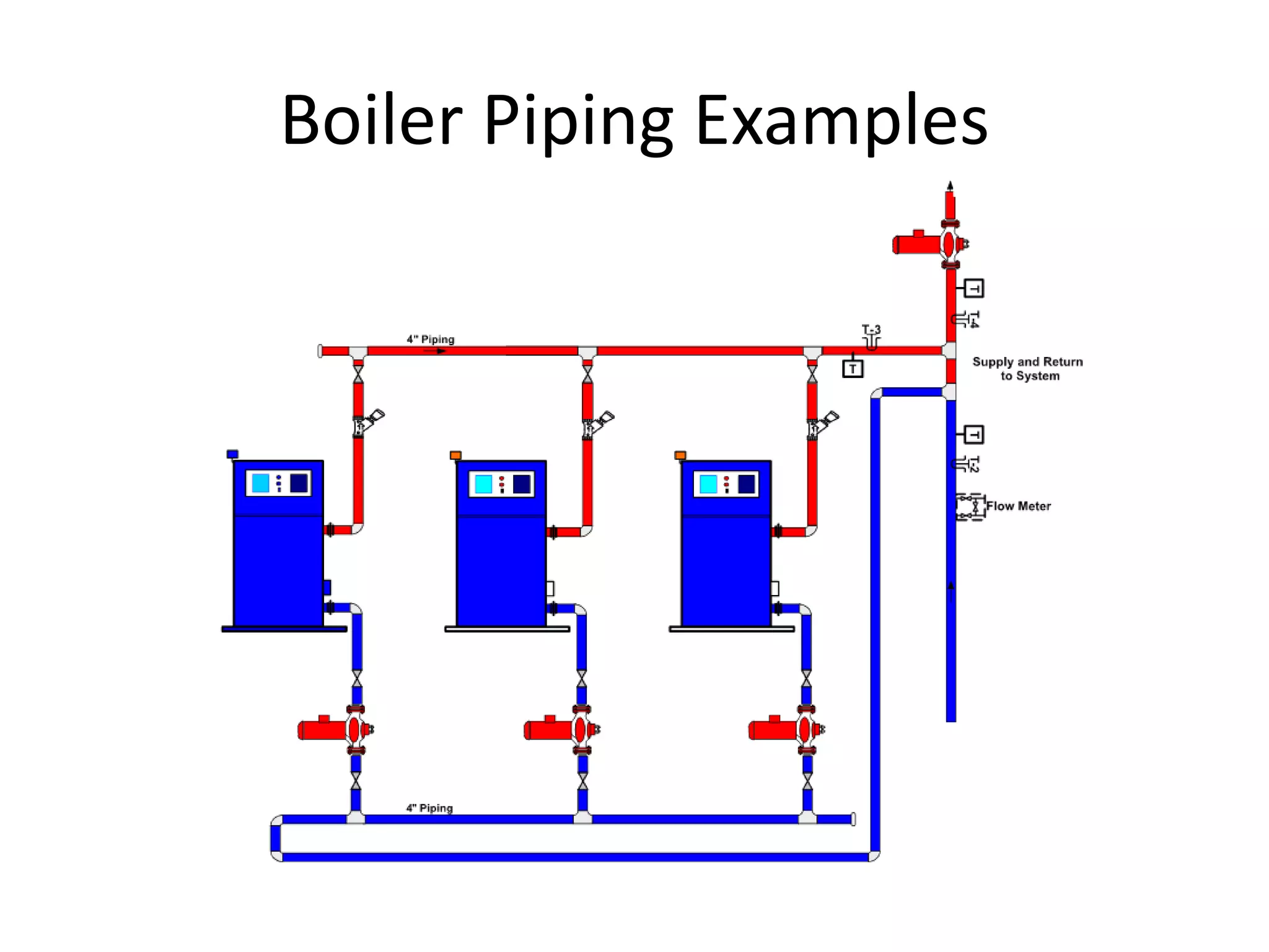
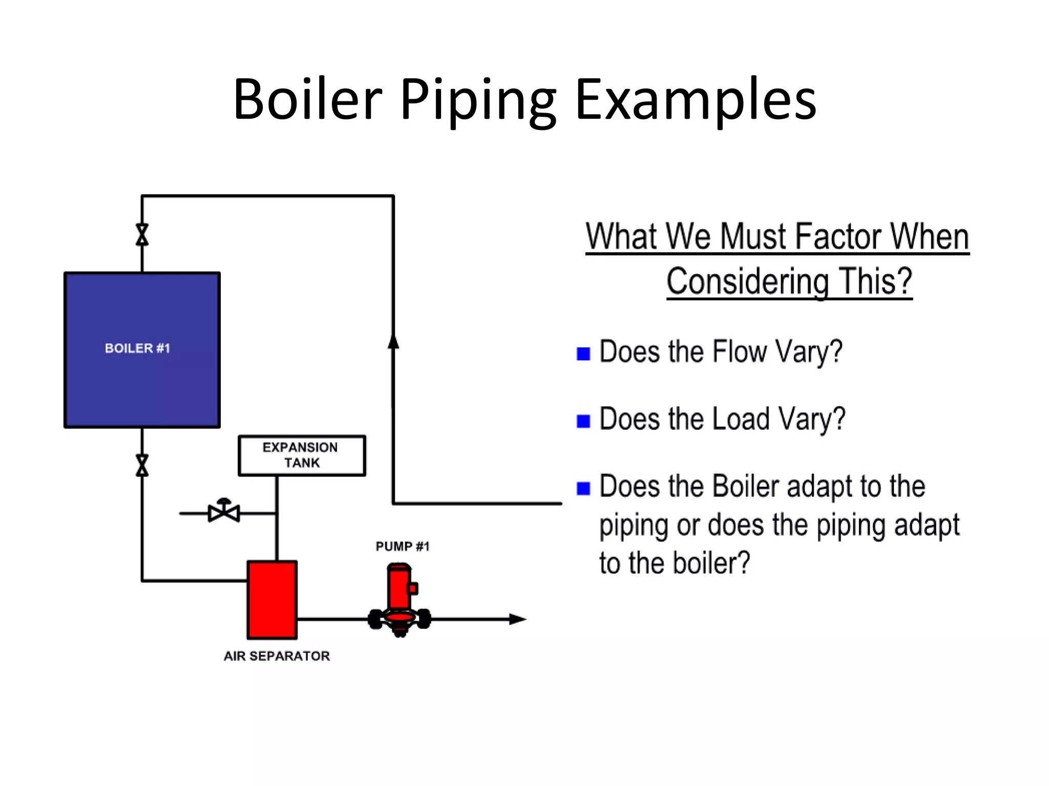
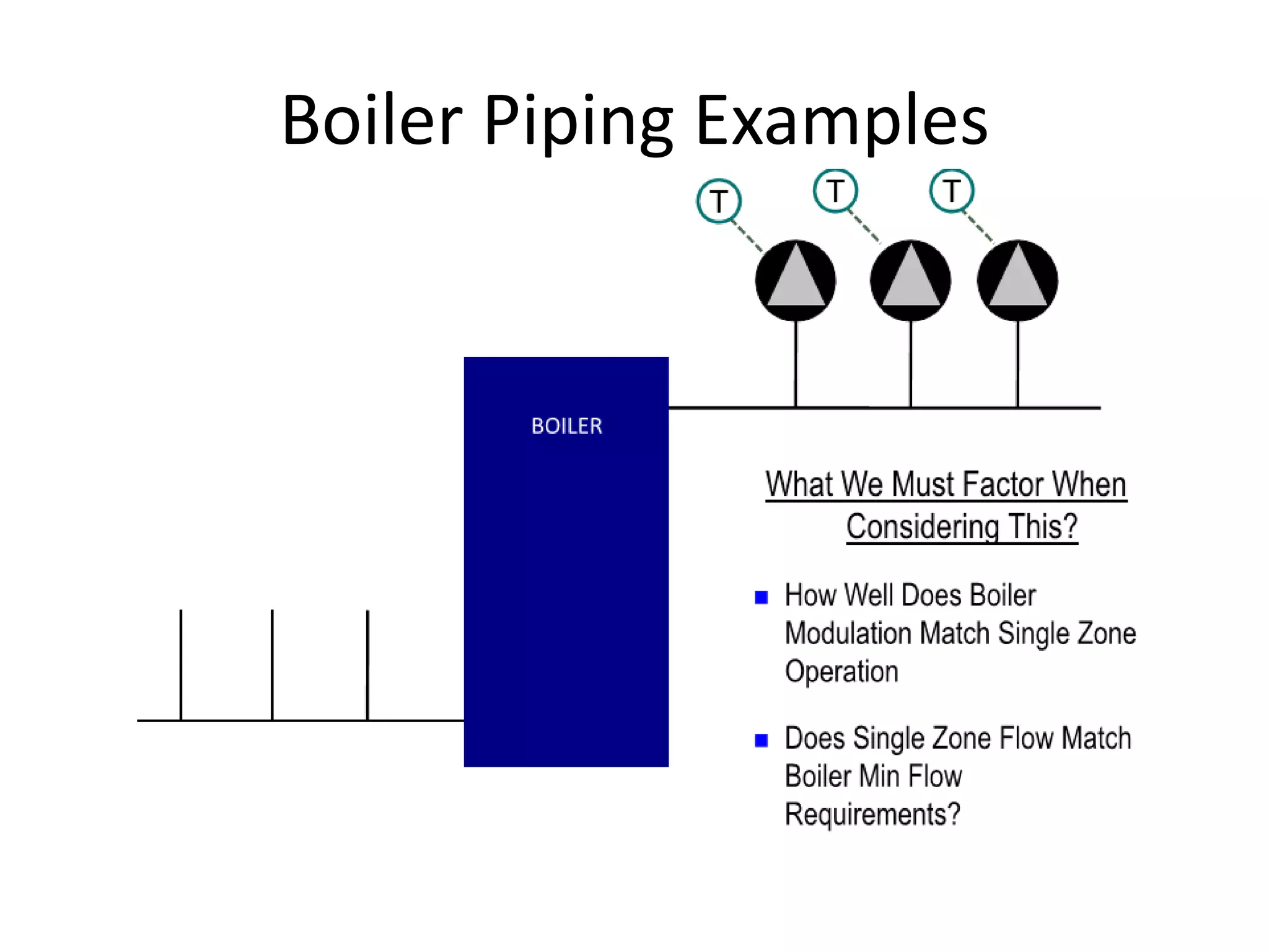


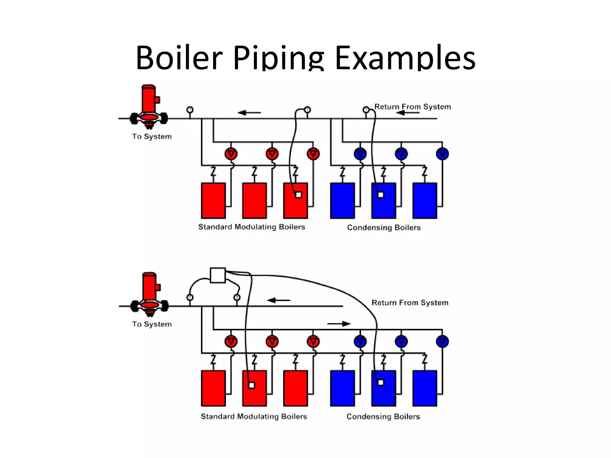

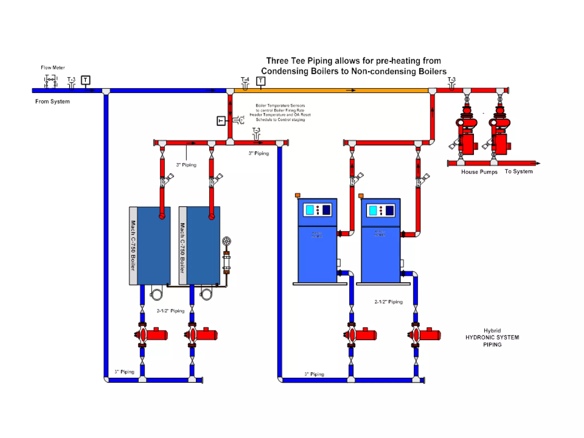
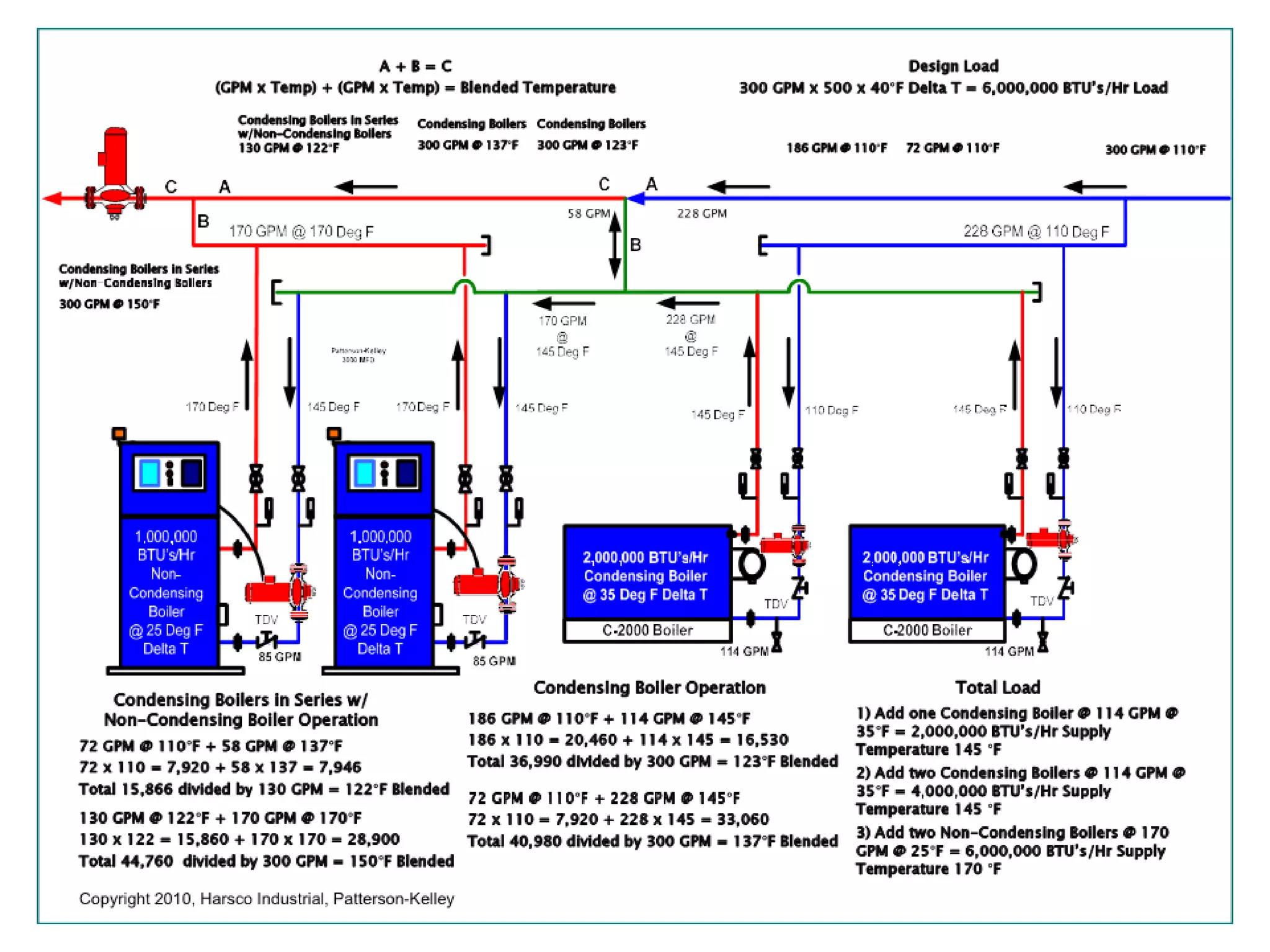
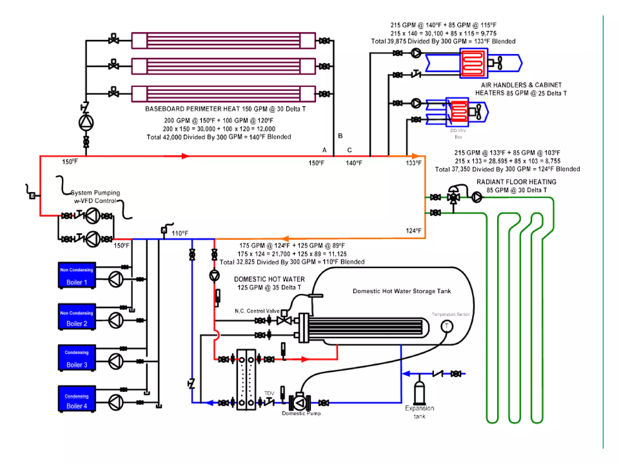


The document discusses various topics related to hydronic system design including: - Common hydronic system types like primary-secondary and variable flow systems - Key considerations for piping design like pump sizing, pressure drops, and expansion tank placement - Examples of specific system designs for chilled water, boiler water, and complex multi-building systems - Benefits of variable speed pumps for energy efficiency and system controllability


