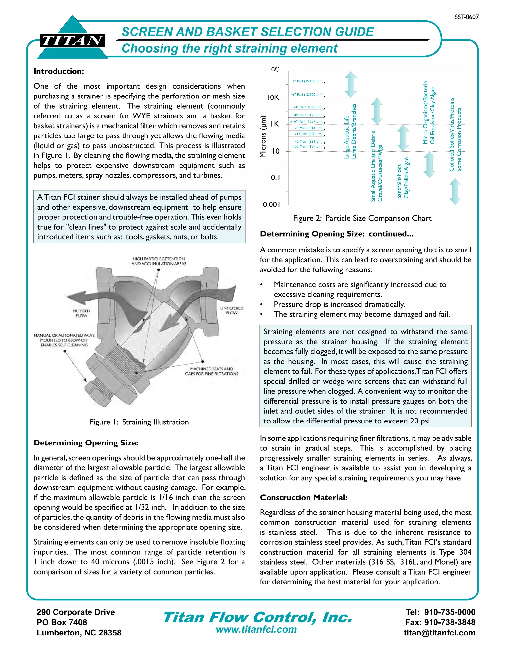
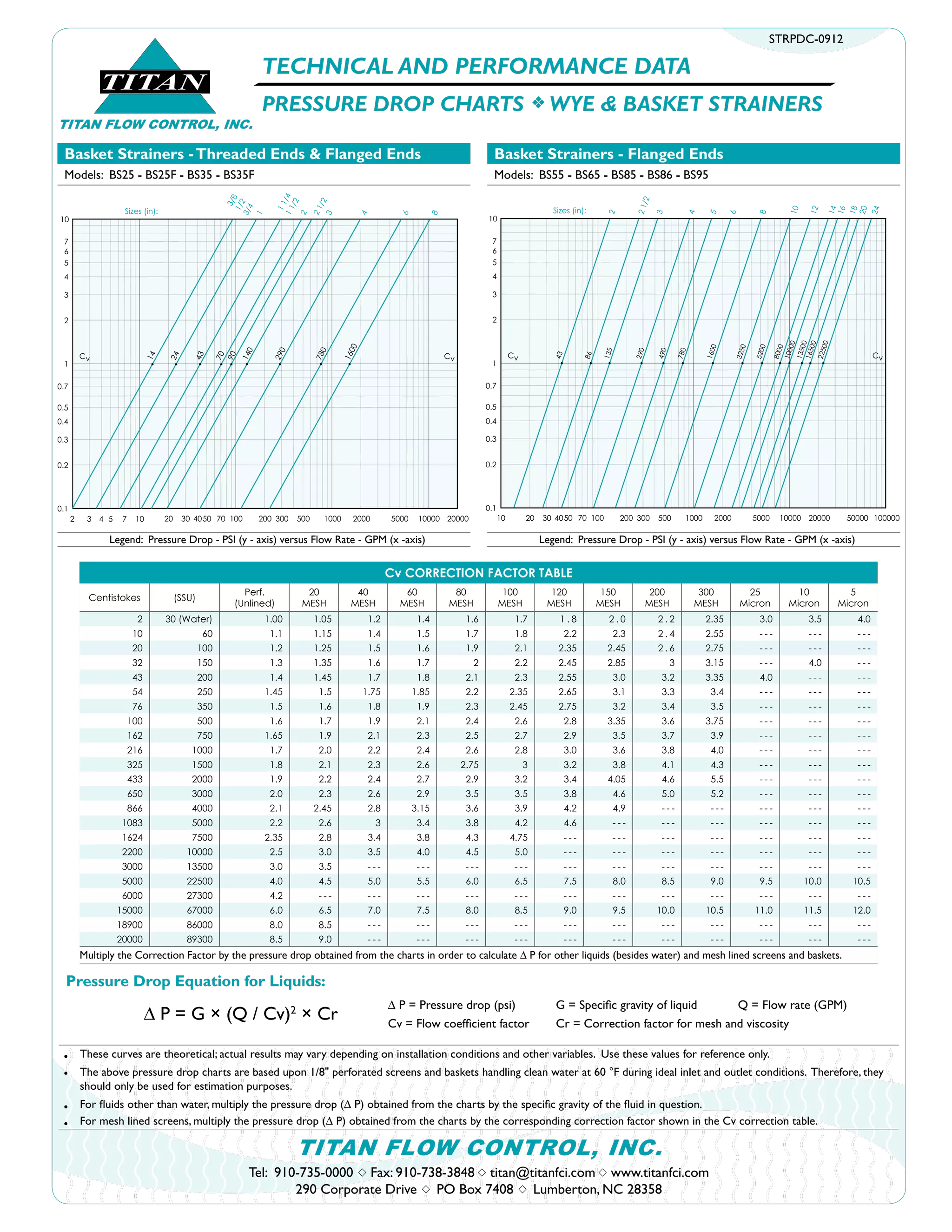
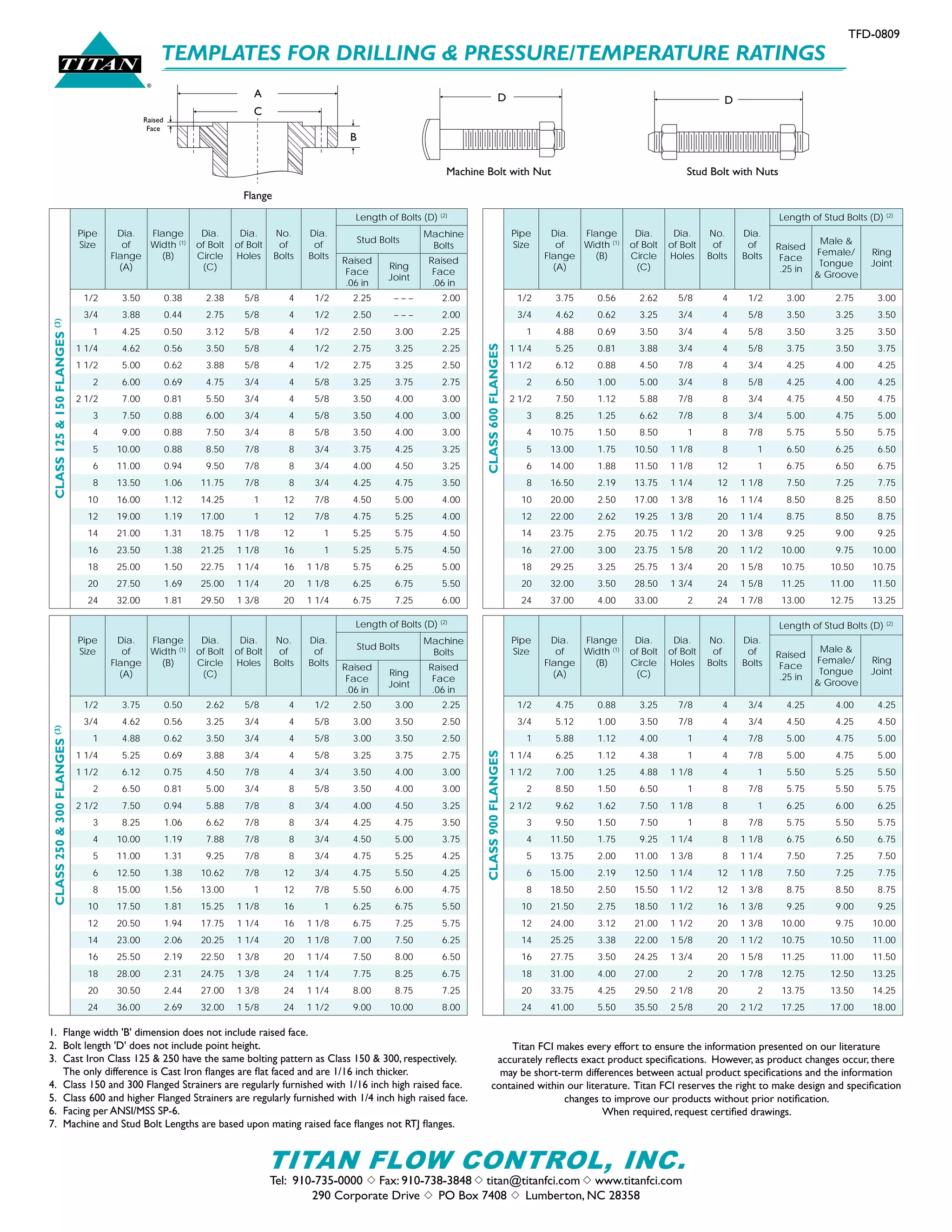
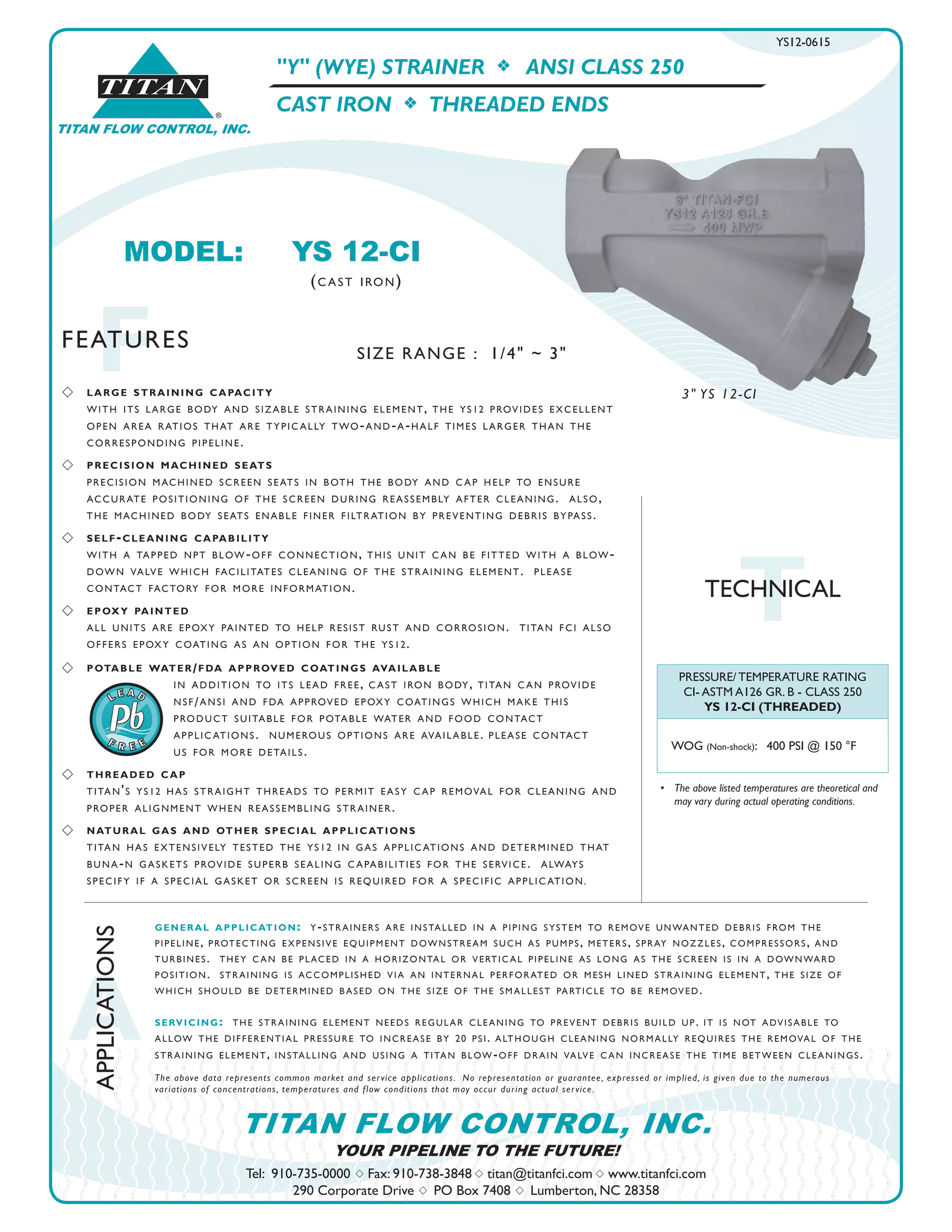
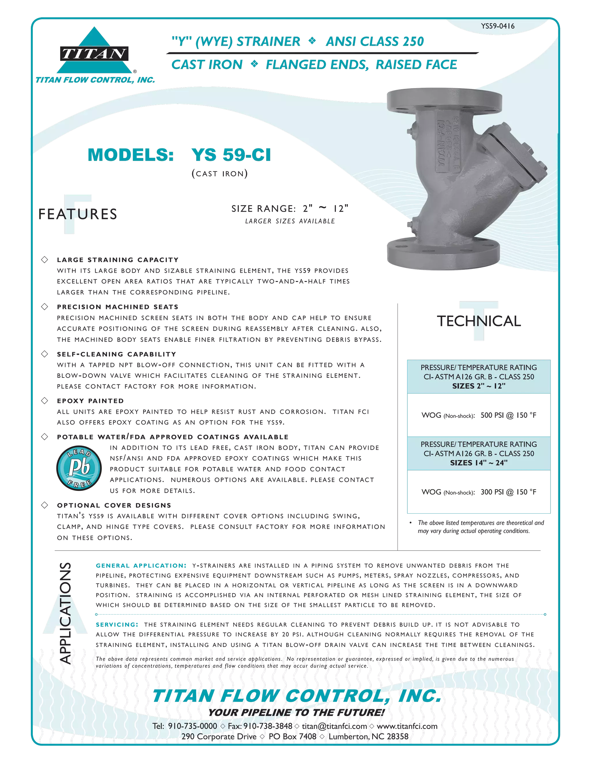
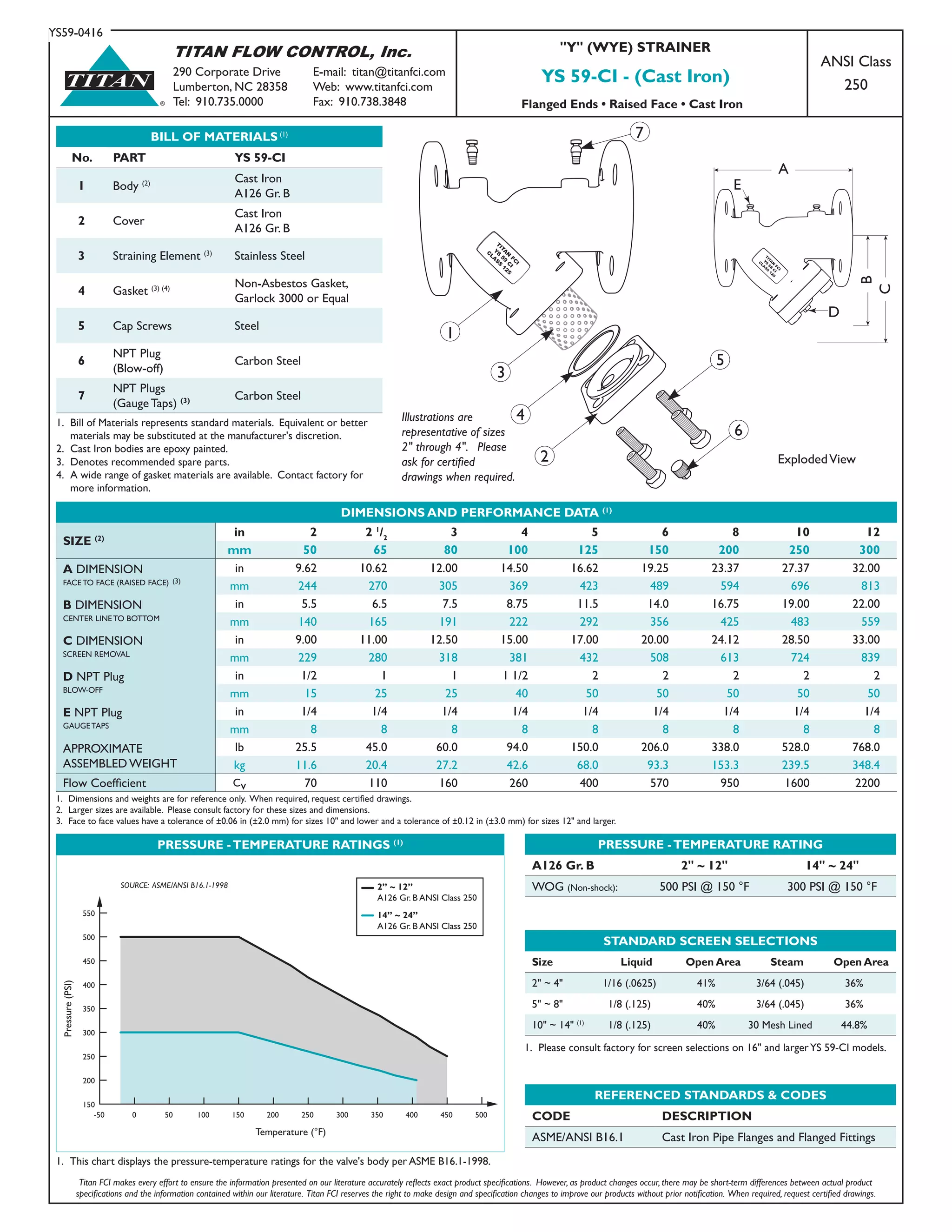
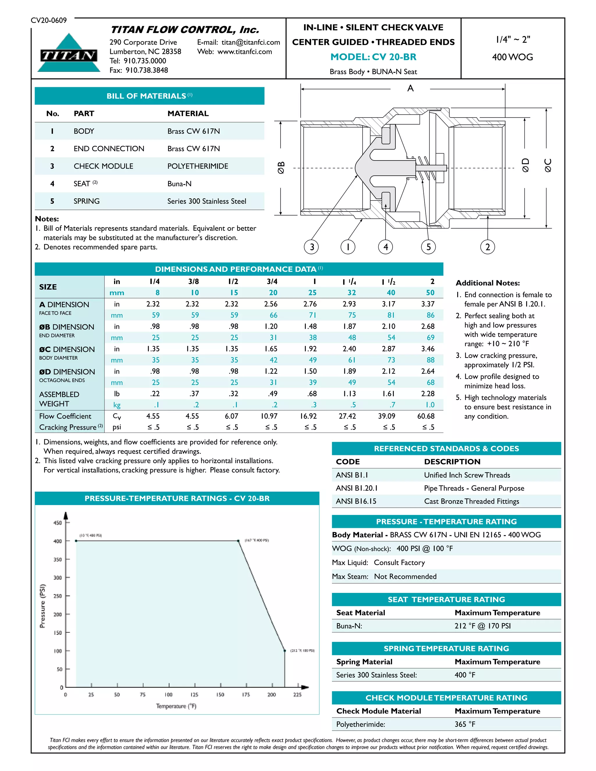
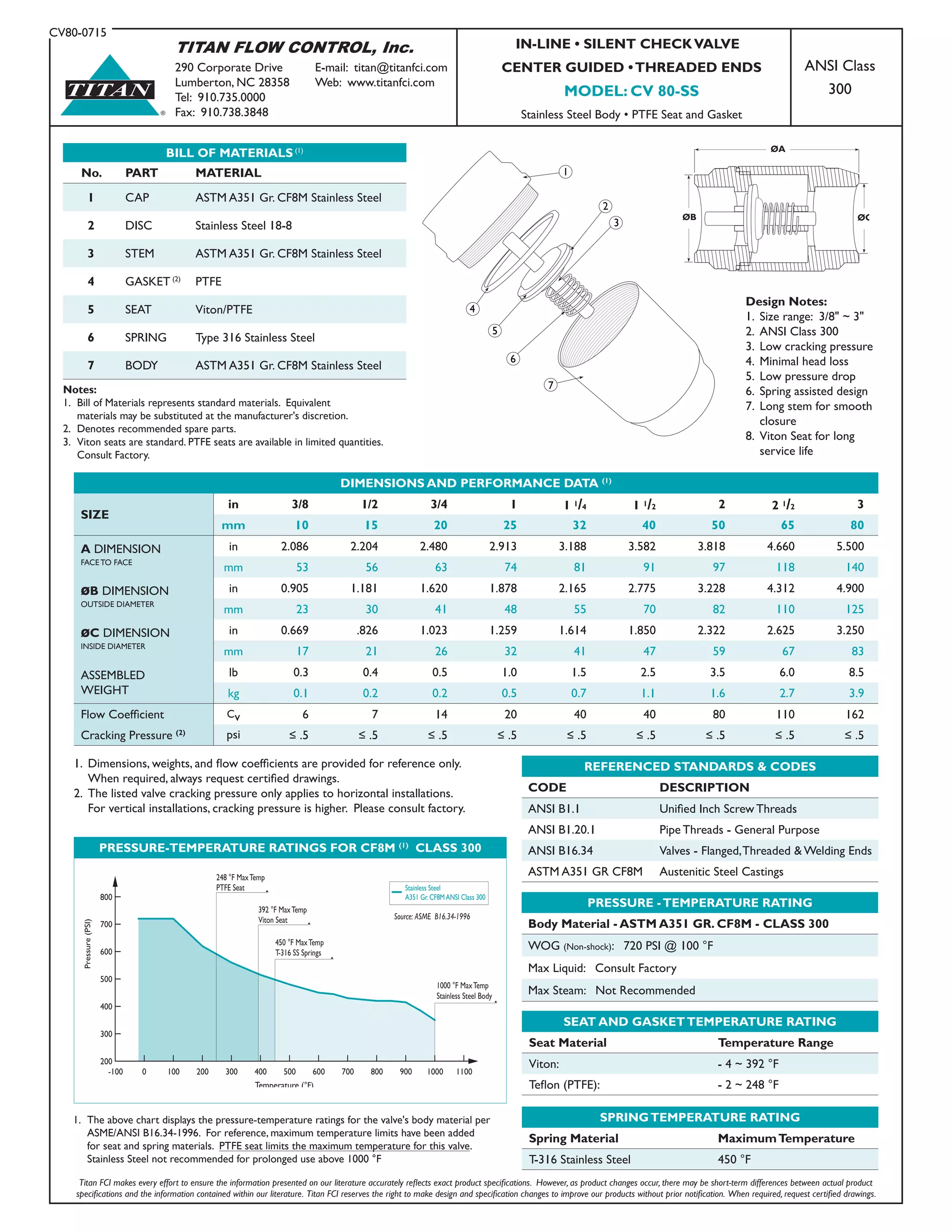
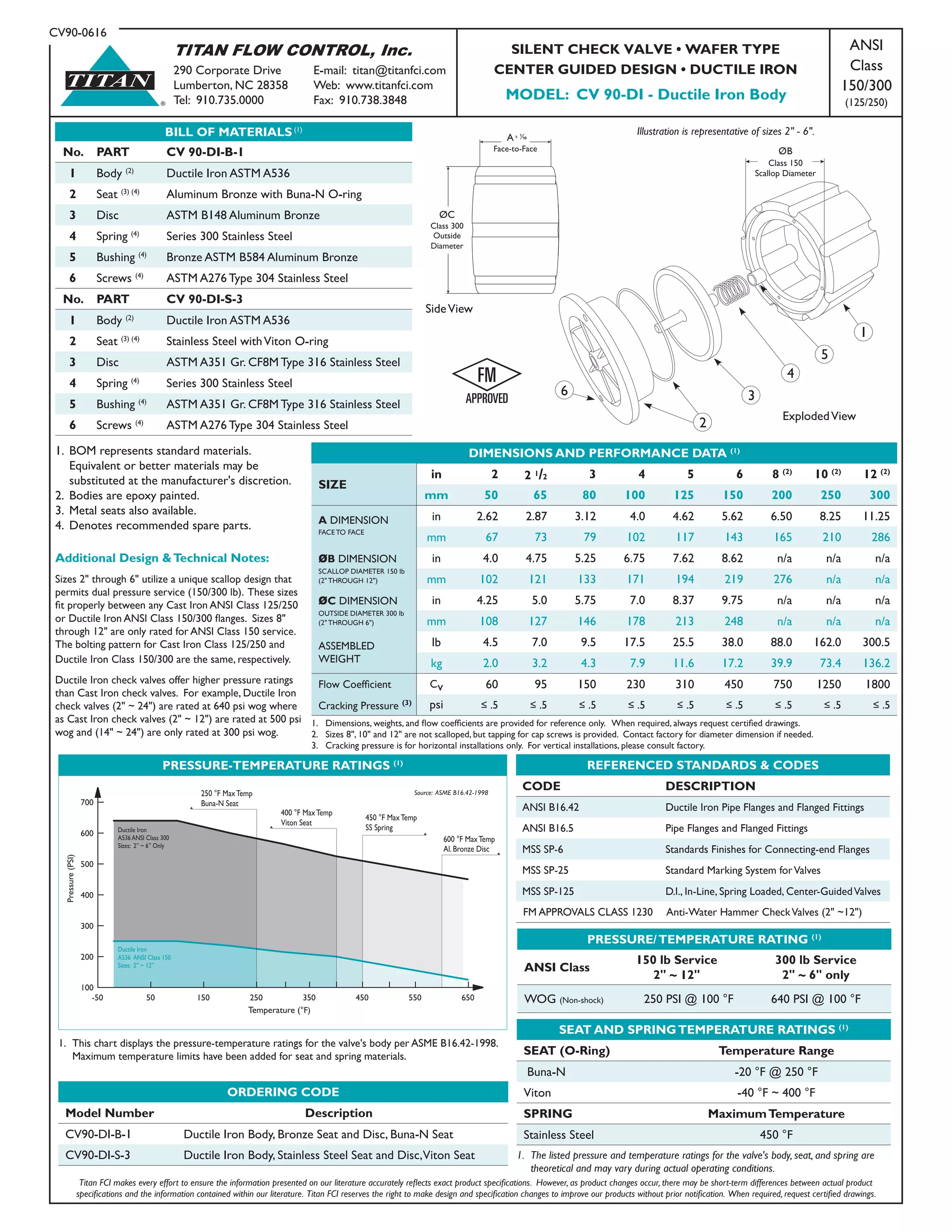
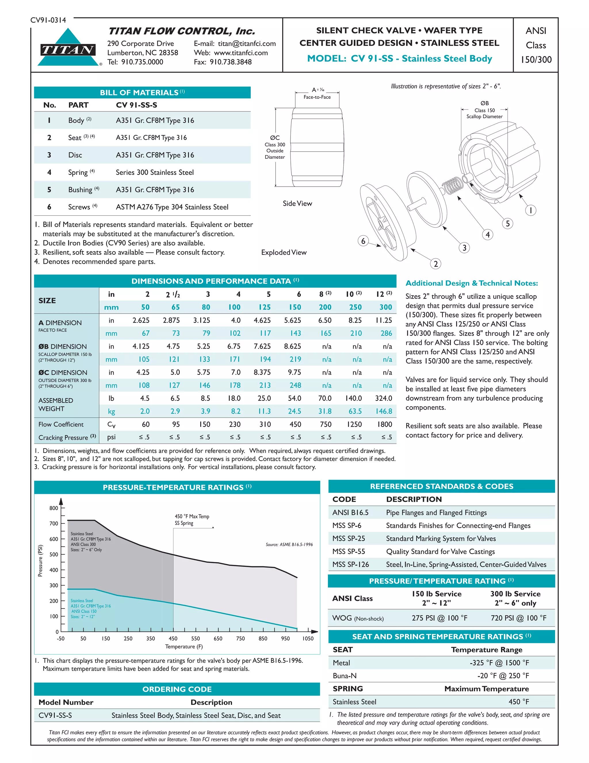
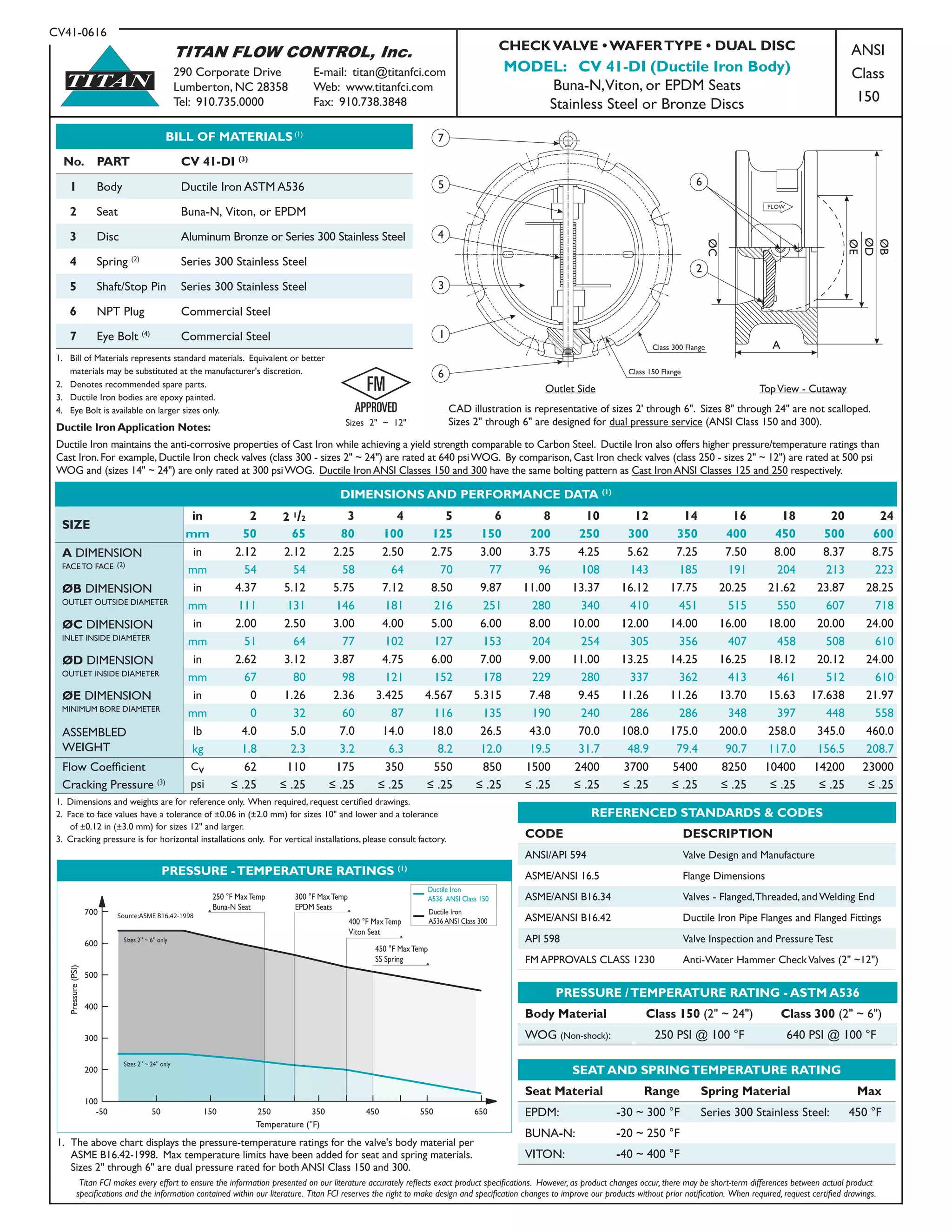
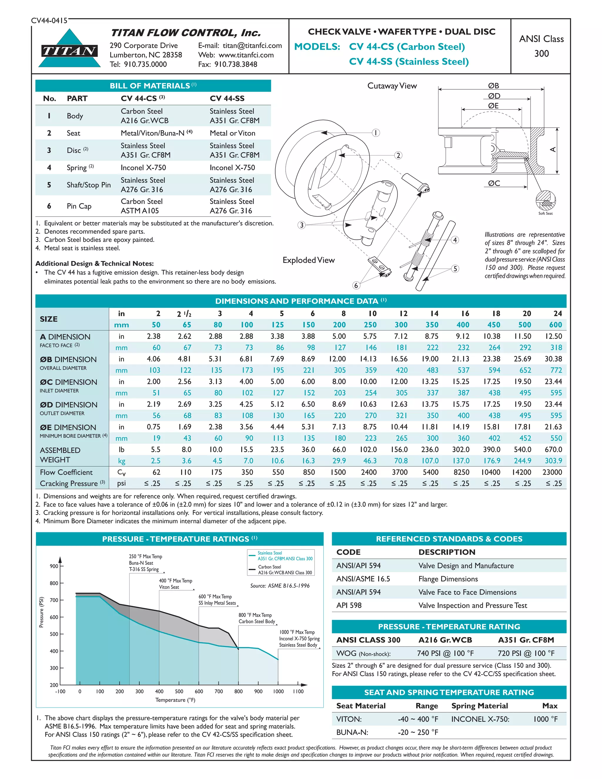
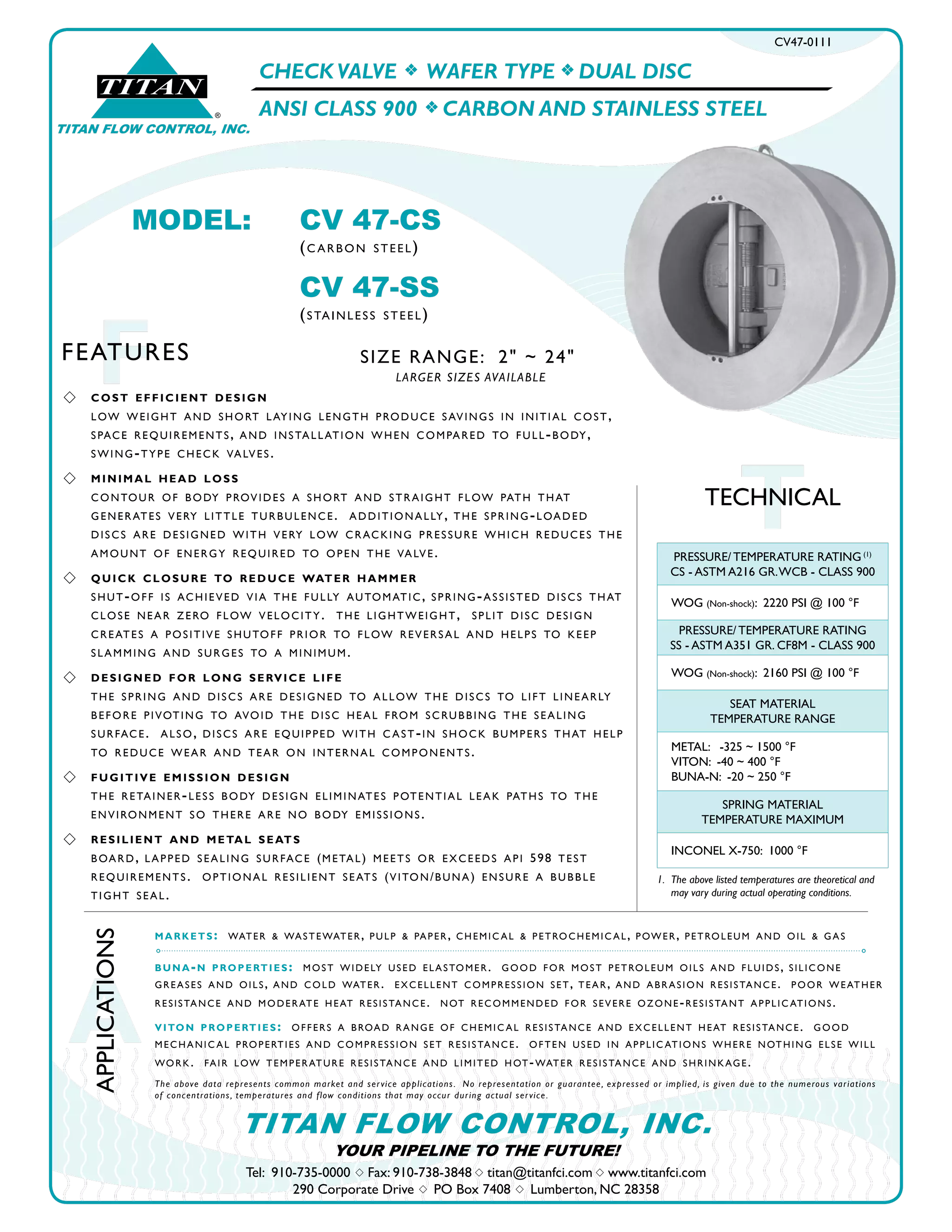
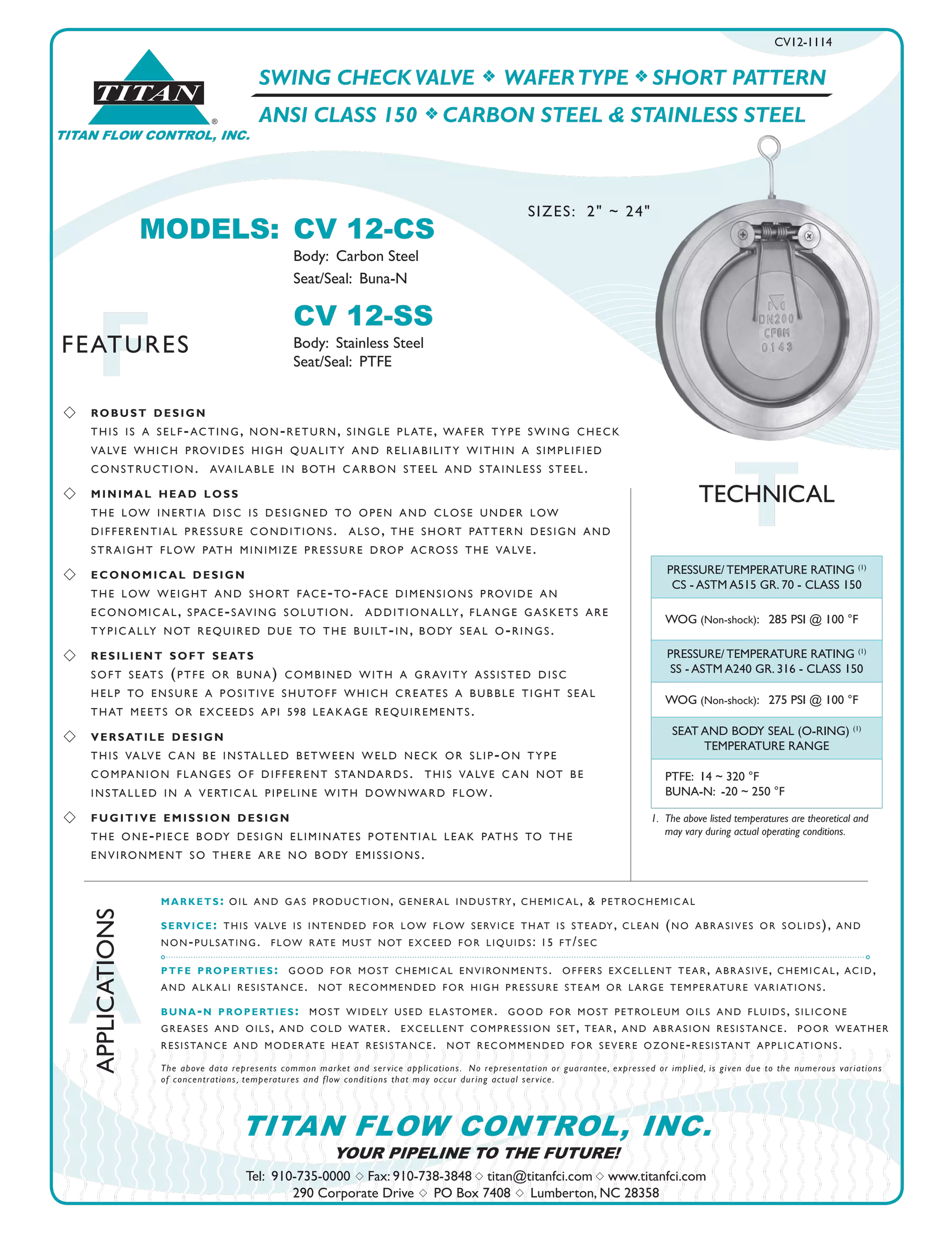
Downloaded 459 times


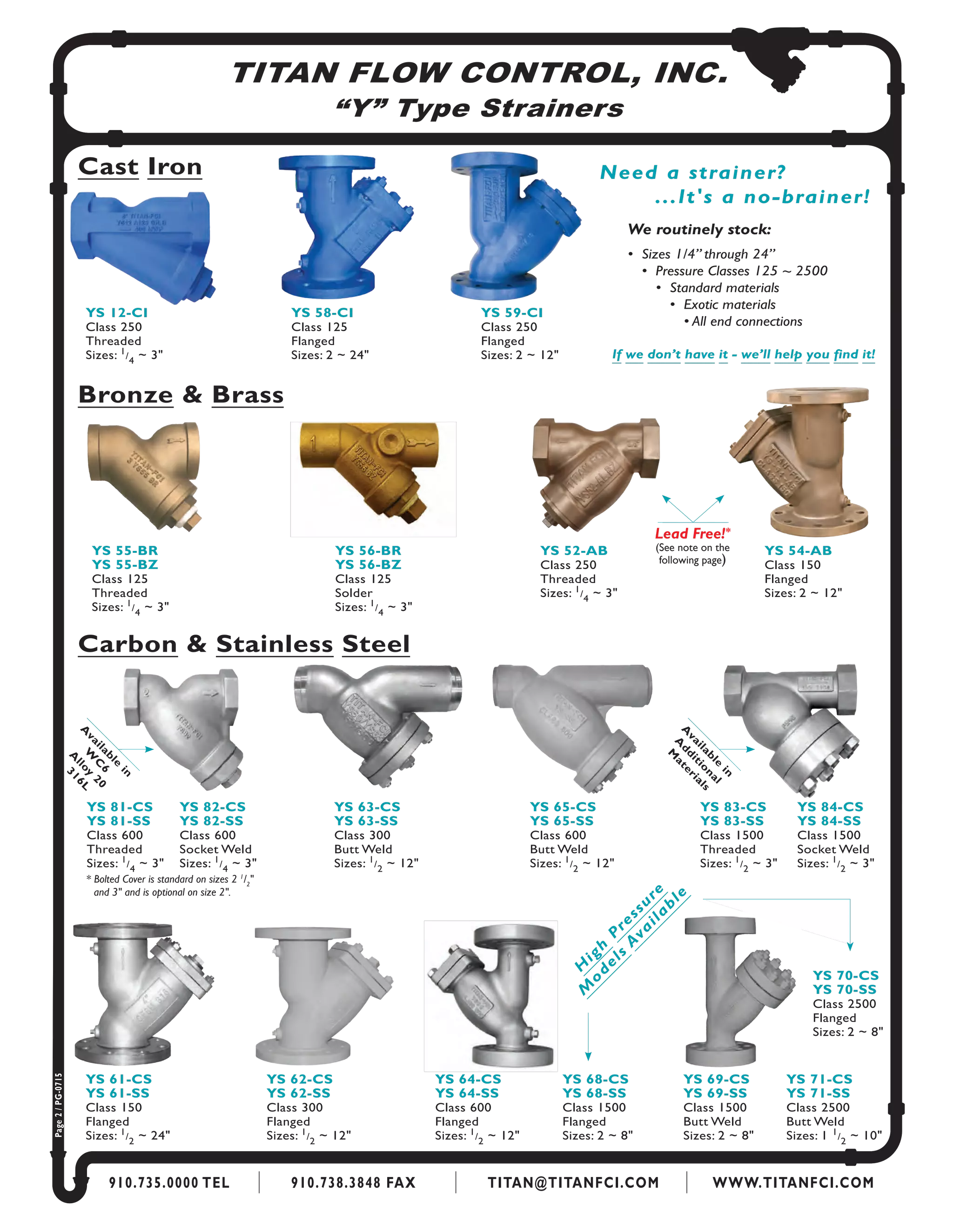


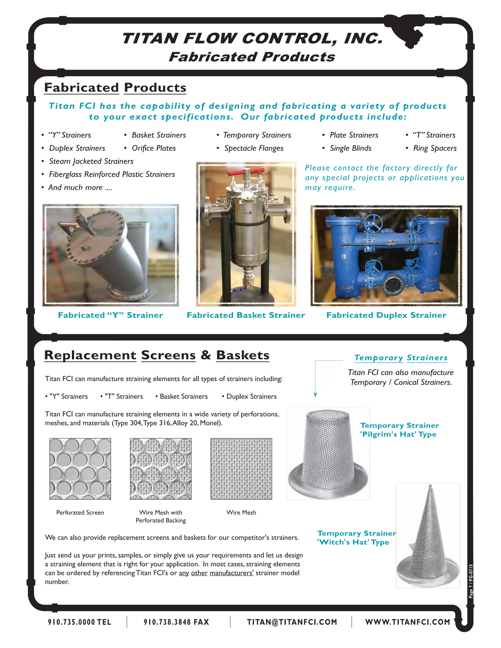


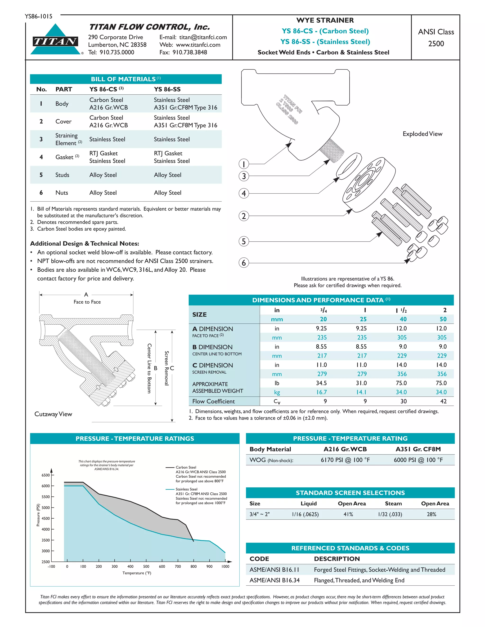
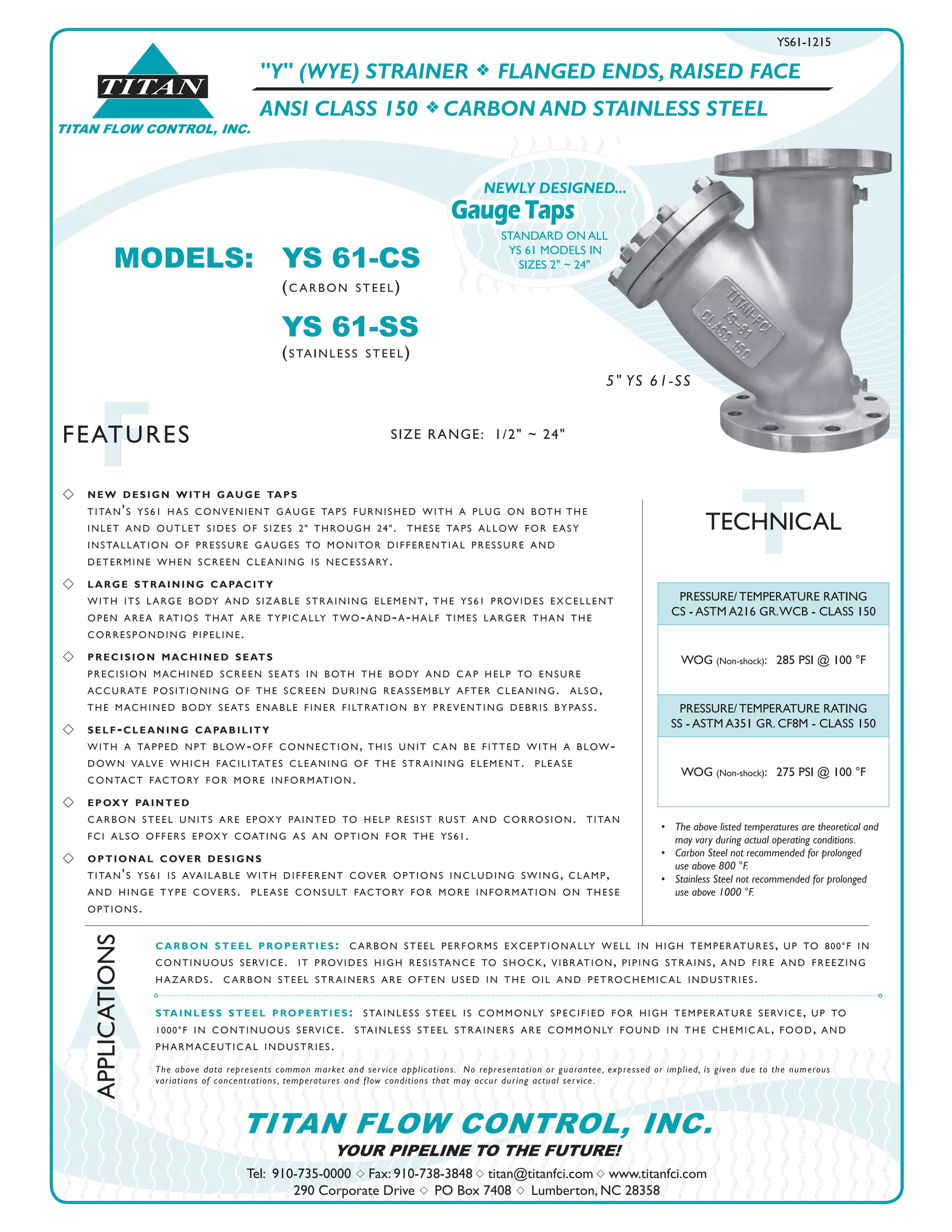

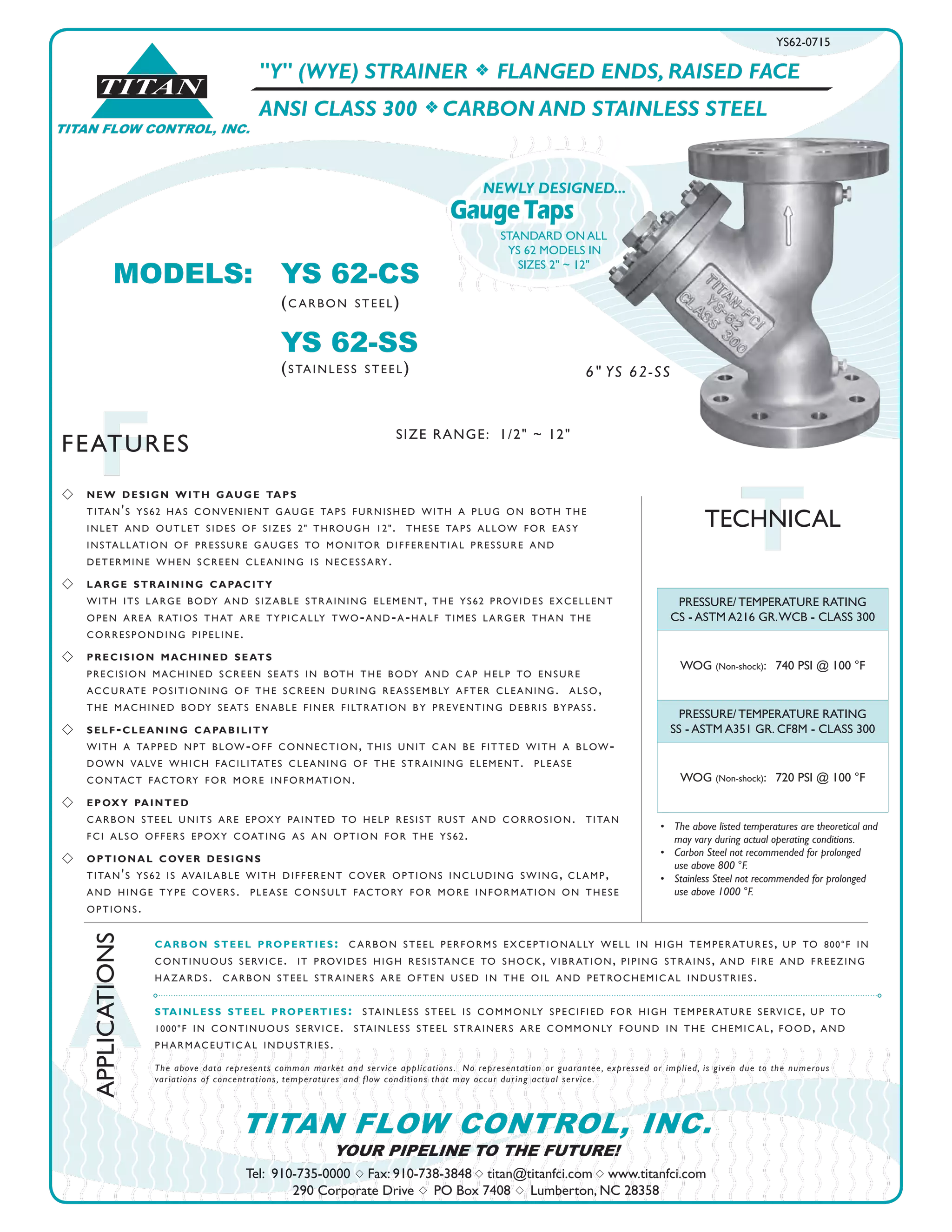


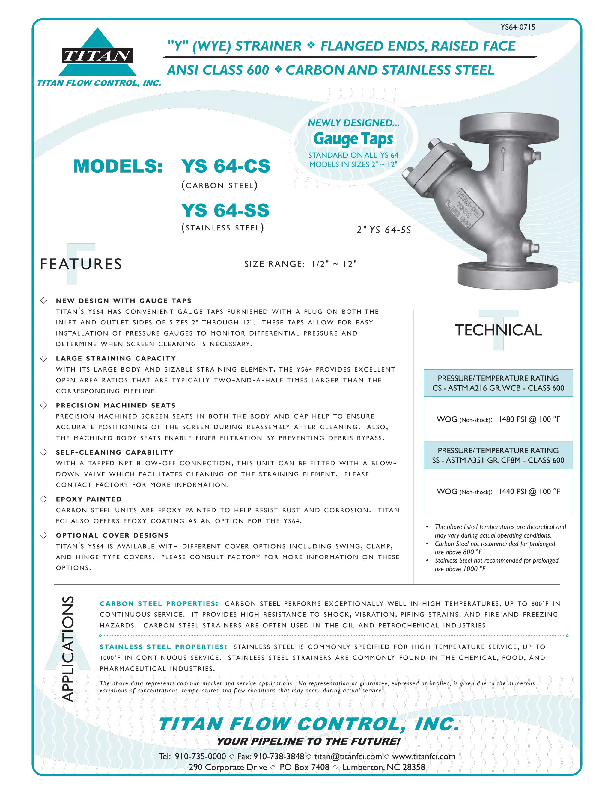


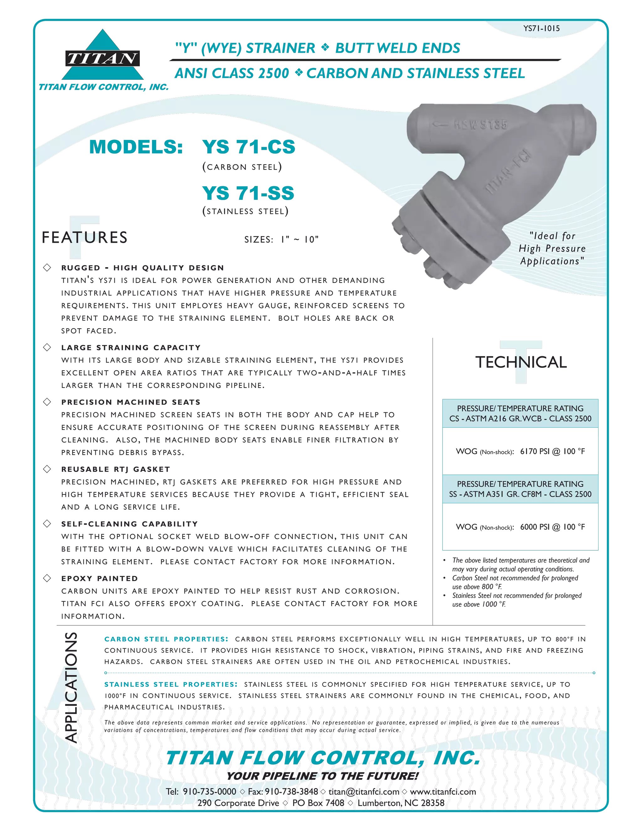
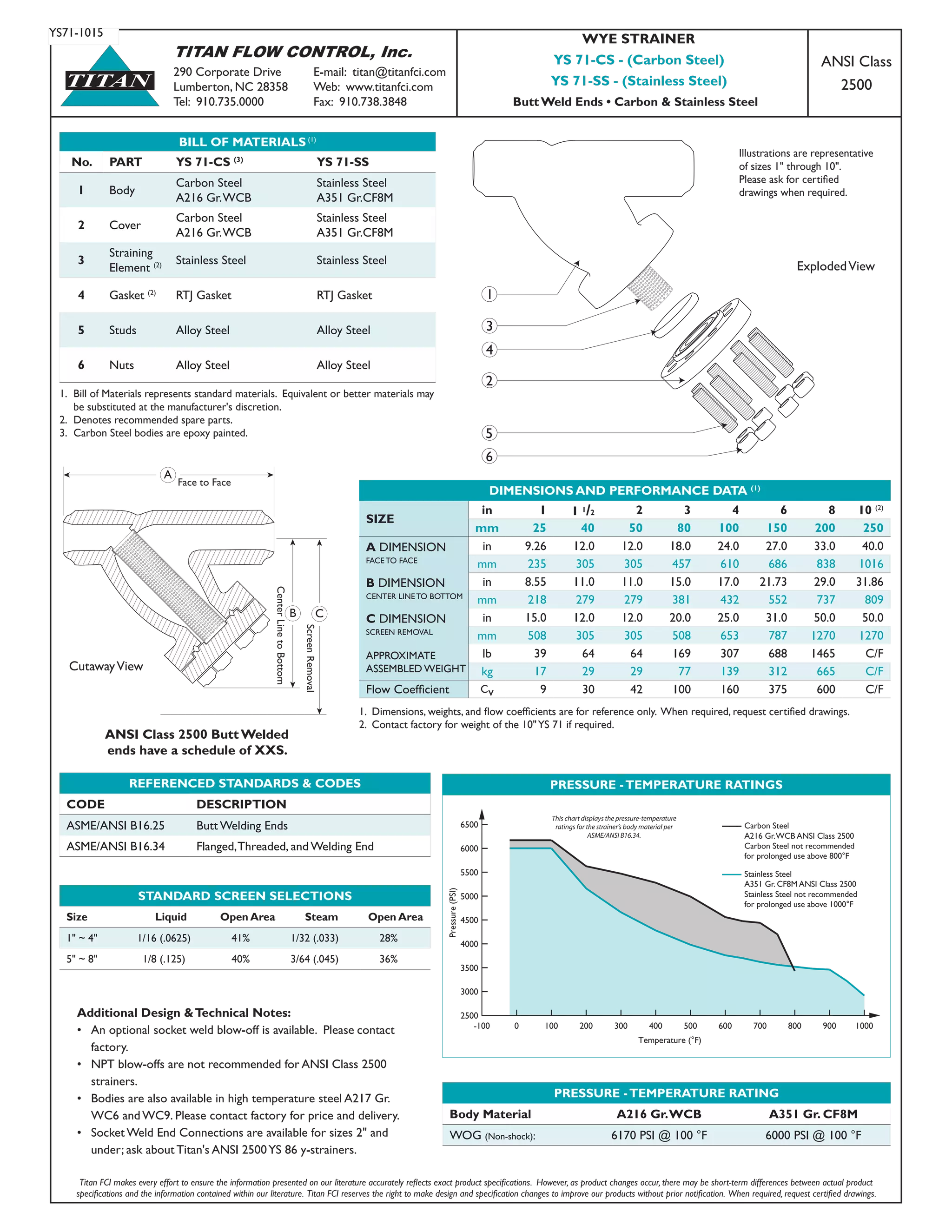
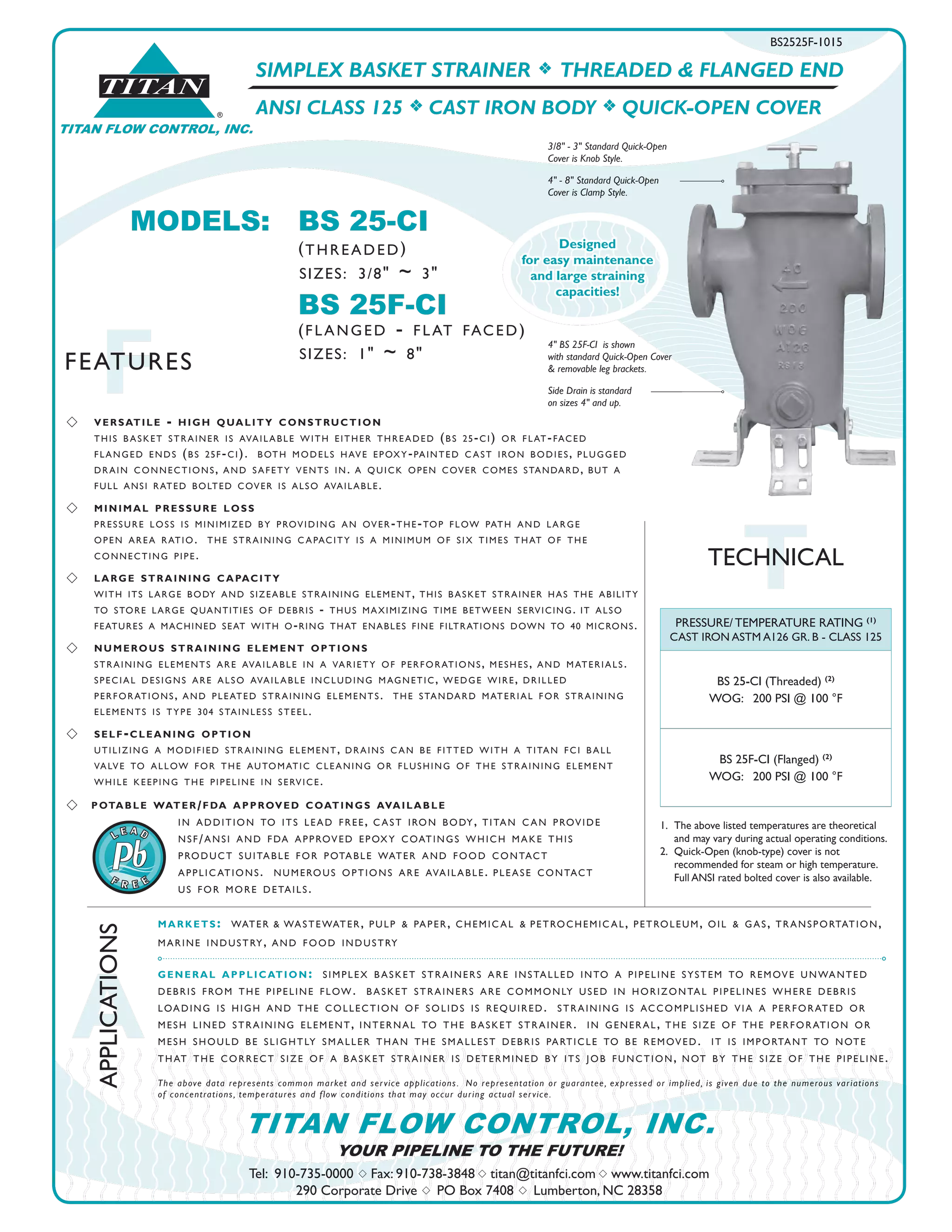

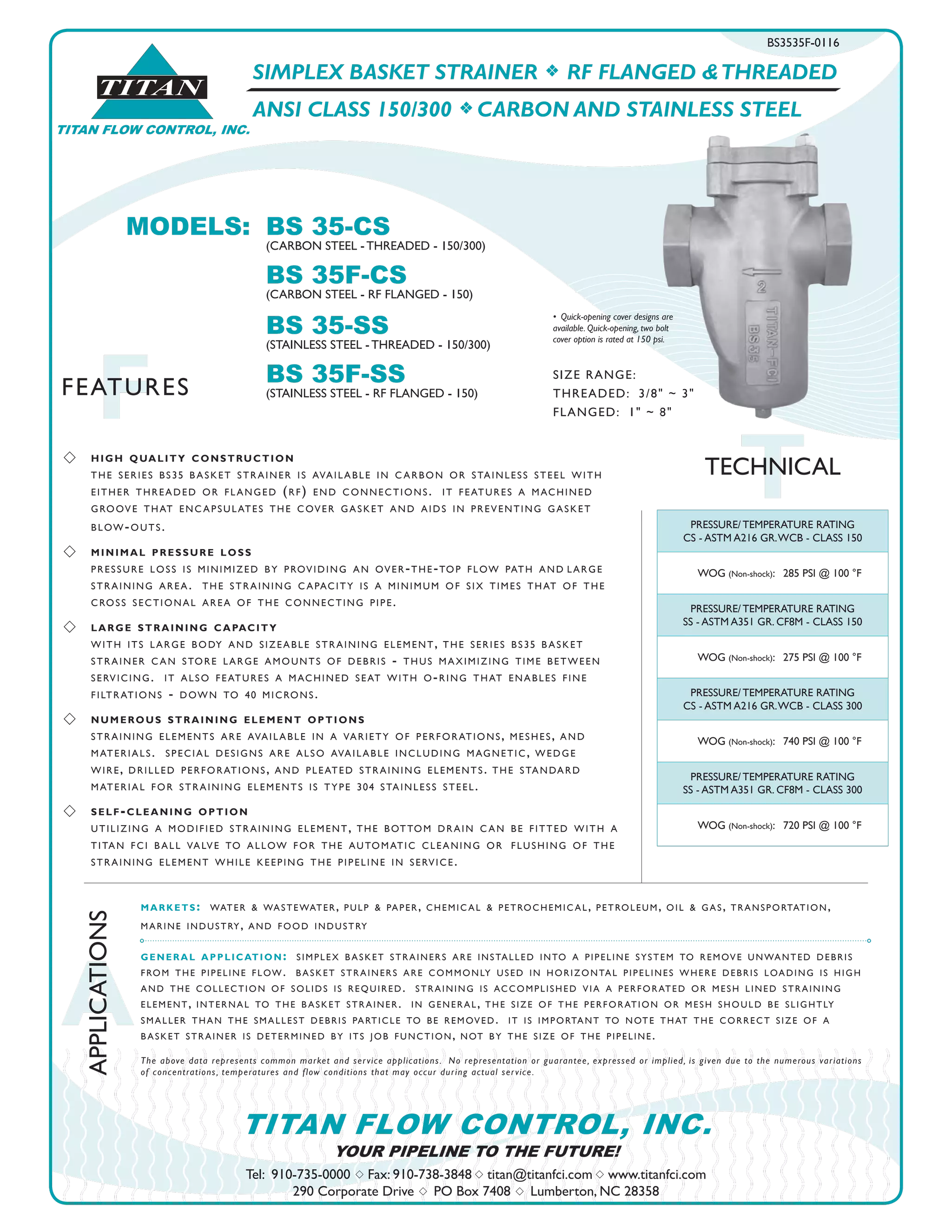


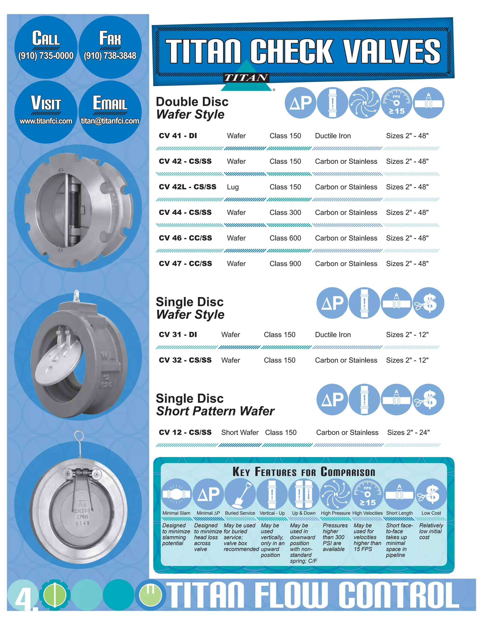
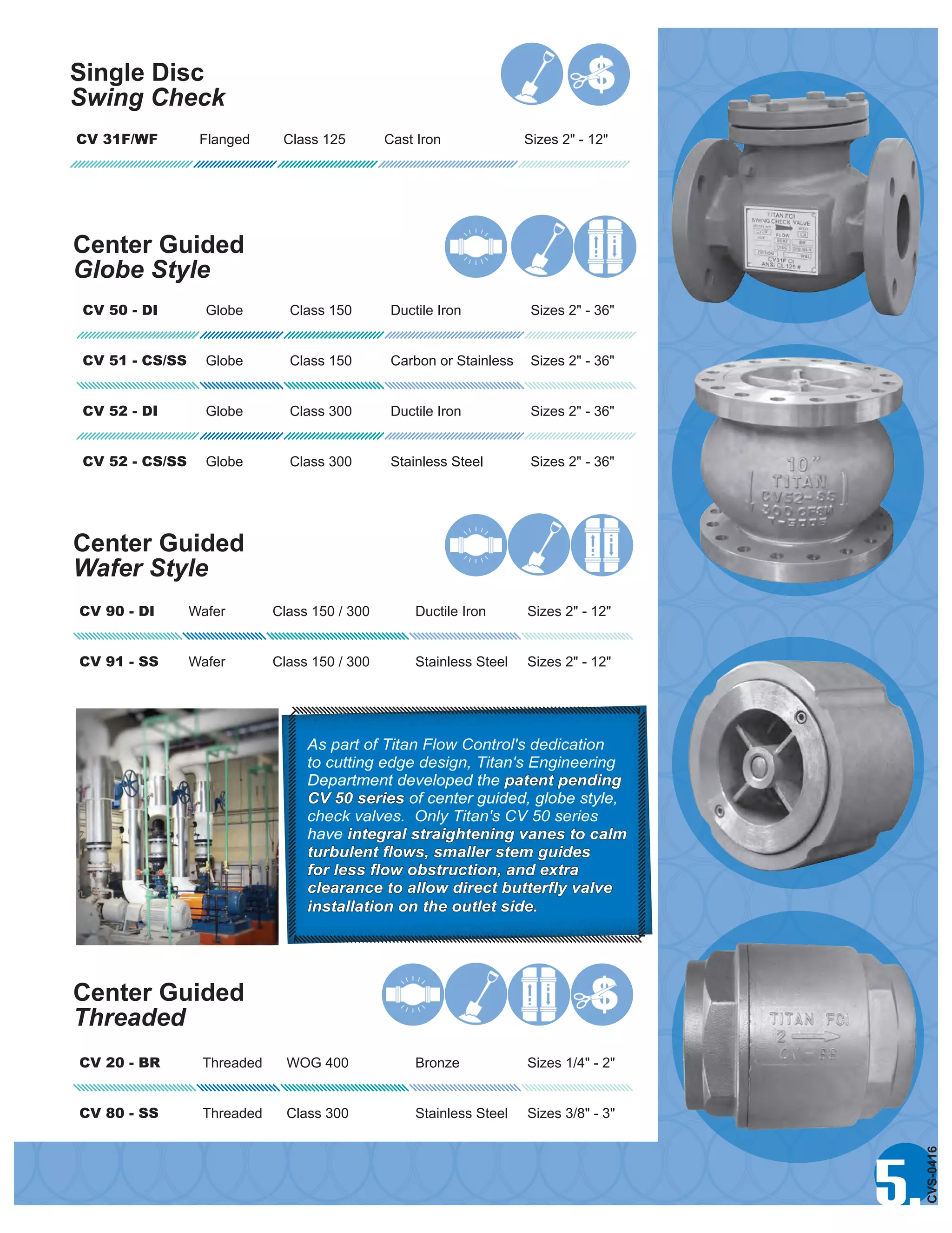

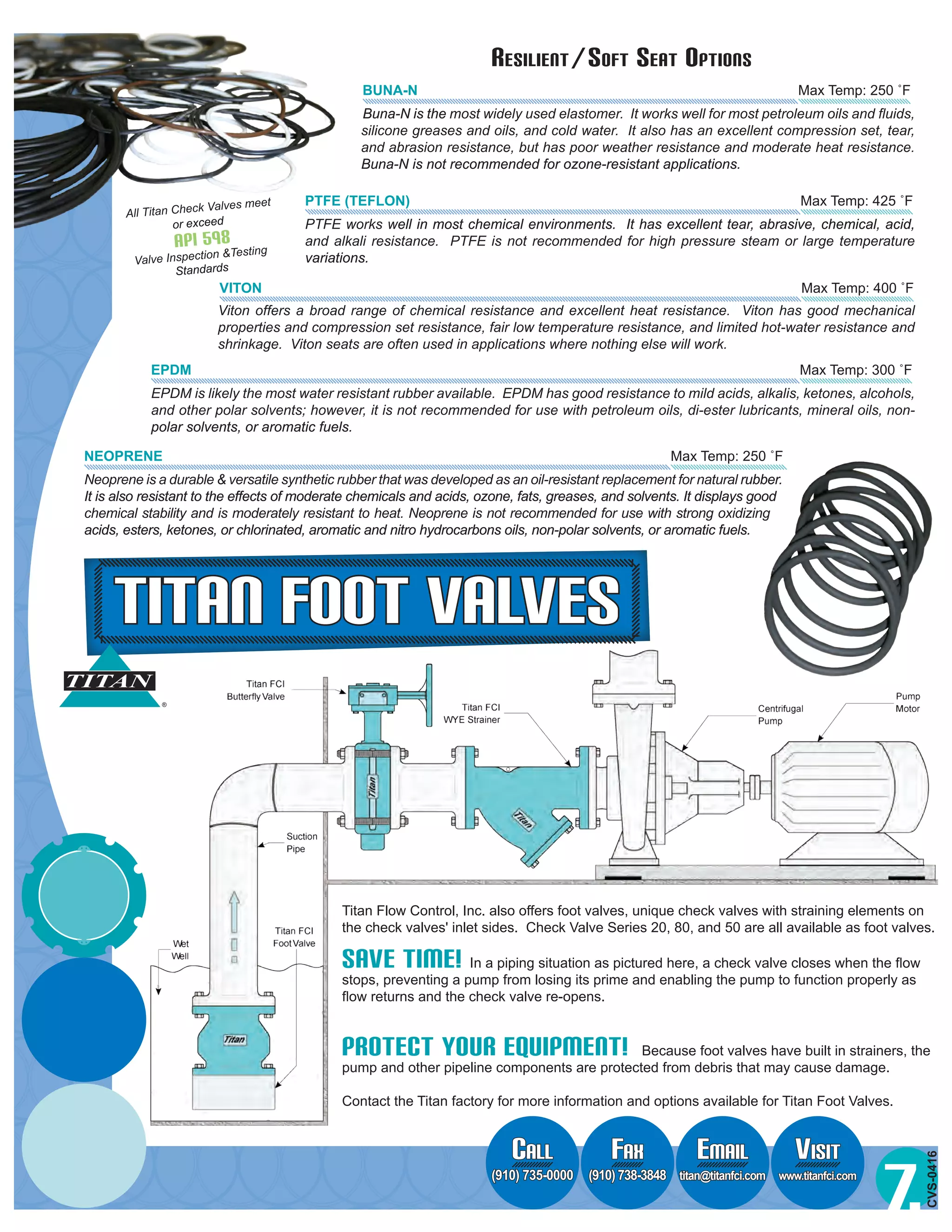


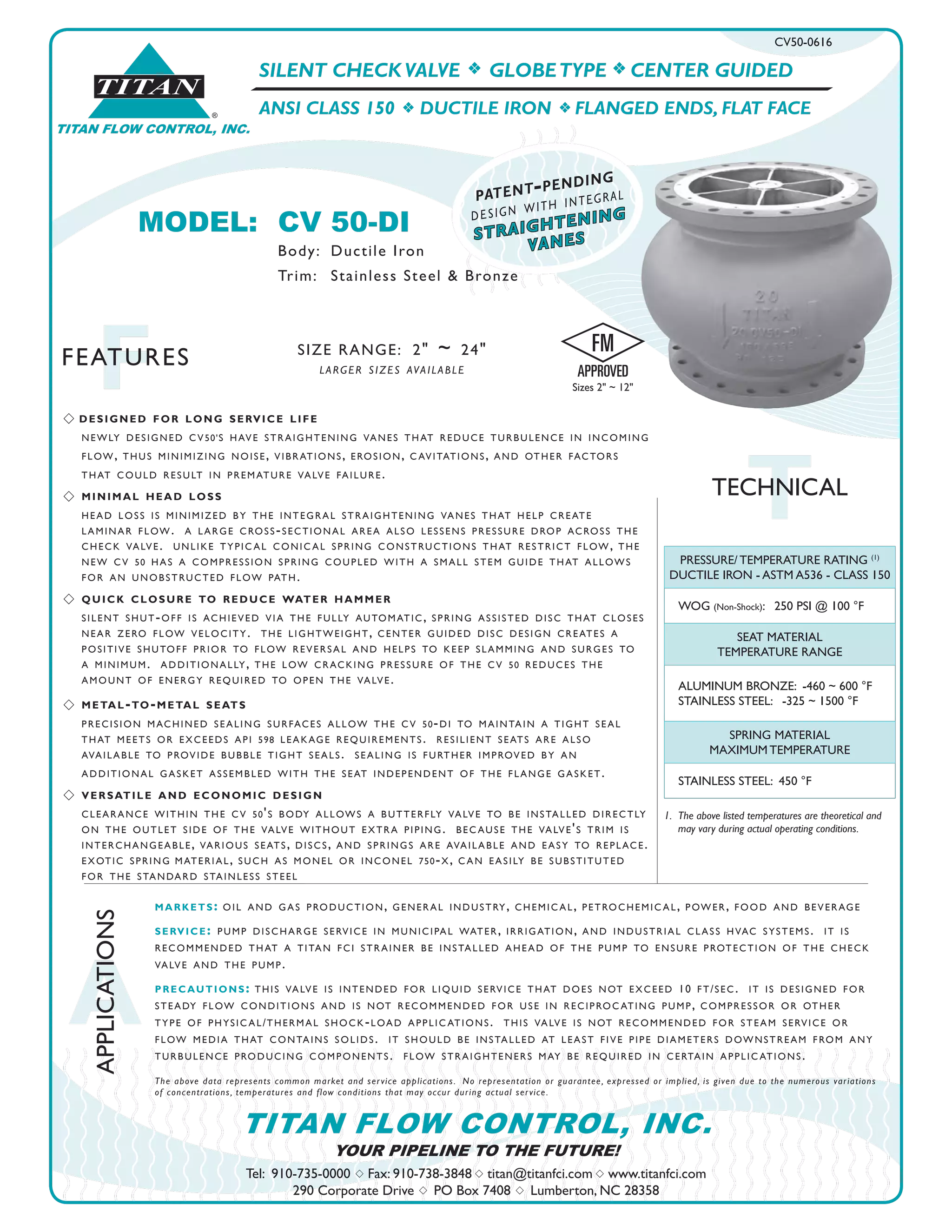


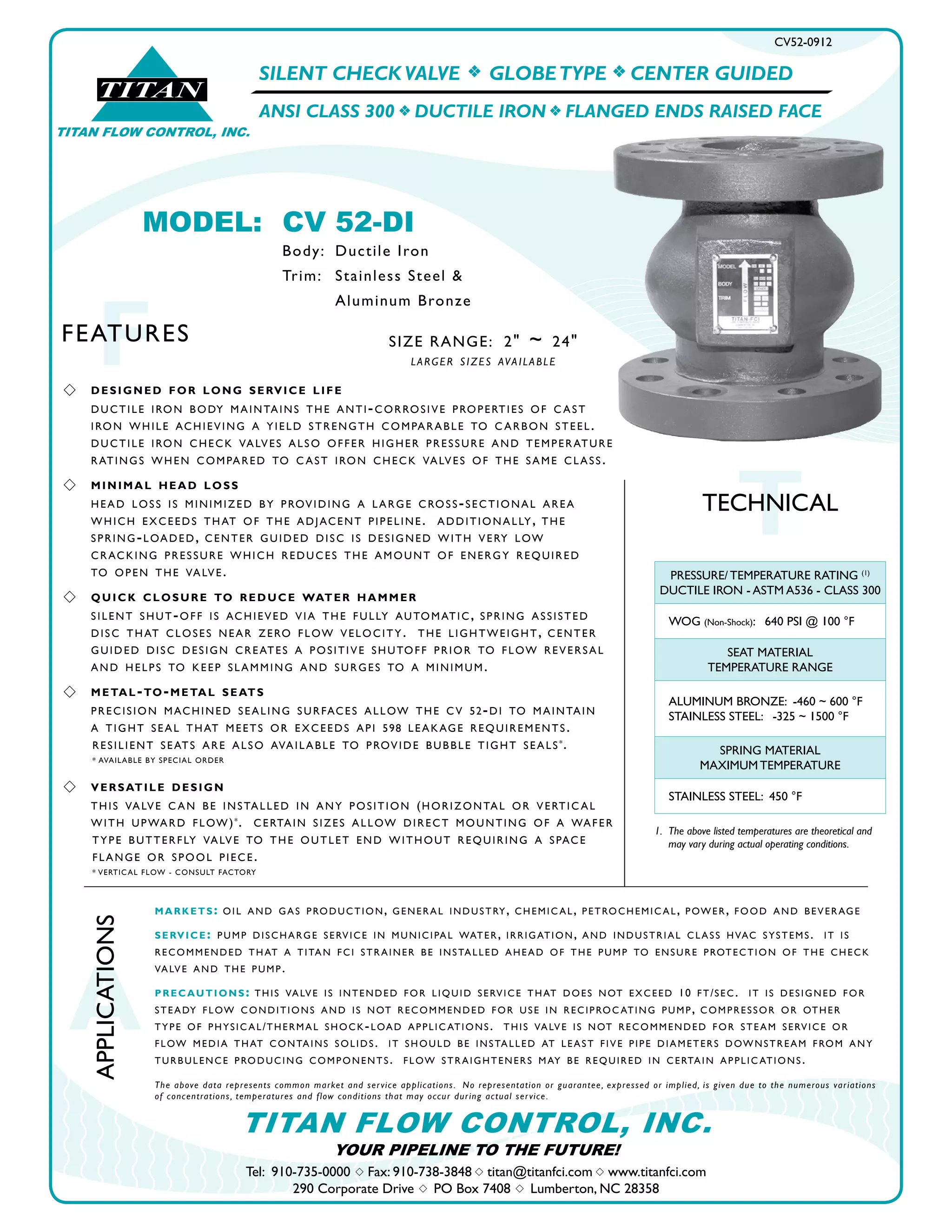

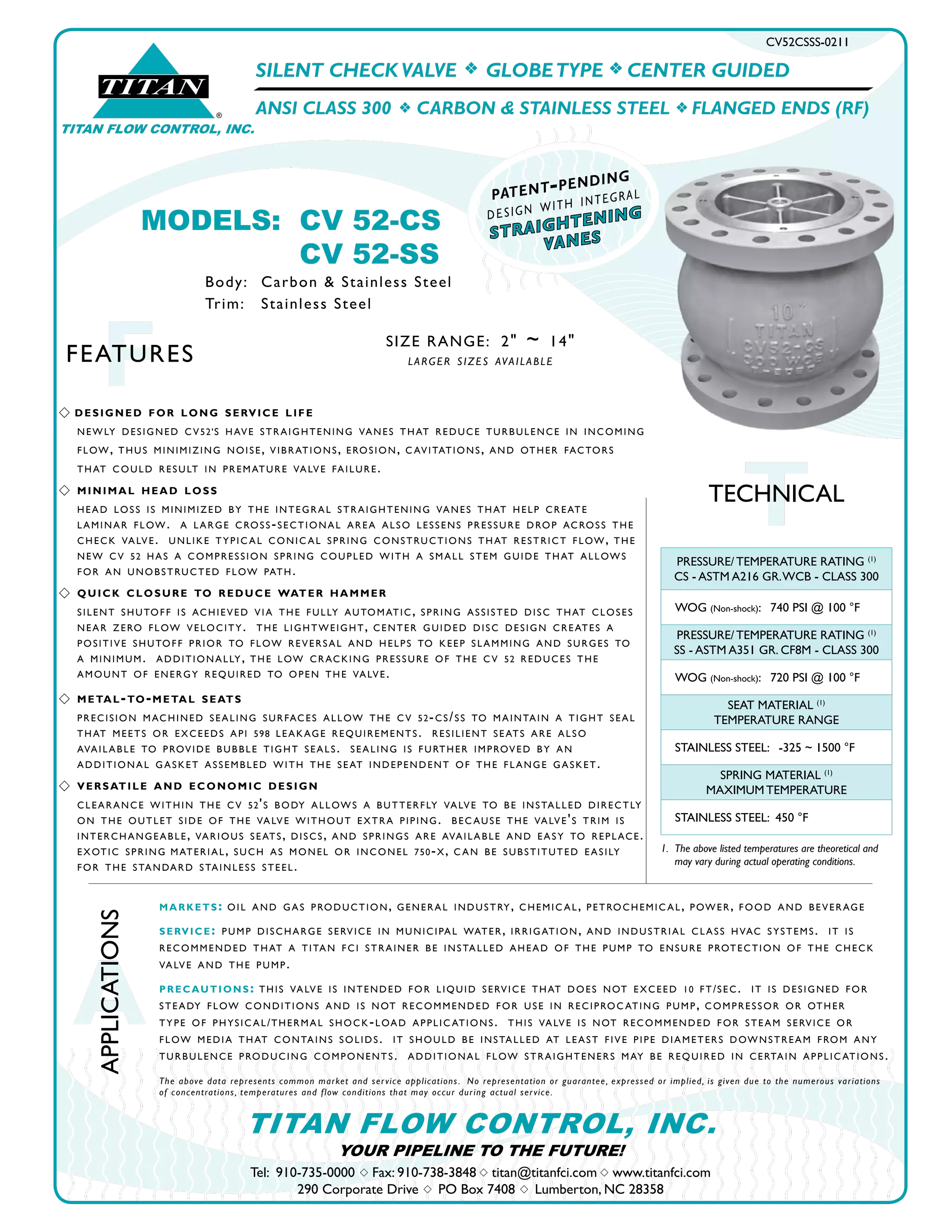
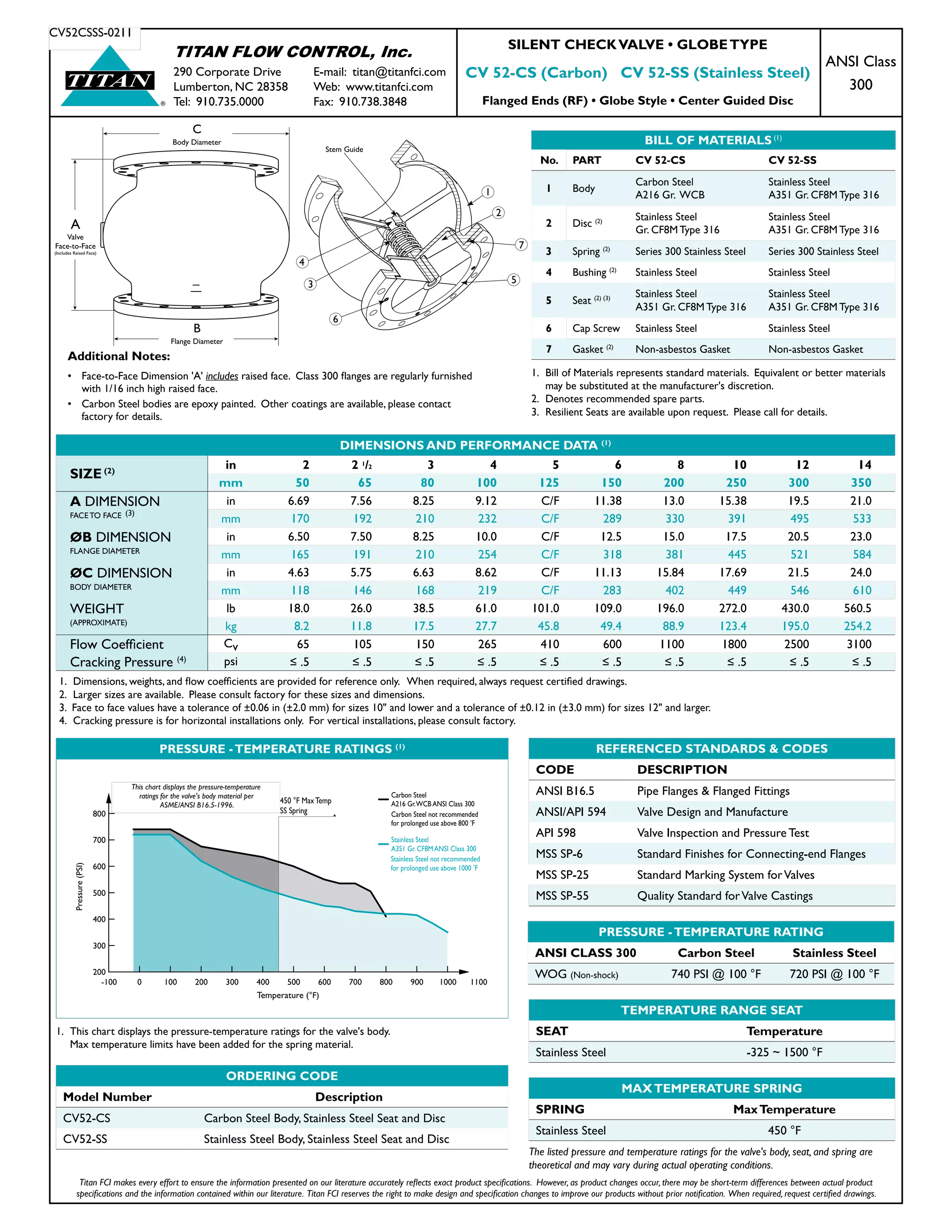


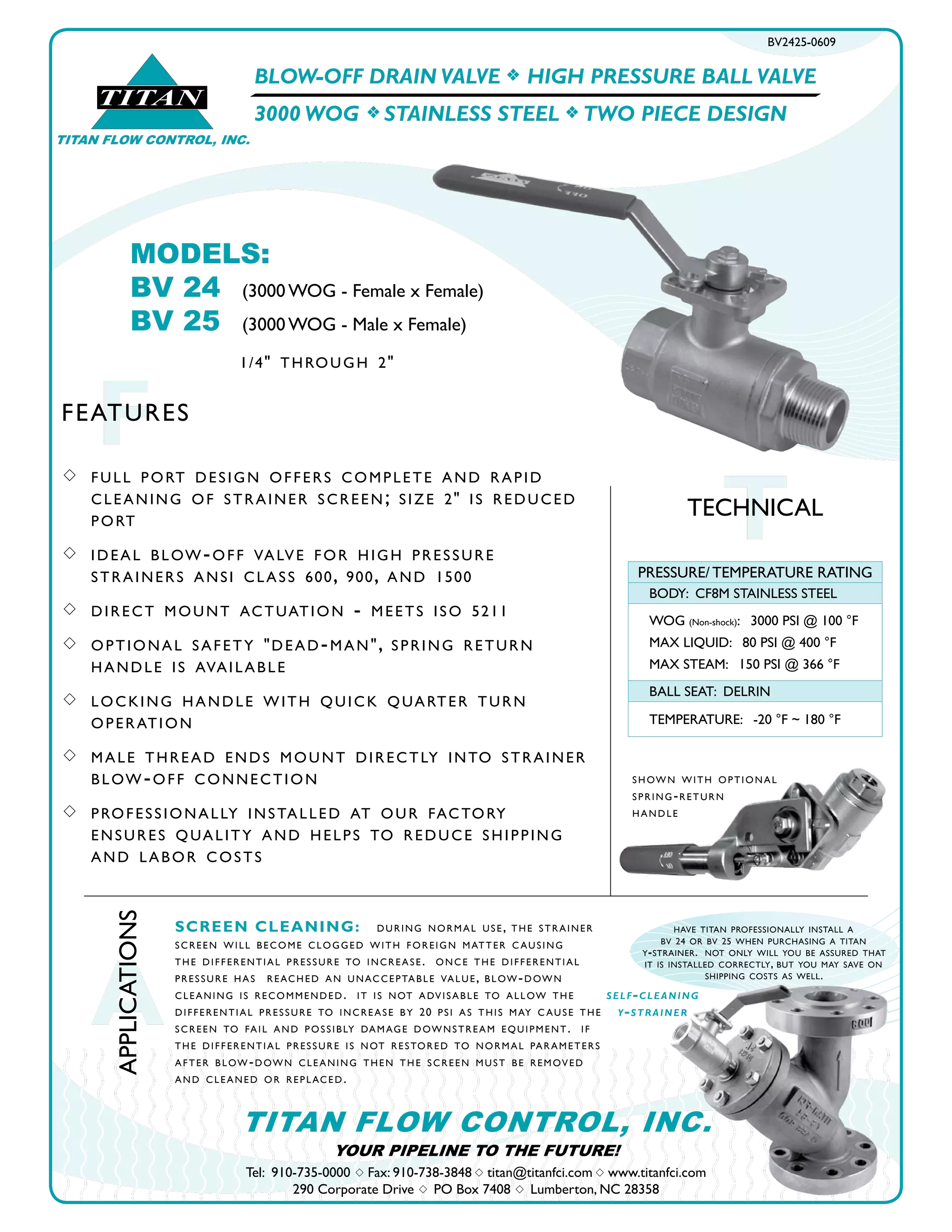

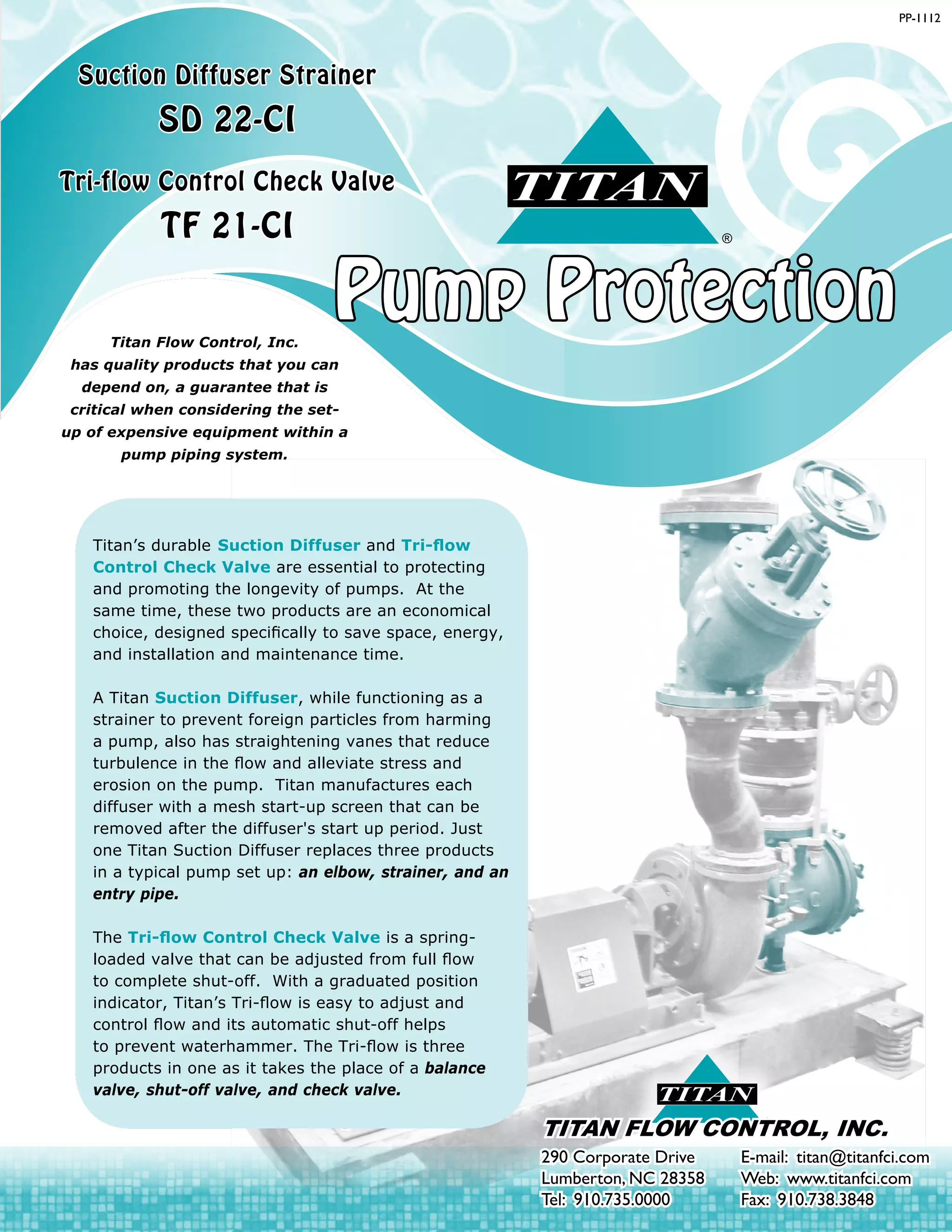


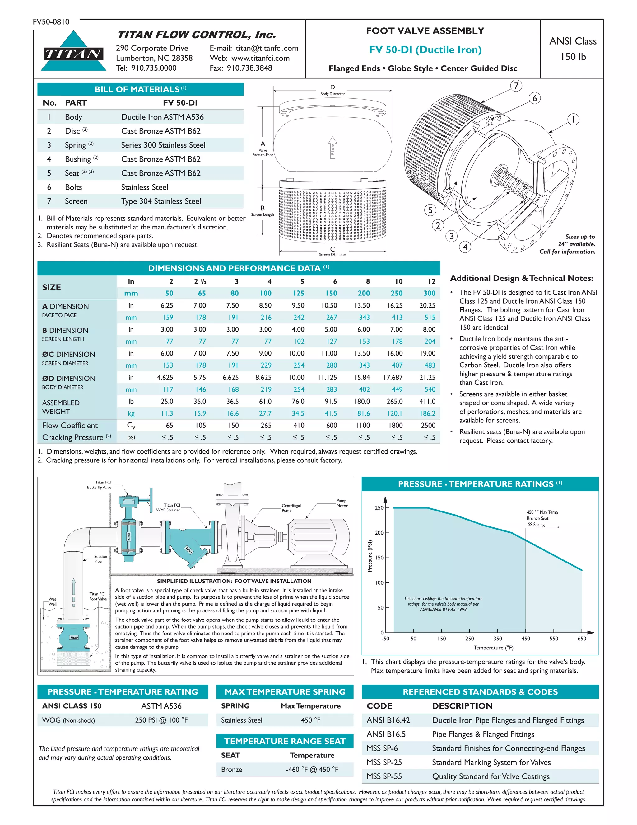


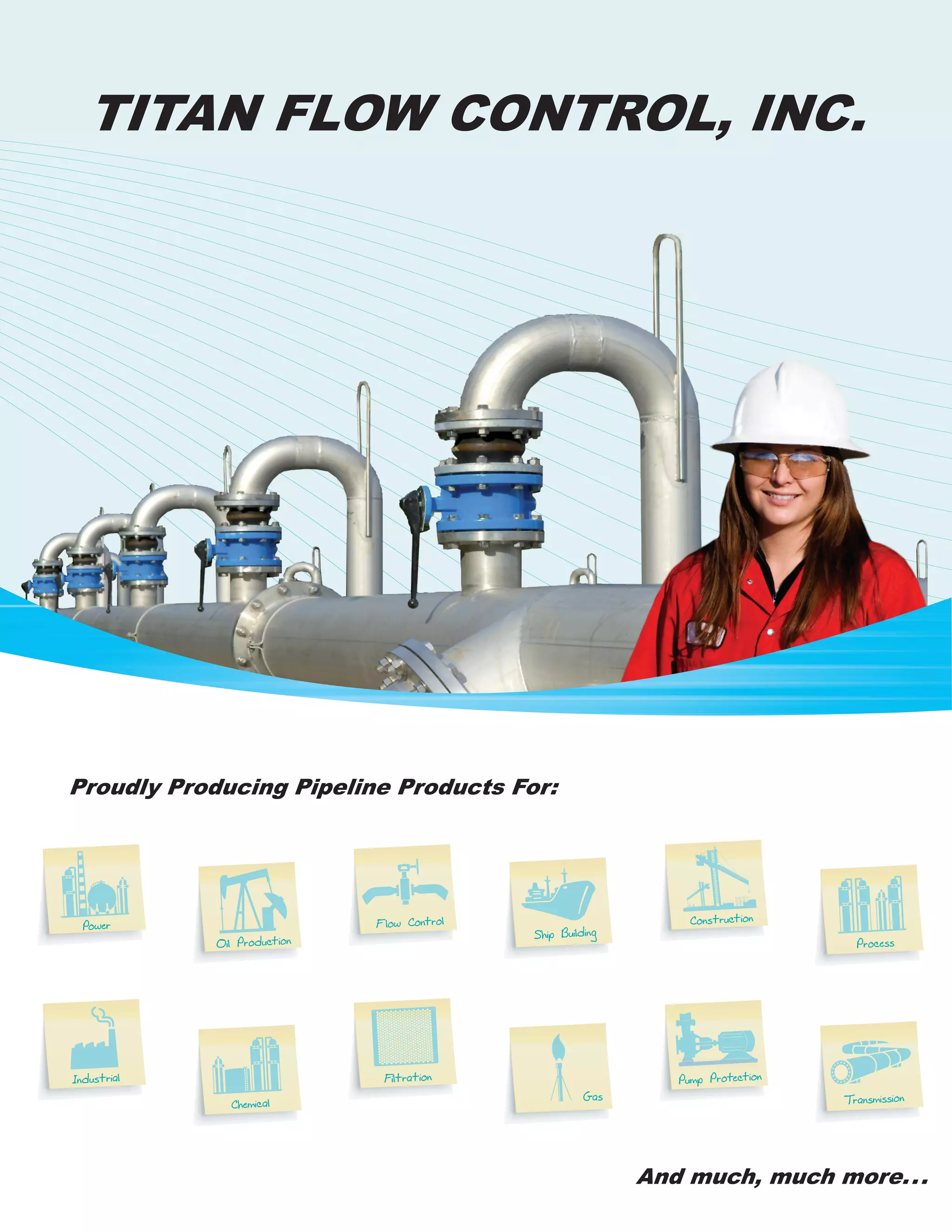

Titan Flow Control is a manufacturer of valves, strainers, and other pipeline products located in Lumberton, North Carolina. They produce check valves, butterfly valves, pipeline strainers, pump protection products, fabricated designs, and other accessories for industrial and commercial applications. Founded in 2000 by industry veterans, Titan Flow Control occupies over 70,000 square feet of manufacturing space. Their product lines include Y-strainers, basket strainers, duplex strainers, fabricated products, specialty products, pump protection, check valves, butterfly valves, and ball valves.


