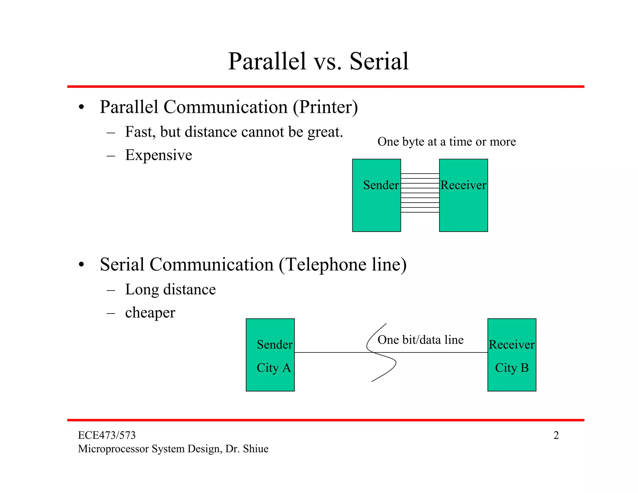
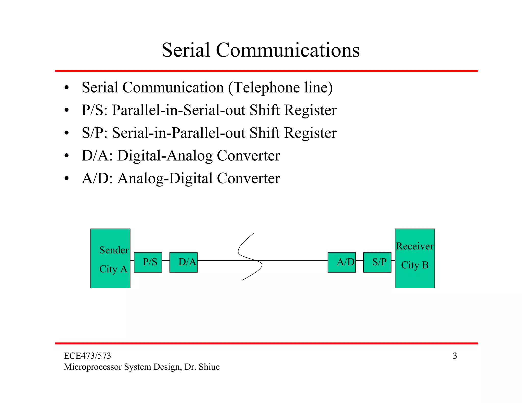
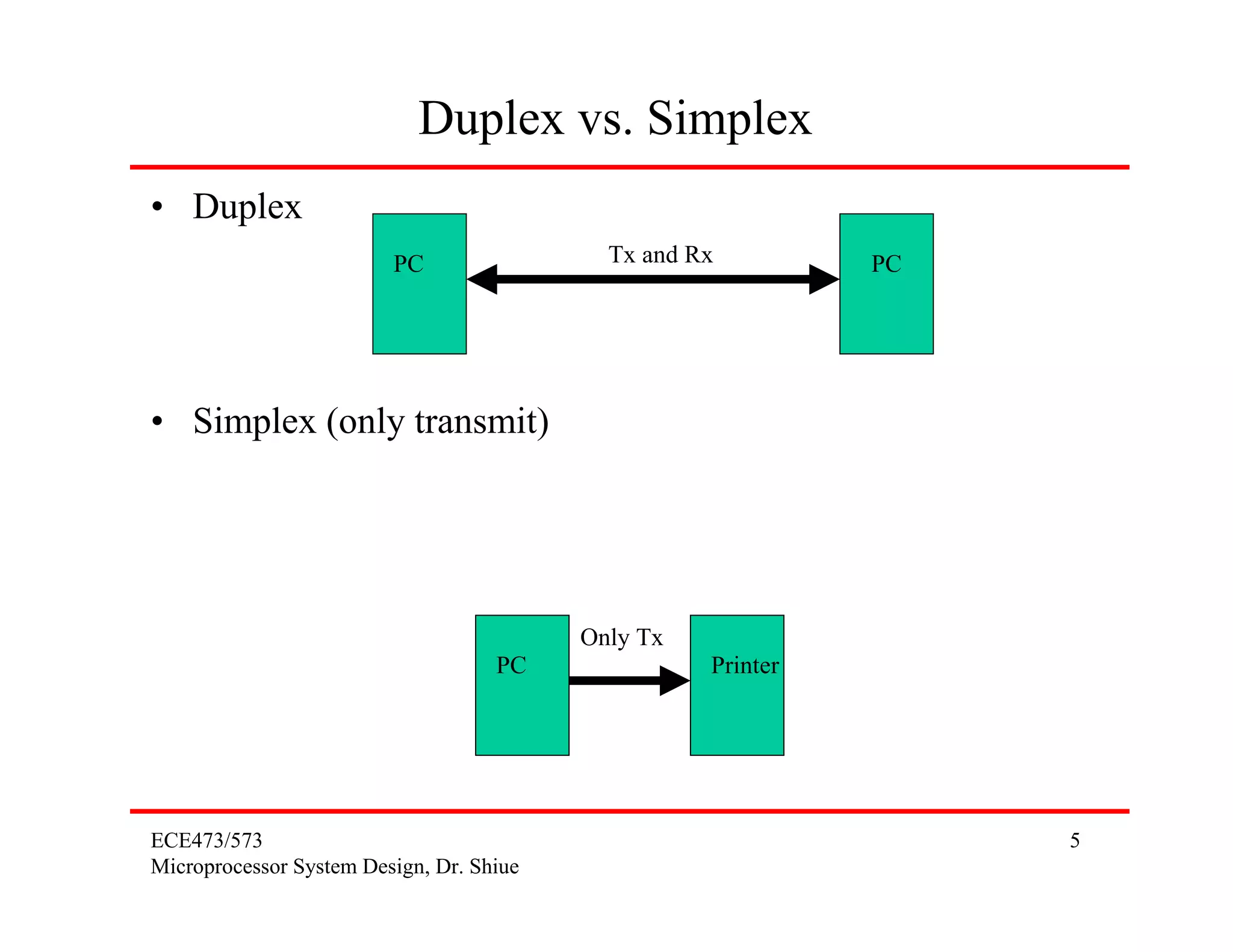
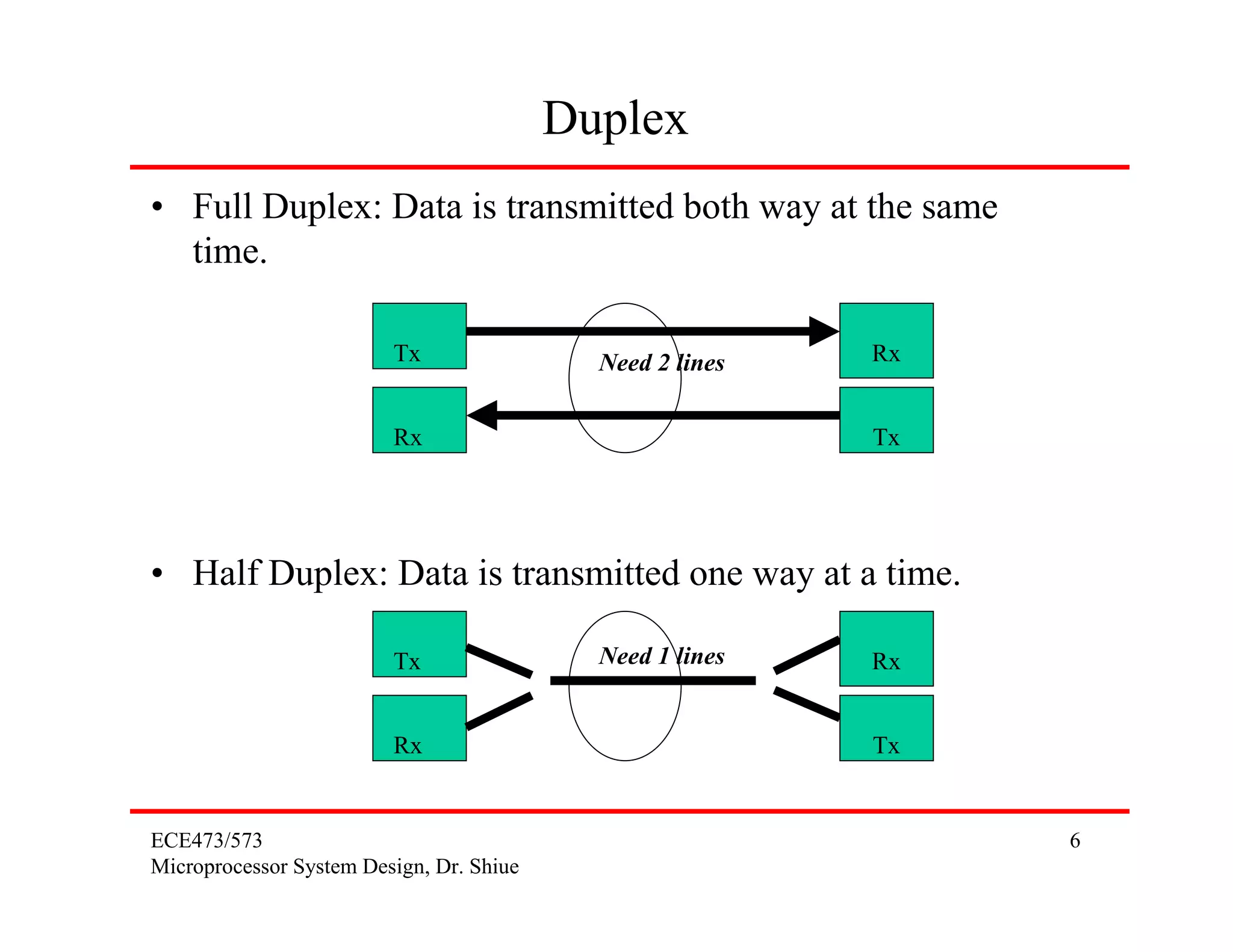
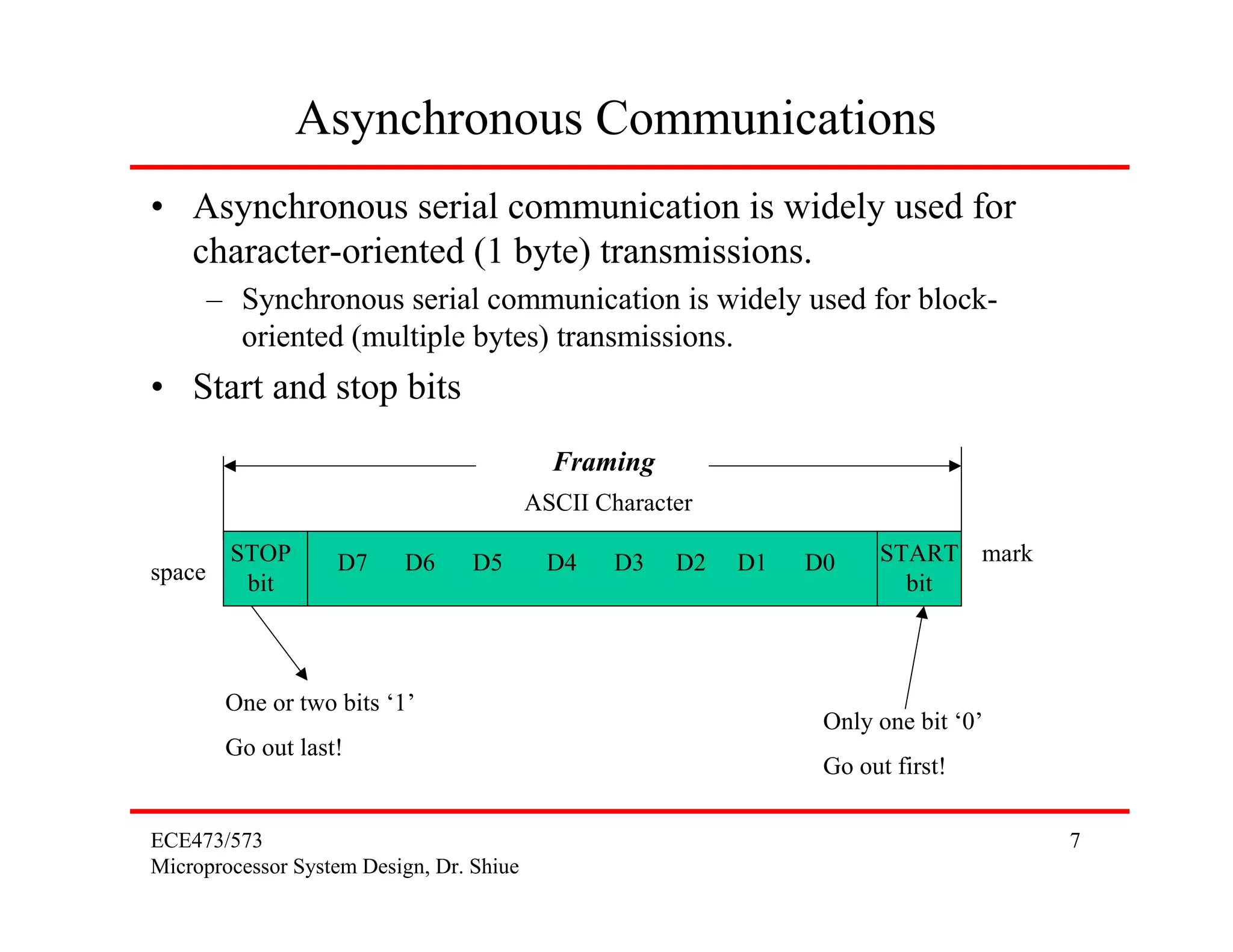
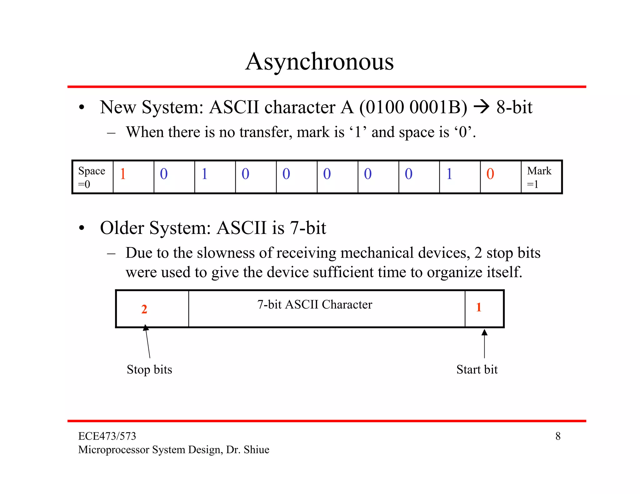
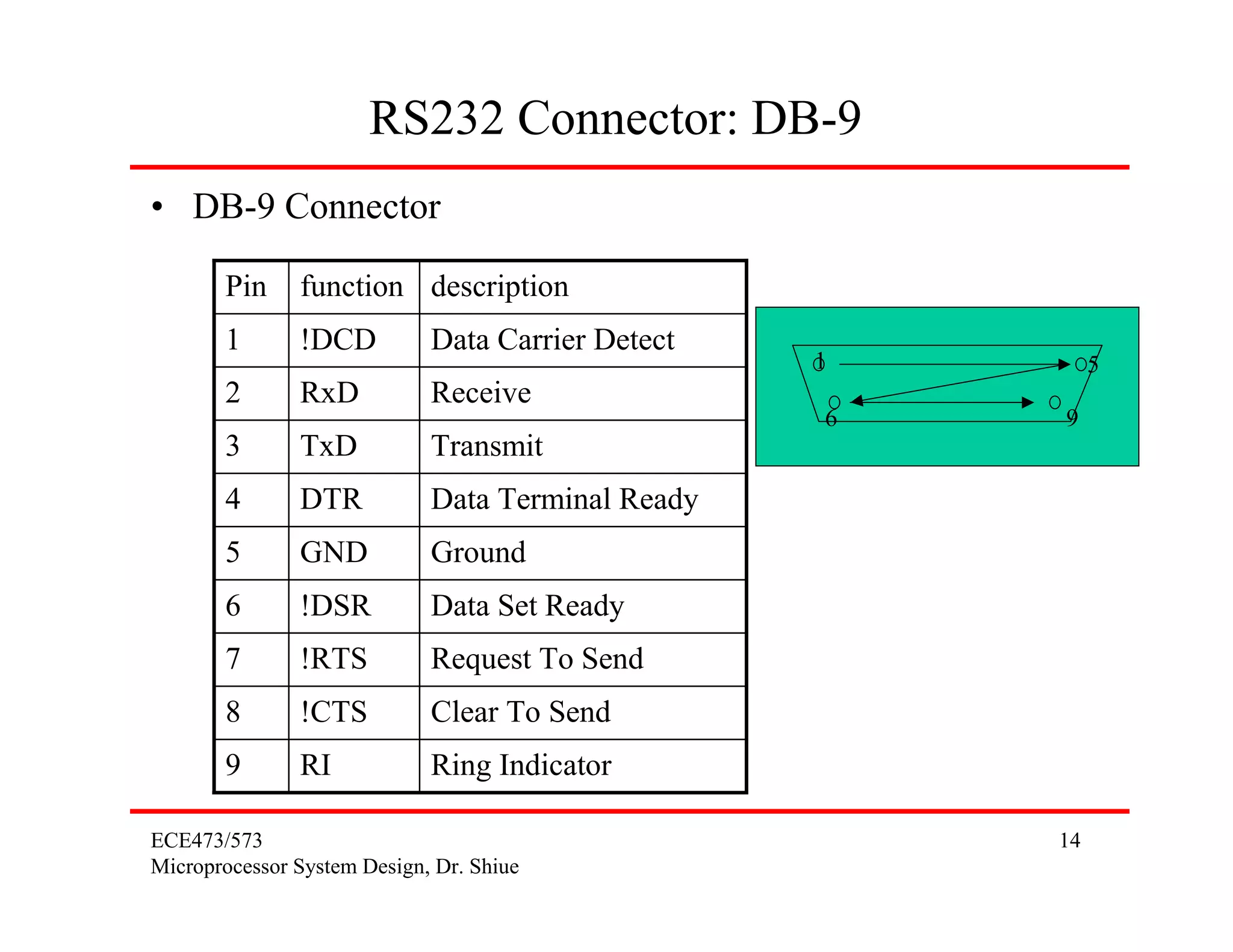
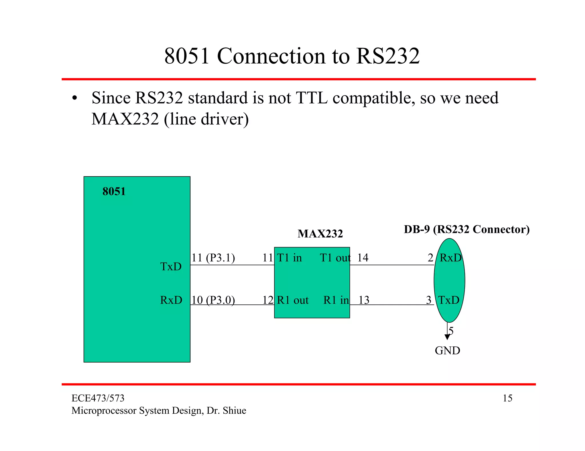
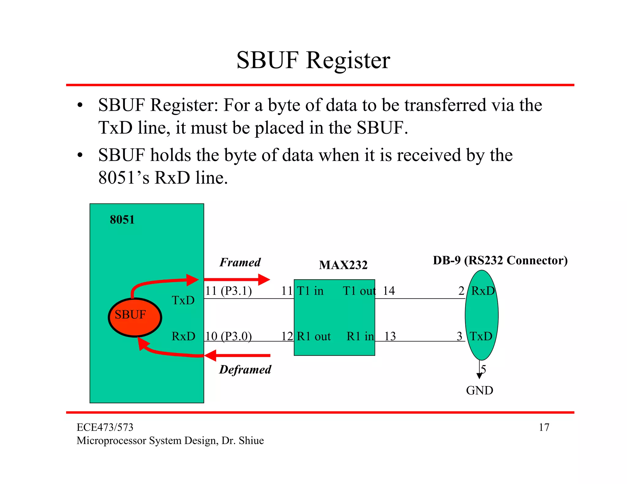
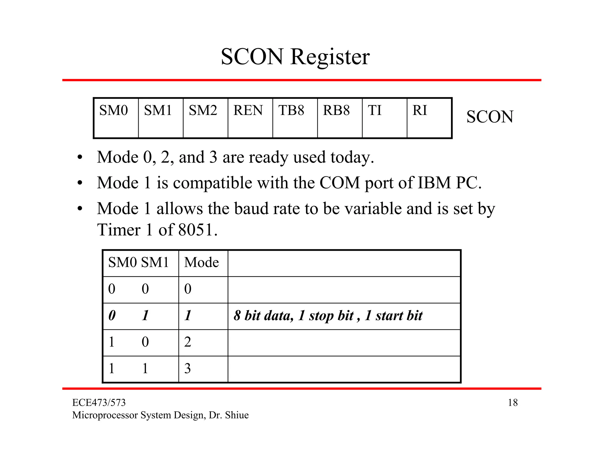
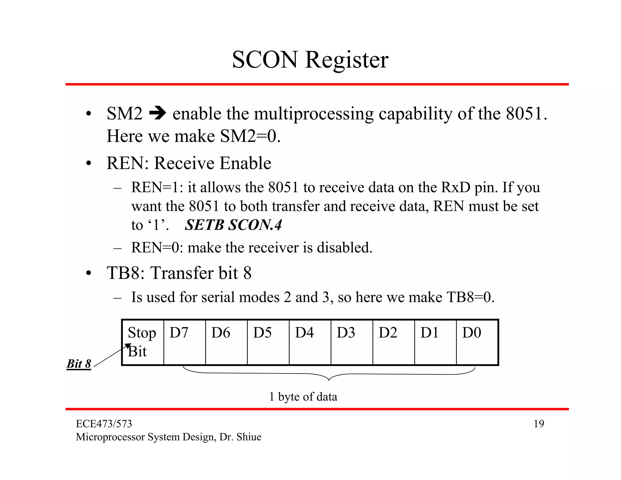
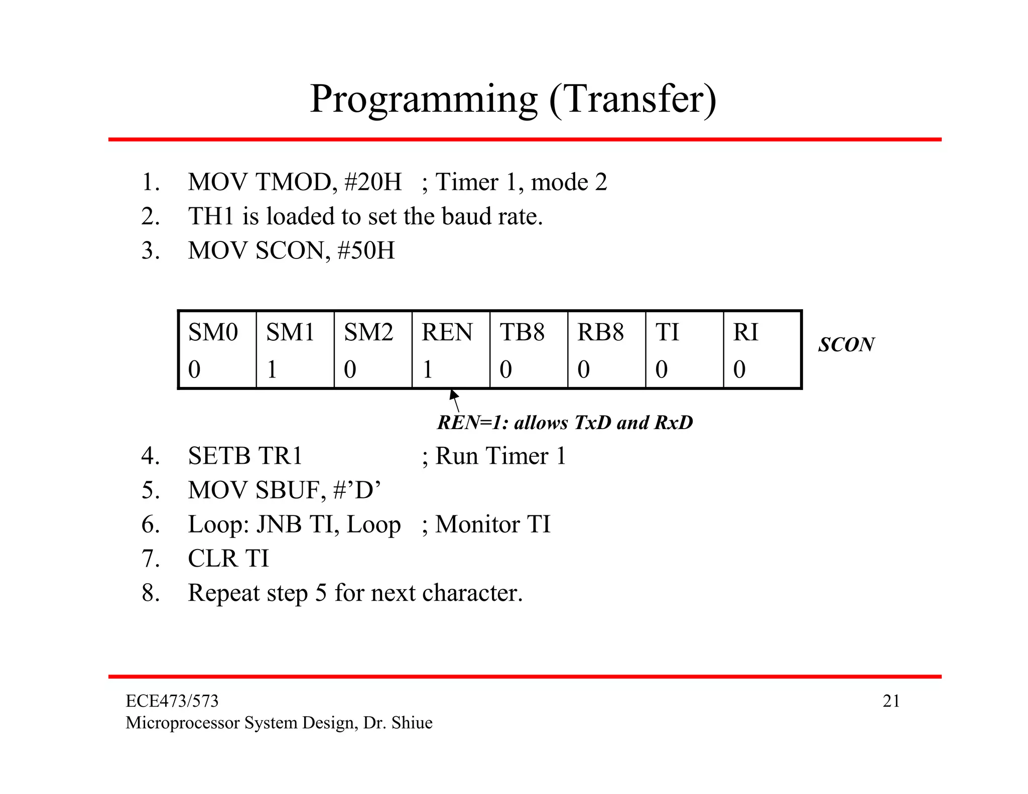
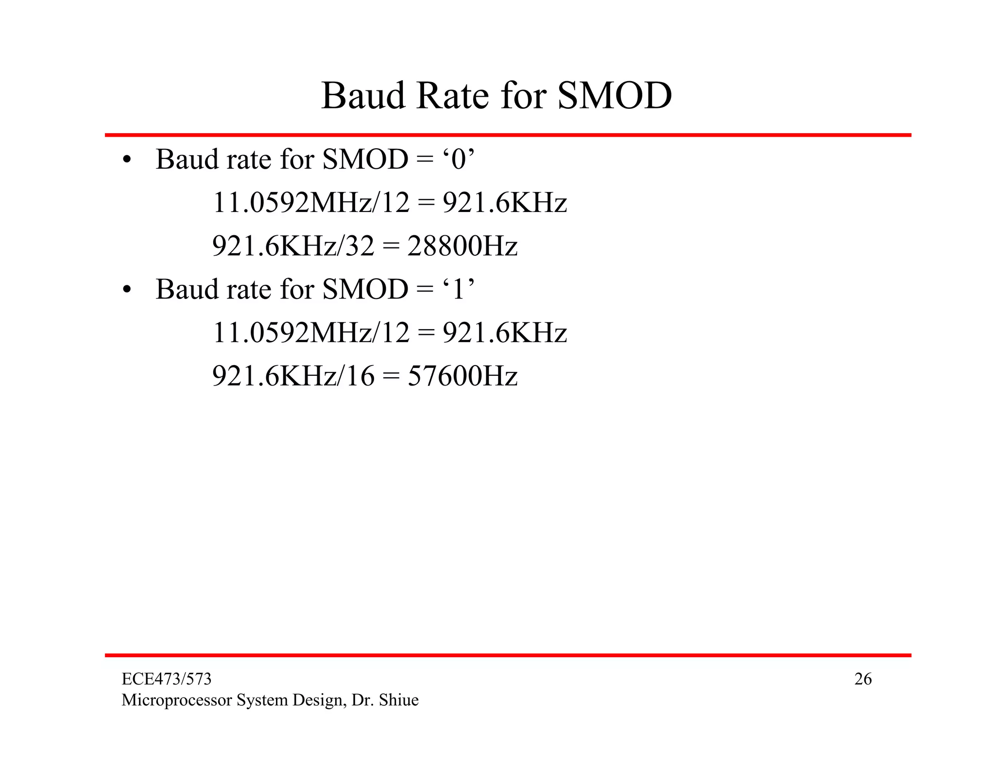
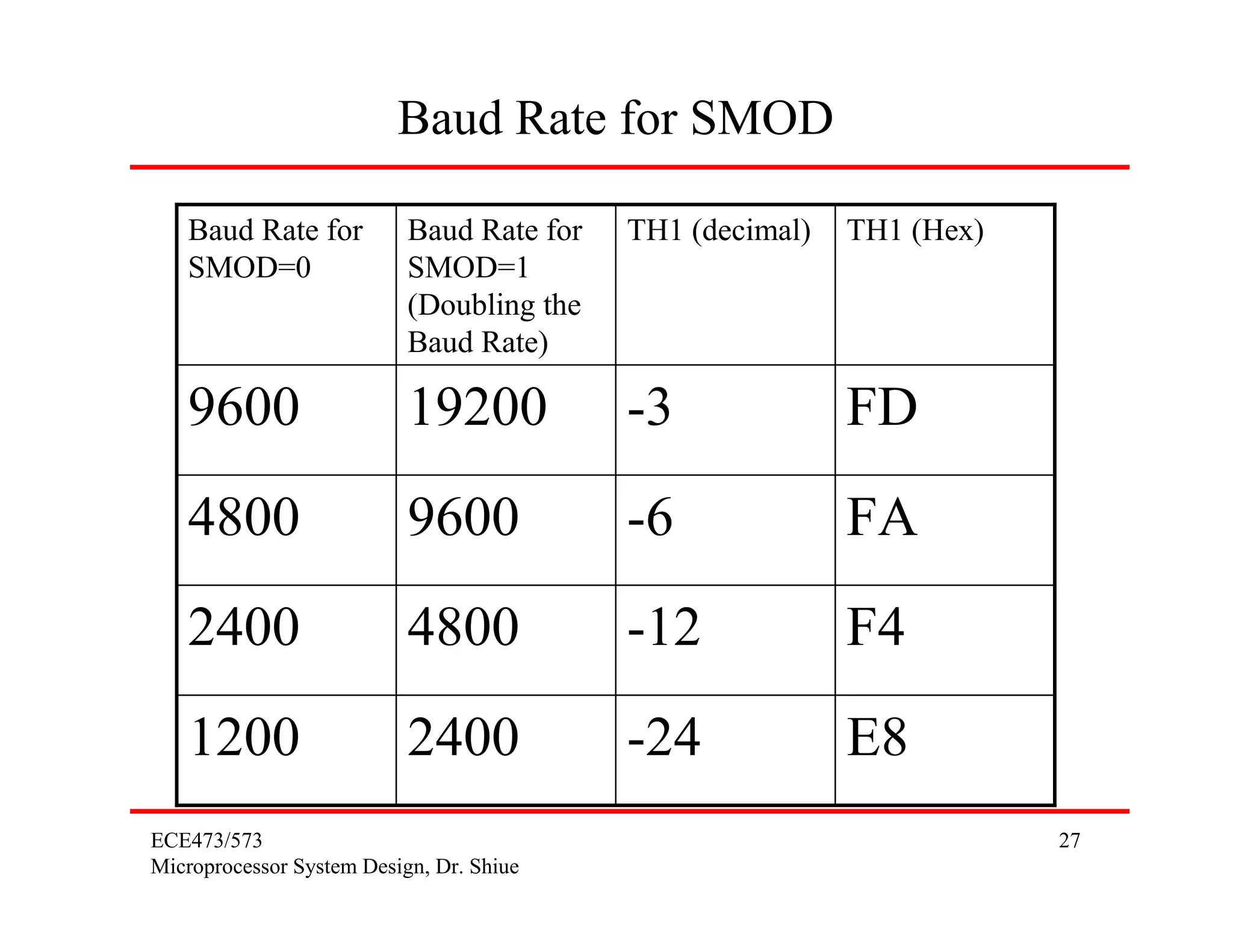
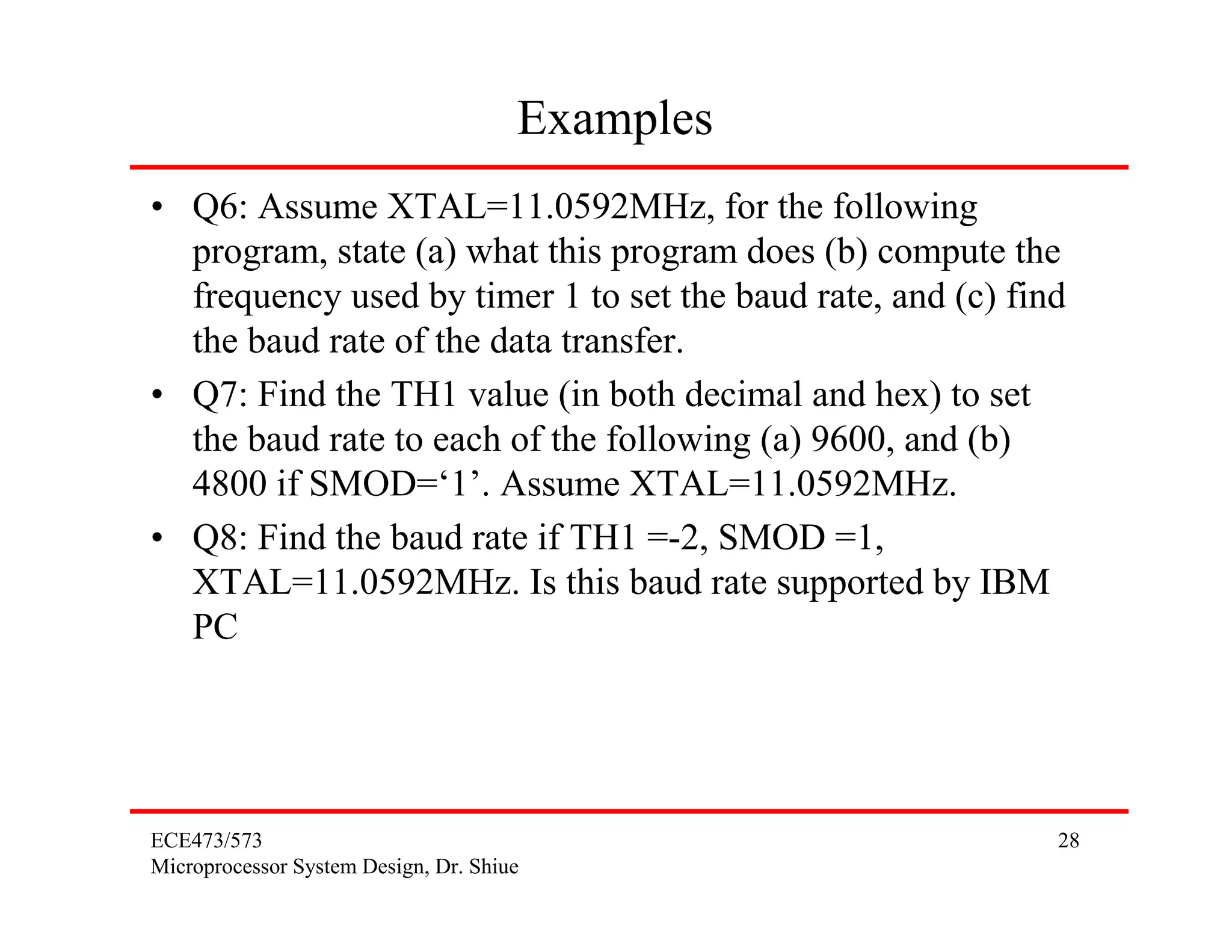
SlideShare a Scribd company logo
1 of 28
Download to read offline
8051 Serial Communications


ECE473/573                                1
Microprocessor System Design, Dr. Shiue
Parallel vs. Serial
• Parallel Communication (Printer)
     – Fast, but distance cannot be great.
                                               One byte at a time or more
     – Expensive
                                             Sender        Receiver


• Serial Communication (Telephone line)
     – Long distance
     – cheaper
                                    Sender     One bit/data line      Receiver
                                    City A                             City B


ECE473/573                                                                       2
Microprocessor System Design, Dr. Shiue
Serial Communications
•   Serial Communication (Telephone line)
•   P/S: Parallel-in-Serial-out Shift Register
•   S/P: Serial-in-Parallel-out Shift Register
•   D/A: Digital-Analog Converter
•   A/D: Analog-Digital Converter


        Sender                                            Receiver
                   P/S     D/A
                            D/A              A/D   D/A
                                                    S/P    City B
        City A


ECE473/573                                                           3
Microprocessor System Design, Dr. Shiue
Asynchronous vs. Synchronous
• Two methods of Serial Communication
     – Synchronous: Transfer block of data (characters) at a time.
     – Asynchronous: Transfer a single byte at a time.
• You could write S/W to use either of these methods, but
  the programs can be tedious and long. So, H/W is
  developed instead.
• This H/W is called UART or USART
• UART: Universal Asynchronous Receiver-Transmitter
• USART: Universal Synchronous-Asynchronous Receiver-
  Transmitter
• The 8051 chip has a built-in UART.


ECE473/573                                                           4
Microprocessor System Design, Dr. Shiue
Duplex vs. Simplex
• Duplex
                         PC                 Tx and Rx         PC


• Simplex (only transmit)


                                          Only Tx
                                    PC              Printer


ECE473/573                                                         5
Microprocessor System Design, Dr. Shiue
Duplex
• Full Duplex: Data is transmitted both way at the same
  time.

                         Tx                 Need 2 lines   Rx


                         Rx                                Tx


• Half Duplex: Data is transmitted one way at a time.

                         Tx                 Need 1 lines   Rx


                         Rx                                Tx


ECE473/573                                                      6
Microprocessor System Design, Dr. Shiue
Asynchronous Communications
• Asynchronous serial communication is widely used for
  character-oriented (1 byte) transmissions.
        – Synchronous serial communication is widely used for block-
          oriented (multiple bytes) transmissions.
• Start and stop bits
                                            Framing
                                          ASCII Character

         STOP       D7    D6      D5       D4     D3   D2   D1   D0    START mark
space     bit                                                            bit


         One or two bits ‘1’
                                                                  Only one bit ‘0’
         Go out last!
                                                                  Go out first!

ECE473/573                                                                           7
Microprocessor System Design, Dr. Shiue
Asynchronous
• New System: ASCII character A (0100 0001B)                                     8-bit
        – When there is no transfer, mark is ‘1’ and space is ‘0’.

Space    1       0      1        0        0      0      0    0   1           0       Mark
=0                                                                                   =1


• Older System: ASCII is 7-bit
        – Due to the slowness of receiving mechanical devices, 2 stop bits
          were used to give the device sufficient time to organize itself.

             2                       7-bit ASCII Character               1


           Stop bits                                                 Start bit


ECE473/573                                                                                  8
Microprocessor System Design, Dr. Shiue
Parity Bit
• Even-Parity bit system
     – 01001011            # of ‘1’=4        P=0
• Odd-Parity bit system
     – 01001011            # of ‘1’=4        P=1
• UART chips allow programming of the parity bit for odd-,
  even-, and no-parity options.


ECE473/573                                                   9
Microprocessor System Design, Dr. Shiue
Data Transfer Rate
• Data Transfer Rate
     – Bits per second (bps) is also called Baud rate (the number of
       signals changes per second)
     – IBM PC/XT        100 ~ 9600 bps
     – Pentium PC      56k bps (recent MODEM)
• Asynchronous data communication, the baud rate is
  limited to 100,000 bps.
• Interfacing standard: RS232


ECE473/573                                                             10
Microprocessor System Design, Dr. Shiue
RS232
• PC: COM1 (Mouse), COM2: (MODEM & RS232)
• RS232 is set by Electronics Industries Association (EIA) in
  1960.
• 1963: RS232A
• 1965: RS232B
• 1969: RS232C
• RS232 is a serial I/O interfacing standard; however, since
  the standard was set long before the advent of the TTL
  logic family, its input and output voltage levels are not
  TTL compatible.
• TTL is Transistor-Transistor Logic family (Bipolar
  transistor) in 1968


ECE473/573                                                 11
Microprocessor System Design, Dr. Shiue
Line Driver: MAX232
• RS232 is not compatible to TTL. For this reason, to
  connect any RS232 to a microcontroller system, we must
  use “Voltage Converters” such as MAX232 to convert the
  TTL logic levels to the RS232 voltage levels, and vice
  versa.
• MAX232 IC chips is referred to as “Line Driver”.


ECE473/573                                             12
Microprocessor System Design, Dr. Shiue
RS232 Connector: DB-25
• DB-25 Connector                         Pin 1: Ground
     – DB-25P (Plug)                      Pin 2: TxD
     – DB-25S (Socket)                    Pin 3: RxD
                                            :


                      1                                        13


                          14                              25


• DTE: Data Terminal Equipment: RS232
• DCE: Data Communication Equipment: MODEM
ECE473/573                                                          13
Microprocessor System Design, Dr. Shiue
RS232 Connector: DB-9
• DB-9 Connector

       Pin     function description
       1       !DCD          Data Carrier Detect
                                                   1        5
       2       RxD           Receive
                                                   6   9
       3       TxD           Transmit
       4       DTR           Data Terminal Ready
       5       GND           Ground
       6       !DSR          Data Set Ready
       7       !RTS          Request To Send
       8       !CTS          Clear To Send
       9       RI            Ring Indicator

ECE473/573                                             14
Microprocessor System Design, Dr. Shiue
8051 Connection to RS232
• Since RS232 standard is not TTL compatible, so we need
  MAX232 (line driver)


      8051


                                                 MAX232           DB-9 (RS232 Connector)

                          11 (P3.1)       11 T1 in    T1 out 14       2 RxD
                   TxD

                   RxD 10 (P3.0)          12 R1 out   R1 in 13       3 TxD

                                                                         5
                                                                       GND


ECE473/573                                                                         15
Microprocessor System Design, Dr. Shiue
Baud Rate
• Q1: With XTAL=11.0592MHz, find the TH1 value needed
  to have the following baud rate: (a) 9600, (b) 2400, and (c)
  1200.


ECE473/573                                                  16
Microprocessor System Design, Dr. Shiue
SBUF Register
• SBUF Register: For a byte of data to be transferred via the
  TxD line, it must be placed in the SBUF.
• SBUF holds the byte of data when it is received by the
  8051’s RxD line.

      8051


                             Framed              MAX232           DB-9 (RS232 Connector)

                          11 (P3.1)       11 T1 in    T1 out 14       2 RxD
                   TxD
       SBUF
                   RxD 10 (P3.0)          12 R1 out   R1 in 13       3 TxD

                             Deframed                                    5
                                                                       GND

ECE473/573                                                                         17
Microprocessor System Design, Dr. Shiue
SCON Register

     SM0       SM1       SM2       REN TB8          RB8     TI       RI   SCON

• Mode 0, 2, and 3 are ready used today.
• Mode 1 is compatible with the COM port of IBM PC.
• Mode 1 allows the baud rate to be variable and is set by
  Timer 1 of 8051.
       SM0 SM1 Mode
       0       0        0
       0       1        1          8 bit data, 1 stop bit , 1 start bit
       1       0        2
       1       1        3

ECE473/573                                                                   18
Microprocessor System Design, Dr. Shiue
SCON Register

   • SM2     enable the multiprocessing capability of the 8051.
     Here we make SM2=0.
   • REN: Receive Enable
        – REN=1: it allows the 8051 to receive data on the RxD pin. If you
          want the 8051 to both transfer and receive data, REN must be set
          to ‘1’. SETB SCON.4
        – REN=0: make the receiver is disabled.
   • TB8: Transfer bit 8
        – Is used for serial modes 2 and 3, so here we make TB8=0.

           Stop D7           D6       D5        D4      D3   D2   D1   D0
           Bit
Bit 8

                                           1 byte of data

 ECE473/573                                                                 19
 Microprocessor System Design, Dr. Shiue
SCON Register
 • RB8: Receive bit 8
       – Is used for serial modes 2 and 3, so here we make RB8=0.
 • TI: Transmit Interrupt (this is a flag bit)
       – When 8051 finish the transfer of the 8-bit character, it raises the TI
         flag to indicate that it is ready to transfer another byte.
 • RI: Receive Interrupt
       – When 8051 receive data via RxD, it get rid of the start and stop
         bits (deframed procedure) and places the byte in the SBUF.
       – Then it raises the RI flag to indicate that a byte has been received
         and should be picked up before it is lost.


ECE473/573                                                                  20
Microprocessor System Design, Dr. Shiue
Programming (Transfer)
 1.    MOV TMOD, #20H ; Timer 1, mode 2
 2.    TH1 is loaded to set the baud rate.
 3.    MOV SCON, #50H


       SM0       SM1       SM2       REN TB8           RB8     TI     RI   SCON
       0         1         0         1   0             0       0      0
                                          REN=1: allows TxD and RxD
 4.    SETB TR1               ; Run Timer 1
 5.    MOV SBUF, #’D’
 6.    Loop: JNB TI, Loop ; Monitor TI
 7.    CLR TI
 8.    Repeat step 5 for next character.


ECE473/573                                                                        21
Microprocessor System Design, Dr. Shiue
Examples
• Q2: Write a program for the 8051 to transfer letter ‘A’
  serially at 4800 baud rate, continuously.
• Q3: Write a program to transfer the message “Yes” serially
  at 9600 baud, do this continuously.


ECE473/573                                                22
Microprocessor System Design, Dr. Shiue
Programming (Receive)
 1.    MOV TMOD, #20H ; Timer 1, mode 2
 2.    TH1 is loaded to set the baud rate.
 3.    MOV SCON, #50H

       SM0       SM1       SM2       REN TB8           RB8     TI     RI   SCON
       0         1         0         1   0             0       0      0
                                          REN=1: allows TxD and RxD

 4.    SETB TR1               ; Run Timer 1
 5.    Loop: JNB RI, Loop ; Monitor RI
 6.    MOV A, SBUF
 7.    CLR RI
 8.    Repeat step 5 for next character.

ECE473/573                                                                        23
Microprocessor System Design, Dr. Shiue
Examples
• Q4: Program the 8051 to receive bytes of data serially, and
  put them in P1. Set the baud rate at 4800.
• Q5: Write a program to (a) send to the PC the message
  “We Are Ready”, (b) receive any data sent by the PC and
  put it ob LEDs connected to P1, and (c) get data on
  switches and sent it to PC. The program should perform
  part (a) once, but parts (b) and (c) continuously. Use the
  4800 baud rate.


ECE473/573                                                  24
Microprocessor System Design, Dr. Shiue
Doubling the Baud Rate
• Method 1: Use a high XTAL
     – This method is infeasible since XTAL is fixed.
     – If you change XTAL, and then it is not compatible to PC.
• Method 2: Change a bit in the PCON register

 SMOD       -          -         -        GF1   GF0   PD     IDL
                                                                   PCON


          Serial Mode Bit
• When 8051 is powered up, D7 of PCON =0, we could set D7 of PCON
  ‘1’ to double the baud rate.
• Note that PCON is not bit addressible, so we need to do the following
        MOV A, PCON
        SETB ACC.7
        MOV PCON, A

ECE473/573                                                                25
Microprocessor System Design, Dr. Shiue
Baud Rate for SMOD
• Baud rate for SMOD = ‘0’
      11.0592MHz/12 = 921.6KHz
      921.6KHz/32 = 28800Hz
• Baud rate for SMOD = ‘1’
      11.0592MHz/12 = 921.6KHz
      921.6KHz/16 = 57600Hz


ECE473/573                                     26
Microprocessor System Design, Dr. Shiue
Baud Rate for SMOD

   Baud Rate for           Baud Rate for   TH1 (decimal)   TH1 (Hex)
   SMOD=0                  SMOD=1
                           (Doubling the
                           Baud Rate)

   9600                    19200           -3              FD
   4800                    9600            -6              FA
   2400                    4800            -12             F4
   1200                    2400            -24             E8
ECE473/573                                                             27
Microprocessor System Design, Dr. Shiue
Examples
• Q6: Assume XTAL=11.0592MHz, for the following
  program, state (a) what this program does (b) compute the
  frequency used by timer 1 to set the baud rate, and (c) find
  the baud rate of the data transfer.
• Q7: Find the TH1 value (in both decimal and hex) to set
  the baud rate to each of the following (a) 9600, and (b)
  4800 if SMOD=‘1’. Assume XTAL=11.0592MHz.
• Q8: Find the baud rate if TH1 =-2, SMOD =1,
  XTAL=11.0592MHz. Is this baud rate supported by IBM
  PC


ECE473/573                                                   28
Microprocessor System Design, Dr. Shiue

More Related Content

What's hot

UART(universal asynchronous receiver transmitter ) PPT
UART(universal asynchronous receiver transmitter ) PPTUART(universal asynchronous receiver transmitter ) PPT
UART(universal asynchronous receiver transmitter ) PPTSai_praneeth
 
Serial Peripheral Interface(SPI)
Serial Peripheral Interface(SPI)Serial Peripheral Interface(SPI)
Serial Peripheral Interface(SPI)Dhaval Kaneria
 
I/O port programming in 8051
I/O port programming in 8051I/O port programming in 8051
I/O port programming in 8051ssuser3a47cb
 
Pic microcontroller architecture
Pic microcontroller architecturePic microcontroller architecture
Pic microcontroller architectureDominicHendry
 
8086 pin diagram description
8086 pin diagram description8086 pin diagram description
8086 pin diagram descriptionAkhil Singal
 
8051 Microcontroller I/O ports
8051 Microcontroller I/O ports8051 Microcontroller I/O ports
8051 Microcontroller I/O portsanishgoel
 
Introduction to arm architecture
Introduction to arm architectureIntroduction to arm architecture
Introduction to arm architectureZakaria Gomaa
 
8259 Programmable Interrupt Controller
8259 Programmable Interrupt Controller8259 Programmable Interrupt Controller
8259 Programmable Interrupt Controllerabhikalmegh
 
I2c protocol - Inter–Integrated Circuit Communication Protocol
I2c protocol - Inter–Integrated Circuit Communication ProtocolI2c protocol - Inter–Integrated Circuit Communication Protocol
I2c protocol - Inter–Integrated Circuit Communication ProtocolAnkur Soni
 
8257 DMA Controller
8257 DMA Controller8257 DMA Controller
8257 DMA ControllerShivamSood22
 
Programmableperipheralinterface 8255 ppt
Programmableperipheralinterface 8255 pptProgrammableperipheralinterface 8255 ppt
Programmableperipheralinterface 8255 pptsharan Kumar
 

What's hot (20)

SPI Bus Protocol
SPI Bus ProtocolSPI Bus Protocol
SPI Bus Protocol
 
dual-port RAM (DPRAM)
dual-port RAM (DPRAM)dual-port RAM (DPRAM)
dual-port RAM (DPRAM)
 
UART(universal asynchronous receiver transmitter ) PPT
UART(universal asynchronous receiver transmitter ) PPTUART(universal asynchronous receiver transmitter ) PPT
UART(universal asynchronous receiver transmitter ) PPT
 
Serial Peripheral Interface(SPI)
Serial Peripheral Interface(SPI)Serial Peripheral Interface(SPI)
Serial Peripheral Interface(SPI)
 
LCD Interacing with 8051
LCD Interacing with 8051LCD Interacing with 8051
LCD Interacing with 8051
 
I/O port programming in 8051
I/O port programming in 8051I/O port programming in 8051
I/O port programming in 8051
 
Pic microcontroller architecture
Pic microcontroller architecturePic microcontroller architecture
Pic microcontroller architecture
 
Serial Communication in 8051
Serial Communication in 8051Serial Communication in 8051
Serial Communication in 8051
 
8051 ch9-950217
8051 ch9-9502178051 ch9-950217
8051 ch9-950217
 
ARM Architecture
ARM ArchitectureARM Architecture
ARM Architecture
 
8086 pin diagram description
8086 pin diagram description8086 pin diagram description
8086 pin diagram description
 
8051 Microcontroller I/O ports
8051 Microcontroller I/O ports8051 Microcontroller I/O ports
8051 Microcontroller I/O ports
 
I2C BUS PROTOCOL
I2C BUS PROTOCOLI2C BUS PROTOCOL
I2C BUS PROTOCOL
 
Introduction to arm architecture
Introduction to arm architectureIntroduction to arm architecture
Introduction to arm architecture
 
UART
UARTUART
UART
 
8259 Programmable Interrupt Controller
8259 Programmable Interrupt Controller8259 Programmable Interrupt Controller
8259 Programmable Interrupt Controller
 
8255 PPI
8255 PPI8255 PPI
8255 PPI
 
I2c protocol - Inter–Integrated Circuit Communication Protocol
I2c protocol - Inter–Integrated Circuit Communication ProtocolI2c protocol - Inter–Integrated Circuit Communication Protocol
I2c protocol - Inter–Integrated Circuit Communication Protocol
 
8257 DMA Controller
8257 DMA Controller8257 DMA Controller
8257 DMA Controller
 
Programmableperipheralinterface 8255 ppt
Programmableperipheralinterface 8255 pptProgrammableperipheralinterface 8255 ppt
Programmableperipheralinterface 8255 ppt
 

Viewers also liked

Applications of 8051 microcontrollers
Applications of 8051 microcontrollersApplications of 8051 microcontrollers
Applications of 8051 microcontrollersDr.YNM
 
Microprocessors and microcontrollers short answer questions and answers
Microprocessors and microcontrollers short answer questions and answersMicroprocessors and microcontrollers short answer questions and answers
Microprocessors and microcontrollers short answer questions and answersAbhijith Augustine
 
Electro magnetic interference and compatibility(ECM,ECI)
Electro magnetic interference and compatibility(ECM,ECI)Electro magnetic interference and compatibility(ECM,ECI)
Electro magnetic interference and compatibility(ECM,ECI)Palani murugan
 
Tower crane Basics
Tower crane BasicsTower crane Basics
Tower crane Basicsrama24x7
 
PLC, DCS and PLC vs DCS Presentation by Jitender Singh Shekhawat
PLC, DCS and PLC vs DCS Presentation by Jitender Singh ShekhawatPLC, DCS and PLC vs DCS Presentation by Jitender Singh Shekhawat
PLC, DCS and PLC vs DCS Presentation by Jitender Singh ShekhawatJitender Singh Shekhawat
 
DC GENERATOR CHARACTERISTICS
DC GENERATOR CHARACTERISTICSDC GENERATOR CHARACTERISTICS
DC GENERATOR CHARACTERISTICSRitabrata Roy
 
Ppt local tracking and gps
Ppt local tracking and gpsPpt local tracking and gps
Ppt local tracking and gpsmassab
 
CAN (Controller Area Network) Bus Protocol
CAN (Controller Area Network) Bus ProtocolCAN (Controller Area Network) Bus Protocol
CAN (Controller Area Network) Bus ProtocolAbhinaw Tiwari
 
Controller Area Network (Basic Level Presentation)
Controller Area Network (Basic Level Presentation)Controller Area Network (Basic Level Presentation)
Controller Area Network (Basic Level Presentation)Vikas Kumar
 
Automotive lighting - Led road lighting
Automotive lighting - Led road lightingAutomotive lighting - Led road lighting
Automotive lighting - Led road lightingCaner Göksel Sonuzun
 
cc tn aed aetc am&e p&p 2 tractors, farm equipments., ...
cc tn aed aetc am&e p&p 2 tractors, farm equipments., ...cc tn aed aetc am&e p&p 2 tractors, farm equipments., ...
cc tn aed aetc am&e p&p 2 tractors, farm equipments., ...Chidambaram Coomarasamy
 
Emi emc-pdf
Emi emc-pdfEmi emc-pdf
Emi emc-pdfnagastra
 
Serial Communication
Serial CommunicationSerial Communication
Serial CommunicationRashmi
 

Viewers also liked (20)

Applications of 8051 microcontrollers
Applications of 8051 microcontrollersApplications of 8051 microcontrollers
Applications of 8051 microcontrollers
 
Microprocessors and microcontrollers short answer questions and answers
Microprocessors and microcontrollers short answer questions and answersMicroprocessors and microcontrollers short answer questions and answers
Microprocessors and microcontrollers short answer questions and answers
 
Electro magnetic interference and compatibility(ECM,ECI)
Electro magnetic interference and compatibility(ECM,ECI)Electro magnetic interference and compatibility(ECM,ECI)
Electro magnetic interference and compatibility(ECM,ECI)
 
Tower crane Basics
Tower crane BasicsTower crane Basics
Tower crane Basics
 
DC GENERATOR
DC GENERATORDC GENERATOR
DC GENERATOR
 
Plc & scada report 6
Plc & scada report 6Plc & scada report 6
Plc & scada report 6
 
PLC, DCS and PLC vs DCS Presentation by Jitender Singh Shekhawat
PLC, DCS and PLC vs DCS Presentation by Jitender Singh ShekhawatPLC, DCS and PLC vs DCS Presentation by Jitender Singh Shekhawat
PLC, DCS and PLC vs DCS Presentation by Jitender Singh Shekhawat
 
DC GENERATOR CHARACTERISTICS
DC GENERATOR CHARACTERISTICSDC GENERATOR CHARACTERISTICS
DC GENERATOR CHARACTERISTICS
 
Ppt local tracking and gps
Ppt local tracking and gpsPpt local tracking and gps
Ppt local tracking and gps
 
Embedded Systems in Automotive
Embedded Systems in Automotive Embedded Systems in Automotive
Embedded Systems in Automotive
 
CAN (Controller Area Network) Bus Protocol
CAN (Controller Area Network) Bus ProtocolCAN (Controller Area Network) Bus Protocol
CAN (Controller Area Network) Bus Protocol
 
Controller Area Network (Basic Level Presentation)
Controller Area Network (Basic Level Presentation)Controller Area Network (Basic Level Presentation)
Controller Area Network (Basic Level Presentation)
 
Cranes ppt
Cranes pptCranes ppt
Cranes ppt
 
Automotive lighting - Led road lighting
Automotive lighting - Led road lightingAutomotive lighting - Led road lighting
Automotive lighting - Led road lighting
 
cc tn aed aetc am&e p&p 2 tractors, farm equipments., ...
cc tn aed aetc am&e p&p 2 tractors, farm equipments., ...cc tn aed aetc am&e p&p 2 tractors, farm equipments., ...
cc tn aed aetc am&e p&p 2 tractors, farm equipments., ...
 
Emi emc-pdf
Emi emc-pdfEmi emc-pdf
Emi emc-pdf
 
Serial Communication
Serial CommunicationSerial Communication
Serial Communication
 
GPS ppt.
GPS ppt. GPS ppt.
GPS ppt.
 
Rtos Concepts
Rtos ConceptsRtos Concepts
Rtos Concepts
 
DCS Or PLC
DCS Or PLCDCS Or PLC
DCS Or PLC
 

Similar to 8051 serial communication

8051 serial communication
8051 serial communication8051 serial communication
8051 serial communicationcanh phan
 
CS553_ST7_Ch06-DigitalDataComm.ppt
CS553_ST7_Ch06-DigitalDataComm.pptCS553_ST7_Ch06-DigitalDataComm.ppt
CS553_ST7_Ch06-DigitalDataComm.pptAnandaSaikia1
 
serial_busses_i2c.pptx
serial_busses_i2c.pptxserial_busses_i2c.pptx
serial_busses_i2c.pptxSKUP1
 
Microcontroller.pptx
Microcontroller.pptxMicrocontroller.pptx
Microcontroller.pptxSaba651353
 
ASTROSAT SSR - 2015-05-15
ASTROSAT SSR - 2015-05-15ASTROSAT SSR - 2015-05-15
ASTROSAT SSR - 2015-05-15Aritra Sarkar
 
The presentation is about USART and serial communication
The presentation is about USART and serial communicationThe presentation is about USART and serial communication
The presentation is about USART and serial communicationsinaankhalil
 
Serial Data Communication
Serial Data CommunicationSerial Data Communication
Serial Data CommunicationDesty Rahayu
 
Mp So C 18 Apr
Mp So C 18 AprMp So C 18 Apr
Mp So C 18 AprFNian
 
A guide to common automation terms
A guide to common automation termsA guide to common automation terms
A guide to common automation termsPratap Chandra
 
lecture_I2C_SPI.pptx
lecture_I2C_SPI.pptxlecture_I2C_SPI.pptx
lecture_I2C_SPI.pptxreemasajin1
 

Similar to 8051 serial communication (20)

8051 serial communication
8051 serial communication8051 serial communication
8051 serial communication
 
serial.ppt
serial.pptserial.ppt
serial.ppt
 
serial.ppt
serial.pptserial.ppt
serial.ppt
 
CS553_ST7_Ch06-DigitalDataComm.ppt
CS553_ST7_Ch06-DigitalDataComm.pptCS553_ST7_Ch06-DigitalDataComm.ppt
CS553_ST7_Ch06-DigitalDataComm.ppt
 
Serial Busses.pptx
Serial Busses.pptxSerial Busses.pptx
Serial Busses.pptx
 
serial_busses_i2c.pptx
serial_busses_i2c.pptxserial_busses_i2c.pptx
serial_busses_i2c.pptx
 
Microcontroller.pptx
Microcontroller.pptxMicrocontroller.pptx
Microcontroller.pptx
 
Lec 5
Lec 5Lec 5
Lec 5
 
ASTROSAT SSR - 2015-05-15
ASTROSAT SSR - 2015-05-15ASTROSAT SSR - 2015-05-15
ASTROSAT SSR - 2015-05-15
 
The presentation is about USART and serial communication
The presentation is about USART and serial communicationThe presentation is about USART and serial communication
The presentation is about USART and serial communication
 
Uart
UartUart
Uart
 
Batch 25(a)
Batch 25(a)Batch 25(a)
Batch 25(a)
 
Serial Data Communication
Serial Data CommunicationSerial Data Communication
Serial Data Communication
 
Mp So C 18 Apr
Mp So C 18 AprMp So C 18 Apr
Mp So C 18 Apr
 
A guide to common automation terms
A guide to common automation termsA guide to common automation terms
A guide to common automation terms
 
11_interface.ppt
11_interface.ppt11_interface.ppt
11_interface.ppt
 
lecture_I2C_SPI.pptx
lecture_I2C_SPI.pptxlecture_I2C_SPI.pptx
lecture_I2C_SPI.pptx
 
Networking concepts
Networking conceptsNetworking concepts
Networking concepts
 
Fingerprint Biometrics
Fingerprint BiometricsFingerprint Biometrics
Fingerprint Biometrics
 
Ppt seminar noc
Ppt seminar nocPpt seminar noc
Ppt seminar noc
 

Recently uploaded

Tampa BSides - Chef's Tour of Microsoft Security Adoption Framework (SAF)
Tampa BSides - Chef's Tour of Microsoft Security Adoption Framework (SAF)Tampa BSides - Chef's Tour of Microsoft Security Adoption Framework (SAF)
Tampa BSides - Chef's Tour of Microsoft Security Adoption Framework (SAF)Mark Simos
 
SAP Build Work Zone - Overview L2-L3.pptx
SAP Build Work Zone - Overview L2-L3.pptxSAP Build Work Zone - Overview L2-L3.pptx
SAP Build Work Zone - Overview L2-L3.pptxNavinnSomaal
 
Artificial intelligence in cctv survelliance.pptx
Artificial intelligence in cctv survelliance.pptxArtificial intelligence in cctv survelliance.pptx
Artificial intelligence in cctv survelliance.pptxhariprasad279825
 
From Family Reminiscence to Scholarly Archive .
From Family Reminiscence to Scholarly Archive .From Family Reminiscence to Scholarly Archive .
From Family Reminiscence to Scholarly Archive .Alan Dix
 
Designing IA for AI - Information Architecture Conference 2024
Designing IA for AI - Information Architecture Conference 2024Designing IA for AI - Information Architecture Conference 2024
Designing IA for AI - Information Architecture Conference 2024Enterprise Knowledge
 
Dev Dives: Streamline document processing with UiPath Studio Web
Dev Dives: Streamline document processing with UiPath Studio WebDev Dives: Streamline document processing with UiPath Studio Web
Dev Dives: Streamline document processing with UiPath Studio WebUiPathCommunity
 
New from BookNet Canada for 2024: BNC CataList - Tech Forum 2024
New from BookNet Canada for 2024: BNC CataList - Tech Forum 2024New from BookNet Canada for 2024: BNC CataList - Tech Forum 2024
New from BookNet Canada for 2024: BNC CataList - Tech Forum 2024BookNet Canada
 
Advanced Computer Architecture – An Introduction
Advanced Computer Architecture – An IntroductionAdvanced Computer Architecture – An Introduction
Advanced Computer Architecture – An IntroductionDilum Bandara
 
Search Engine Optimization SEO PDF for 2024.pdf
Search Engine Optimization SEO PDF for 2024.pdfSearch Engine Optimization SEO PDF for 2024.pdf
Search Engine Optimization SEO PDF for 2024.pdfRankYa
 
H2O.ai CEO/Founder: Sri Ambati Keynote at Wells Fargo Day
H2O.ai CEO/Founder: Sri Ambati Keynote at Wells Fargo DayH2O.ai CEO/Founder: Sri Ambati Keynote at Wells Fargo Day
H2O.ai CEO/Founder: Sri Ambati Keynote at Wells Fargo DaySri Ambati
 
Hyperautomation and AI/ML: A Strategy for Digital Transformation Success.pdf
Hyperautomation and AI/ML: A Strategy for Digital Transformation Success.pdfHyperautomation and AI/ML: A Strategy for Digital Transformation Success.pdf
Hyperautomation and AI/ML: A Strategy for Digital Transformation Success.pdfPrecisely
 
Commit 2024 - Secret Management made easy
Commit 2024 - Secret Management made easyCommit 2024 - Secret Management made easy
Commit 2024 - Secret Management made easyAlfredo García Lavilla
 
Anypoint Exchange: It’s Not Just a Repo!
Anypoint Exchange: It’s Not Just a Repo!Anypoint Exchange: It’s Not Just a Repo!
Anypoint Exchange: It’s Not Just a Repo!Manik S Magar
 
Powerpoint exploring the locations used in television show Time Clash
Powerpoint exploring the locations used in television show Time ClashPowerpoint exploring the locations used in television show Time Clash
Powerpoint exploring the locations used in television show Time Clashcharlottematthew16
 
Unleash Your Potential - Namagunga Girls Coding Club
Unleash Your Potential - Namagunga Girls Coding ClubUnleash Your Potential - Namagunga Girls Coding Club
Unleash Your Potential - Namagunga Girls Coding ClubKalema Edgar
 
"Subclassing and Composition – A Pythonic Tour of Trade-Offs", Hynek Schlawack
"Subclassing and Composition – A Pythonic Tour of Trade-Offs", Hynek Schlawack"Subclassing and Composition – A Pythonic Tour of Trade-Offs", Hynek Schlawack
"Subclassing and Composition – A Pythonic Tour of Trade-Offs", Hynek SchlawackFwdays
 
"LLMs for Python Engineers: Advanced Data Analysis and Semantic Kernel",Oleks...
"LLMs for Python Engineers: Advanced Data Analysis and Semantic Kernel",Oleks..."LLMs for Python Engineers: Advanced Data Analysis and Semantic Kernel",Oleks...
"LLMs for Python Engineers: Advanced Data Analysis and Semantic Kernel",Oleks...Fwdays
 
Vertex AI Gemini Prompt Engineering Tips
Vertex AI Gemini Prompt Engineering TipsVertex AI Gemini Prompt Engineering Tips
Vertex AI Gemini Prompt Engineering TipsMiki Katsuragi
 
Advanced Test Driven-Development @ php[tek] 2024
Advanced Test Driven-Development @ php[tek] 2024Advanced Test Driven-Development @ php[tek] 2024
Advanced Test Driven-Development @ php[tek] 2024Scott Keck-Warren
 

Recently uploaded (20)

Tampa BSides - Chef's Tour of Microsoft Security Adoption Framework (SAF)
Tampa BSides - Chef's Tour of Microsoft Security Adoption Framework (SAF)Tampa BSides - Chef's Tour of Microsoft Security Adoption Framework (SAF)
Tampa BSides - Chef's Tour of Microsoft Security Adoption Framework (SAF)
 
SAP Build Work Zone - Overview L2-L3.pptx
SAP Build Work Zone - Overview L2-L3.pptxSAP Build Work Zone - Overview L2-L3.pptx
SAP Build Work Zone - Overview L2-L3.pptx
 
Artificial intelligence in cctv survelliance.pptx
Artificial intelligence in cctv survelliance.pptxArtificial intelligence in cctv survelliance.pptx
Artificial intelligence in cctv survelliance.pptx
 
From Family Reminiscence to Scholarly Archive .
From Family Reminiscence to Scholarly Archive .From Family Reminiscence to Scholarly Archive .
From Family Reminiscence to Scholarly Archive .
 
Designing IA for AI - Information Architecture Conference 2024
Designing IA for AI - Information Architecture Conference 2024Designing IA for AI - Information Architecture Conference 2024
Designing IA for AI - Information Architecture Conference 2024
 
Dev Dives: Streamline document processing with UiPath Studio Web
Dev Dives: Streamline document processing with UiPath Studio WebDev Dives: Streamline document processing with UiPath Studio Web
Dev Dives: Streamline document processing with UiPath Studio Web
 
New from BookNet Canada for 2024: BNC CataList - Tech Forum 2024
New from BookNet Canada for 2024: BNC CataList - Tech Forum 2024New from BookNet Canada for 2024: BNC CataList - Tech Forum 2024
New from BookNet Canada for 2024: BNC CataList - Tech Forum 2024
 
Advanced Computer Architecture – An Introduction
Advanced Computer Architecture – An IntroductionAdvanced Computer Architecture – An Introduction
Advanced Computer Architecture – An Introduction
 
Search Engine Optimization SEO PDF for 2024.pdf
Search Engine Optimization SEO PDF for 2024.pdfSearch Engine Optimization SEO PDF for 2024.pdf
Search Engine Optimization SEO PDF for 2024.pdf
 
H2O.ai CEO/Founder: Sri Ambati Keynote at Wells Fargo Day
H2O.ai CEO/Founder: Sri Ambati Keynote at Wells Fargo DayH2O.ai CEO/Founder: Sri Ambati Keynote at Wells Fargo Day
H2O.ai CEO/Founder: Sri Ambati Keynote at Wells Fargo Day
 
Hyperautomation and AI/ML: A Strategy for Digital Transformation Success.pdf
Hyperautomation and AI/ML: A Strategy for Digital Transformation Success.pdfHyperautomation and AI/ML: A Strategy for Digital Transformation Success.pdf
Hyperautomation and AI/ML: A Strategy for Digital Transformation Success.pdf
 
Commit 2024 - Secret Management made easy
Commit 2024 - Secret Management made easyCommit 2024 - Secret Management made easy
Commit 2024 - Secret Management made easy
 
Anypoint Exchange: It’s Not Just a Repo!
Anypoint Exchange: It’s Not Just a Repo!Anypoint Exchange: It’s Not Just a Repo!
Anypoint Exchange: It’s Not Just a Repo!
 
Powerpoint exploring the locations used in television show Time Clash
Powerpoint exploring the locations used in television show Time ClashPowerpoint exploring the locations used in television show Time Clash
Powerpoint exploring the locations used in television show Time Clash
 
DMCC Future of Trade Web3 - Special Edition
DMCC Future of Trade Web3 - Special EditionDMCC Future of Trade Web3 - Special Edition
DMCC Future of Trade Web3 - Special Edition
 
Unleash Your Potential - Namagunga Girls Coding Club
Unleash Your Potential - Namagunga Girls Coding ClubUnleash Your Potential - Namagunga Girls Coding Club
Unleash Your Potential - Namagunga Girls Coding Club
 
"Subclassing and Composition – A Pythonic Tour of Trade-Offs", Hynek Schlawack
"Subclassing and Composition – A Pythonic Tour of Trade-Offs", Hynek Schlawack"Subclassing and Composition – A Pythonic Tour of Trade-Offs", Hynek Schlawack
"Subclassing and Composition – A Pythonic Tour of Trade-Offs", Hynek Schlawack
 
"LLMs for Python Engineers: Advanced Data Analysis and Semantic Kernel",Oleks...
"LLMs for Python Engineers: Advanced Data Analysis and Semantic Kernel",Oleks..."LLMs for Python Engineers: Advanced Data Analysis and Semantic Kernel",Oleks...
"LLMs for Python Engineers: Advanced Data Analysis and Semantic Kernel",Oleks...
 
Vertex AI Gemini Prompt Engineering Tips
Vertex AI Gemini Prompt Engineering TipsVertex AI Gemini Prompt Engineering Tips
Vertex AI Gemini Prompt Engineering Tips
 
Advanced Test Driven-Development @ php[tek] 2024
Advanced Test Driven-Development @ php[tek] 2024Advanced Test Driven-Development @ php[tek] 2024
Advanced Test Driven-Development @ php[tek] 2024
 

8051 serial communication

  • 1. 8051 Serial Communications ECE473/573 1 Microprocessor System Design, Dr. Shiue
  • 2. Parallel vs. Serial • Parallel Communication (Printer) – Fast, but distance cannot be great. One byte at a time or more – Expensive Sender Receiver • Serial Communication (Telephone line) – Long distance – cheaper Sender One bit/data line Receiver City A City B ECE473/573 2 Microprocessor System Design, Dr. Shiue
  • 3. Serial Communications • Serial Communication (Telephone line) • P/S: Parallel-in-Serial-out Shift Register • S/P: Serial-in-Parallel-out Shift Register • D/A: Digital-Analog Converter • A/D: Analog-Digital Converter Sender Receiver P/S D/A D/A A/D D/A S/P City B City A ECE473/573 3 Microprocessor System Design, Dr. Shiue
  • 4. Asynchronous vs. Synchronous • Two methods of Serial Communication – Synchronous: Transfer block of data (characters) at a time. – Asynchronous: Transfer a single byte at a time. • You could write S/W to use either of these methods, but the programs can be tedious and long. So, H/W is developed instead. • This H/W is called UART or USART • UART: Universal Asynchronous Receiver-Transmitter • USART: Universal Synchronous-Asynchronous Receiver- Transmitter • The 8051 chip has a built-in UART. ECE473/573 4 Microprocessor System Design, Dr. Shiue
  • 5. Duplex vs. Simplex • Duplex PC Tx and Rx PC • Simplex (only transmit) Only Tx PC Printer ECE473/573 5 Microprocessor System Design, Dr. Shiue
  • 6. Duplex • Full Duplex: Data is transmitted both way at the same time. Tx Need 2 lines Rx Rx Tx • Half Duplex: Data is transmitted one way at a time. Tx Need 1 lines Rx Rx Tx ECE473/573 6 Microprocessor System Design, Dr. Shiue
  • 7. Asynchronous Communications • Asynchronous serial communication is widely used for character-oriented (1 byte) transmissions. – Synchronous serial communication is widely used for block- oriented (multiple bytes) transmissions. • Start and stop bits Framing ASCII Character STOP D7 D6 D5 D4 D3 D2 D1 D0 START mark space bit bit One or two bits ‘1’ Only one bit ‘0’ Go out last! Go out first! ECE473/573 7 Microprocessor System Design, Dr. Shiue
  • 8. Asynchronous • New System: ASCII character A (0100 0001B) 8-bit – When there is no transfer, mark is ‘1’ and space is ‘0’. Space 1 0 1 0 0 0 0 0 1 0 Mark =0 =1 • Older System: ASCII is 7-bit – Due to the slowness of receiving mechanical devices, 2 stop bits were used to give the device sufficient time to organize itself. 2 7-bit ASCII Character 1 Stop bits Start bit ECE473/573 8 Microprocessor System Design, Dr. Shiue
  • 9. Parity Bit • Even-Parity bit system – 01001011 # of ‘1’=4 P=0 • Odd-Parity bit system – 01001011 # of ‘1’=4 P=1 • UART chips allow programming of the parity bit for odd-, even-, and no-parity options. ECE473/573 9 Microprocessor System Design, Dr. Shiue
  • 10. Data Transfer Rate • Data Transfer Rate – Bits per second (bps) is also called Baud rate (the number of signals changes per second) – IBM PC/XT 100 ~ 9600 bps – Pentium PC 56k bps (recent MODEM) • Asynchronous data communication, the baud rate is limited to 100,000 bps. • Interfacing standard: RS232 ECE473/573 10 Microprocessor System Design, Dr. Shiue
  • 11. RS232 • PC: COM1 (Mouse), COM2: (MODEM & RS232) • RS232 is set by Electronics Industries Association (EIA) in 1960. • 1963: RS232A • 1965: RS232B • 1969: RS232C • RS232 is a serial I/O interfacing standard; however, since the standard was set long before the advent of the TTL logic family, its input and output voltage levels are not TTL compatible. • TTL is Transistor-Transistor Logic family (Bipolar transistor) in 1968 ECE473/573 11 Microprocessor System Design, Dr. Shiue
  • 12. Line Driver: MAX232 • RS232 is not compatible to TTL. For this reason, to connect any RS232 to a microcontroller system, we must use “Voltage Converters” such as MAX232 to convert the TTL logic levels to the RS232 voltage levels, and vice versa. • MAX232 IC chips is referred to as “Line Driver”. ECE473/573 12 Microprocessor System Design, Dr. Shiue
  • 13. RS232 Connector: DB-25 • DB-25 Connector Pin 1: Ground – DB-25P (Plug) Pin 2: TxD – DB-25S (Socket) Pin 3: RxD : 1 13 14 25 • DTE: Data Terminal Equipment: RS232 • DCE: Data Communication Equipment: MODEM ECE473/573 13 Microprocessor System Design, Dr. Shiue
  • 14. RS232 Connector: DB-9 • DB-9 Connector Pin function description 1 !DCD Data Carrier Detect 1 5 2 RxD Receive 6 9 3 TxD Transmit 4 DTR Data Terminal Ready 5 GND Ground 6 !DSR Data Set Ready 7 !RTS Request To Send 8 !CTS Clear To Send 9 RI Ring Indicator ECE473/573 14 Microprocessor System Design, Dr. Shiue
  • 15. 8051 Connection to RS232 • Since RS232 standard is not TTL compatible, so we need MAX232 (line driver) 8051 MAX232 DB-9 (RS232 Connector) 11 (P3.1) 11 T1 in T1 out 14 2 RxD TxD RxD 10 (P3.0) 12 R1 out R1 in 13 3 TxD 5 GND ECE473/573 15 Microprocessor System Design, Dr. Shiue
  • 16. Baud Rate • Q1: With XTAL=11.0592MHz, find the TH1 value needed to have the following baud rate: (a) 9600, (b) 2400, and (c) 1200. ECE473/573 16 Microprocessor System Design, Dr. Shiue
  • 17. SBUF Register • SBUF Register: For a byte of data to be transferred via the TxD line, it must be placed in the SBUF. • SBUF holds the byte of data when it is received by the 8051’s RxD line. 8051 Framed MAX232 DB-9 (RS232 Connector) 11 (P3.1) 11 T1 in T1 out 14 2 RxD TxD SBUF RxD 10 (P3.0) 12 R1 out R1 in 13 3 TxD Deframed 5 GND ECE473/573 17 Microprocessor System Design, Dr. Shiue
  • 18. SCON Register SM0 SM1 SM2 REN TB8 RB8 TI RI SCON • Mode 0, 2, and 3 are ready used today. • Mode 1 is compatible with the COM port of IBM PC. • Mode 1 allows the baud rate to be variable and is set by Timer 1 of 8051. SM0 SM1 Mode 0 0 0 0 1 1 8 bit data, 1 stop bit , 1 start bit 1 0 2 1 1 3 ECE473/573 18 Microprocessor System Design, Dr. Shiue
  • 19. SCON Register • SM2 enable the multiprocessing capability of the 8051. Here we make SM2=0. • REN: Receive Enable – REN=1: it allows the 8051 to receive data on the RxD pin. If you want the 8051 to both transfer and receive data, REN must be set to ‘1’. SETB SCON.4 – REN=0: make the receiver is disabled. • TB8: Transfer bit 8 – Is used for serial modes 2 and 3, so here we make TB8=0. Stop D7 D6 D5 D4 D3 D2 D1 D0 Bit Bit 8 1 byte of data ECE473/573 19 Microprocessor System Design, Dr. Shiue
  • 20. SCON Register • RB8: Receive bit 8 – Is used for serial modes 2 and 3, so here we make RB8=0. • TI: Transmit Interrupt (this is a flag bit) – When 8051 finish the transfer of the 8-bit character, it raises the TI flag to indicate that it is ready to transfer another byte. • RI: Receive Interrupt – When 8051 receive data via RxD, it get rid of the start and stop bits (deframed procedure) and places the byte in the SBUF. – Then it raises the RI flag to indicate that a byte has been received and should be picked up before it is lost. ECE473/573 20 Microprocessor System Design, Dr. Shiue
  • 21. Programming (Transfer) 1. MOV TMOD, #20H ; Timer 1, mode 2 2. TH1 is loaded to set the baud rate. 3. MOV SCON, #50H SM0 SM1 SM2 REN TB8 RB8 TI RI SCON 0 1 0 1 0 0 0 0 REN=1: allows TxD and RxD 4. SETB TR1 ; Run Timer 1 5. MOV SBUF, #’D’ 6. Loop: JNB TI, Loop ; Monitor TI 7. CLR TI 8. Repeat step 5 for next character. ECE473/573 21 Microprocessor System Design, Dr. Shiue
  • 22. Examples • Q2: Write a program for the 8051 to transfer letter ‘A’ serially at 4800 baud rate, continuously. • Q3: Write a program to transfer the message “Yes” serially at 9600 baud, do this continuously. ECE473/573 22 Microprocessor System Design, Dr. Shiue
  • 23. Programming (Receive) 1. MOV TMOD, #20H ; Timer 1, mode 2 2. TH1 is loaded to set the baud rate. 3. MOV SCON, #50H SM0 SM1 SM2 REN TB8 RB8 TI RI SCON 0 1 0 1 0 0 0 0 REN=1: allows TxD and RxD 4. SETB TR1 ; Run Timer 1 5. Loop: JNB RI, Loop ; Monitor RI 6. MOV A, SBUF 7. CLR RI 8. Repeat step 5 for next character. ECE473/573 23 Microprocessor System Design, Dr. Shiue
  • 24. Examples • Q4: Program the 8051 to receive bytes of data serially, and put them in P1. Set the baud rate at 4800. • Q5: Write a program to (a) send to the PC the message “We Are Ready”, (b) receive any data sent by the PC and put it ob LEDs connected to P1, and (c) get data on switches and sent it to PC. The program should perform part (a) once, but parts (b) and (c) continuously. Use the 4800 baud rate. ECE473/573 24 Microprocessor System Design, Dr. Shiue
  • 25. Doubling the Baud Rate • Method 1: Use a high XTAL – This method is infeasible since XTAL is fixed. – If you change XTAL, and then it is not compatible to PC. • Method 2: Change a bit in the PCON register SMOD - - - GF1 GF0 PD IDL PCON Serial Mode Bit • When 8051 is powered up, D7 of PCON =0, we could set D7 of PCON ‘1’ to double the baud rate. • Note that PCON is not bit addressible, so we need to do the following MOV A, PCON SETB ACC.7 MOV PCON, A ECE473/573 25 Microprocessor System Design, Dr. Shiue
  • 26. Baud Rate for SMOD • Baud rate for SMOD = ‘0’ 11.0592MHz/12 = 921.6KHz 921.6KHz/32 = 28800Hz • Baud rate for SMOD = ‘1’ 11.0592MHz/12 = 921.6KHz 921.6KHz/16 = 57600Hz ECE473/573 26 Microprocessor System Design, Dr. Shiue
  • 27. Baud Rate for SMOD Baud Rate for Baud Rate for TH1 (decimal) TH1 (Hex) SMOD=0 SMOD=1 (Doubling the Baud Rate) 9600 19200 -3 FD 4800 9600 -6 FA 2400 4800 -12 F4 1200 2400 -24 E8 ECE473/573 27 Microprocessor System Design, Dr. Shiue
  • 28. Examples • Q6: Assume XTAL=11.0592MHz, for the following program, state (a) what this program does (b) compute the frequency used by timer 1 to set the baud rate, and (c) find the baud rate of the data transfer. • Q7: Find the TH1 value (in both decimal and hex) to set the baud rate to each of the following (a) 9600, and (b) 4800 if SMOD=‘1’. Assume XTAL=11.0592MHz. • Q8: Find the baud rate if TH1 =-2, SMOD =1, XTAL=11.0592MHz. Is this baud rate supported by IBM PC ECE473/573 28 Microprocessor System Design, Dr. Shiue