Downloaded 1,156 times
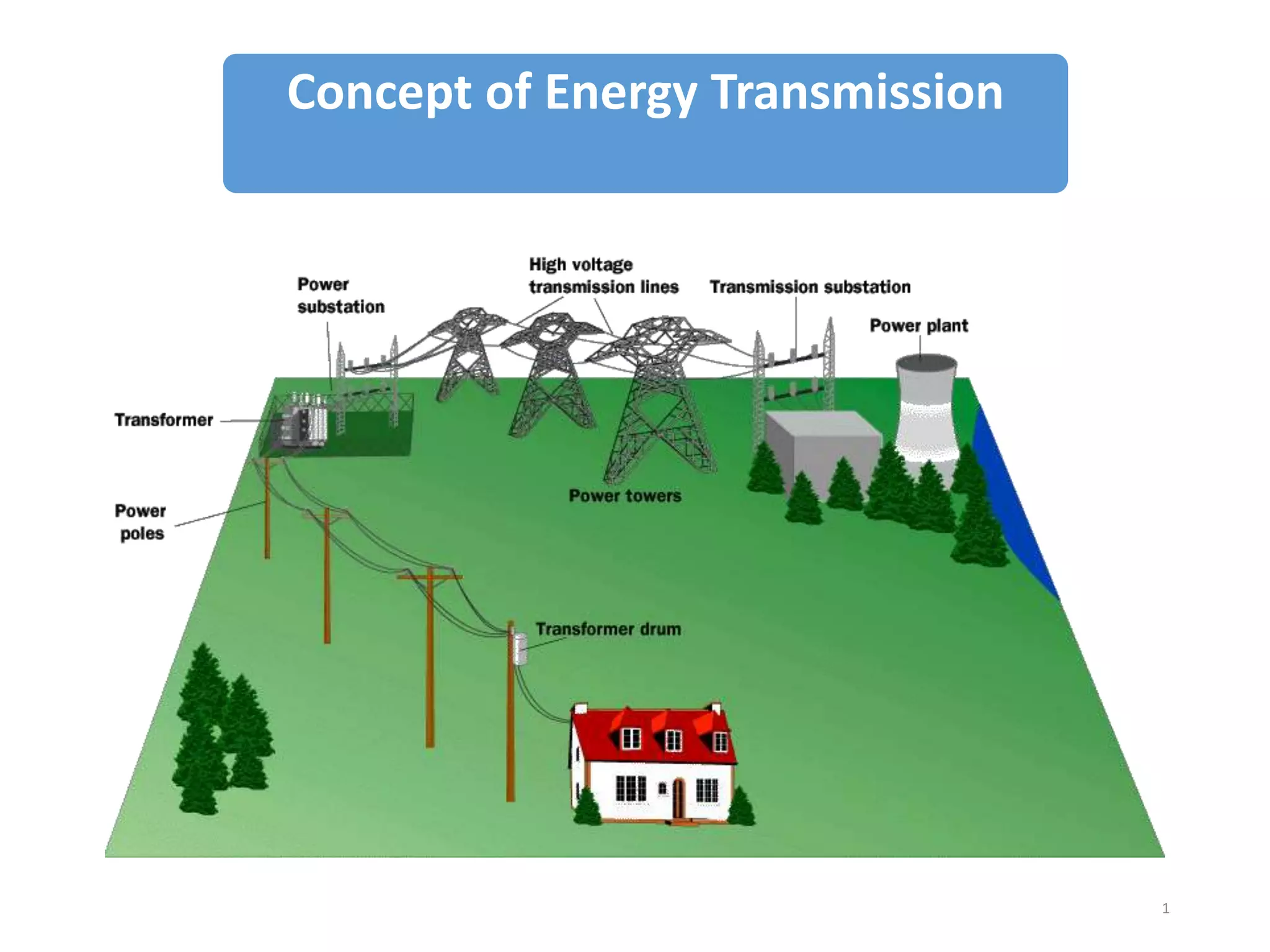
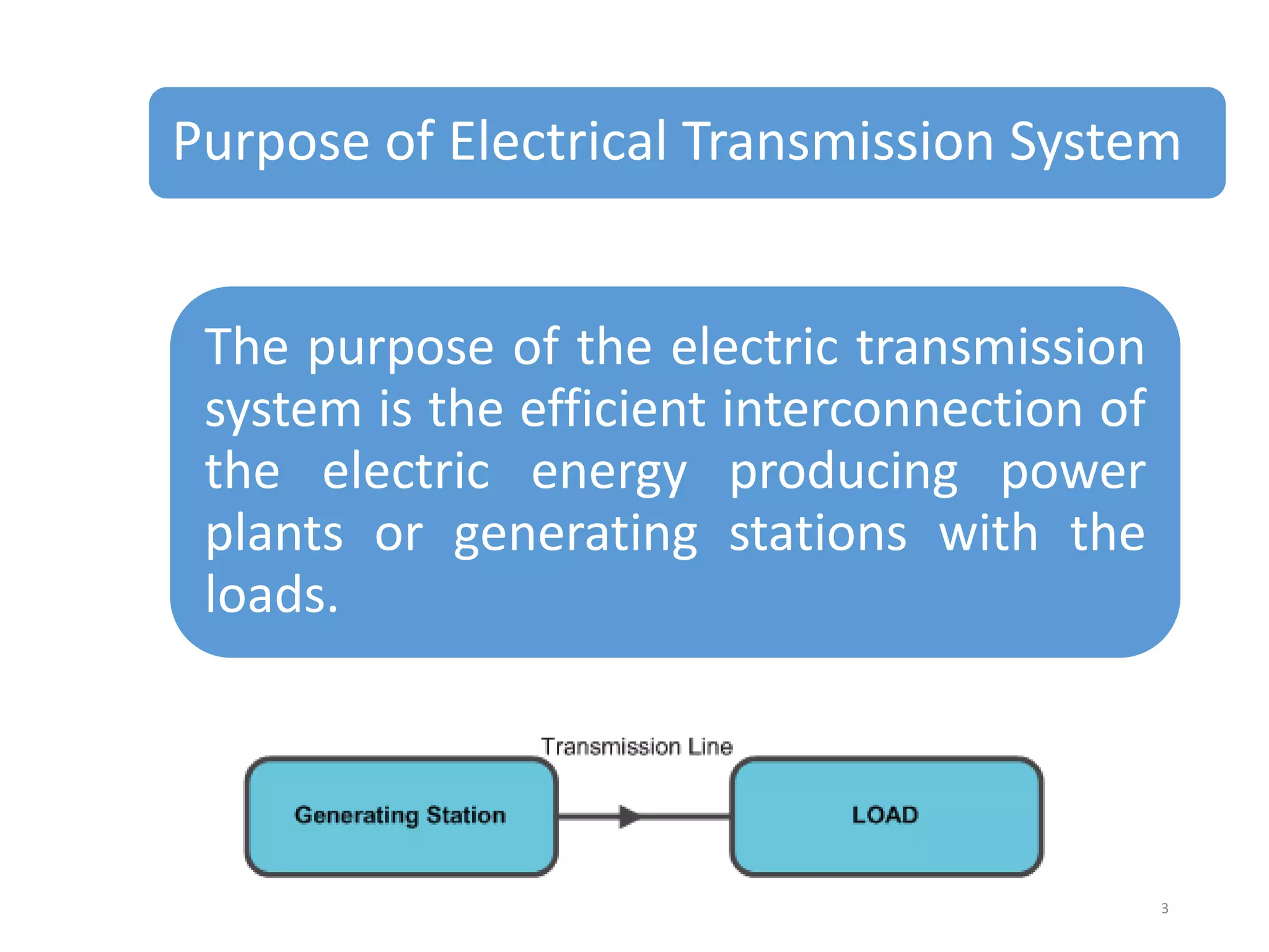
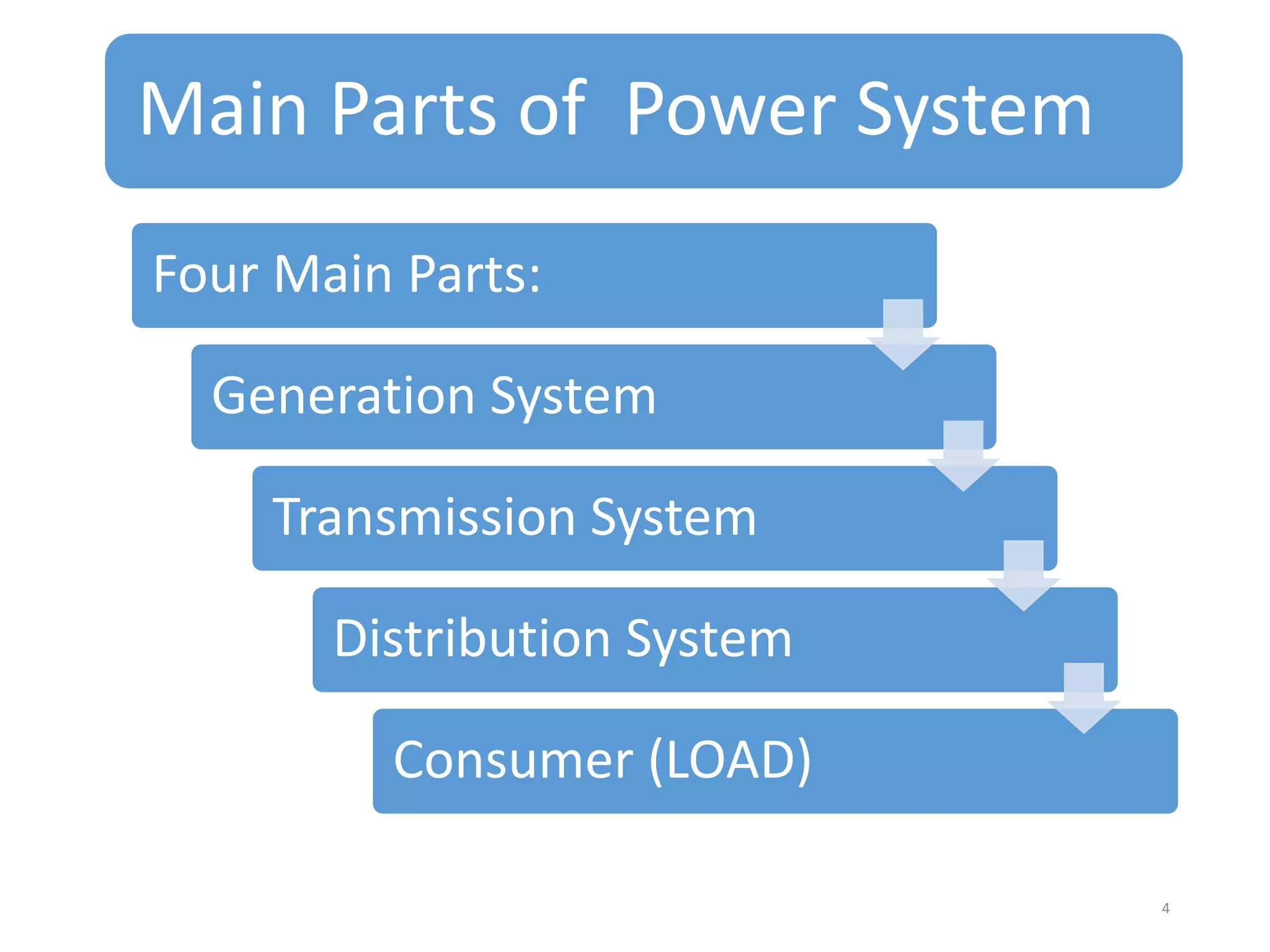
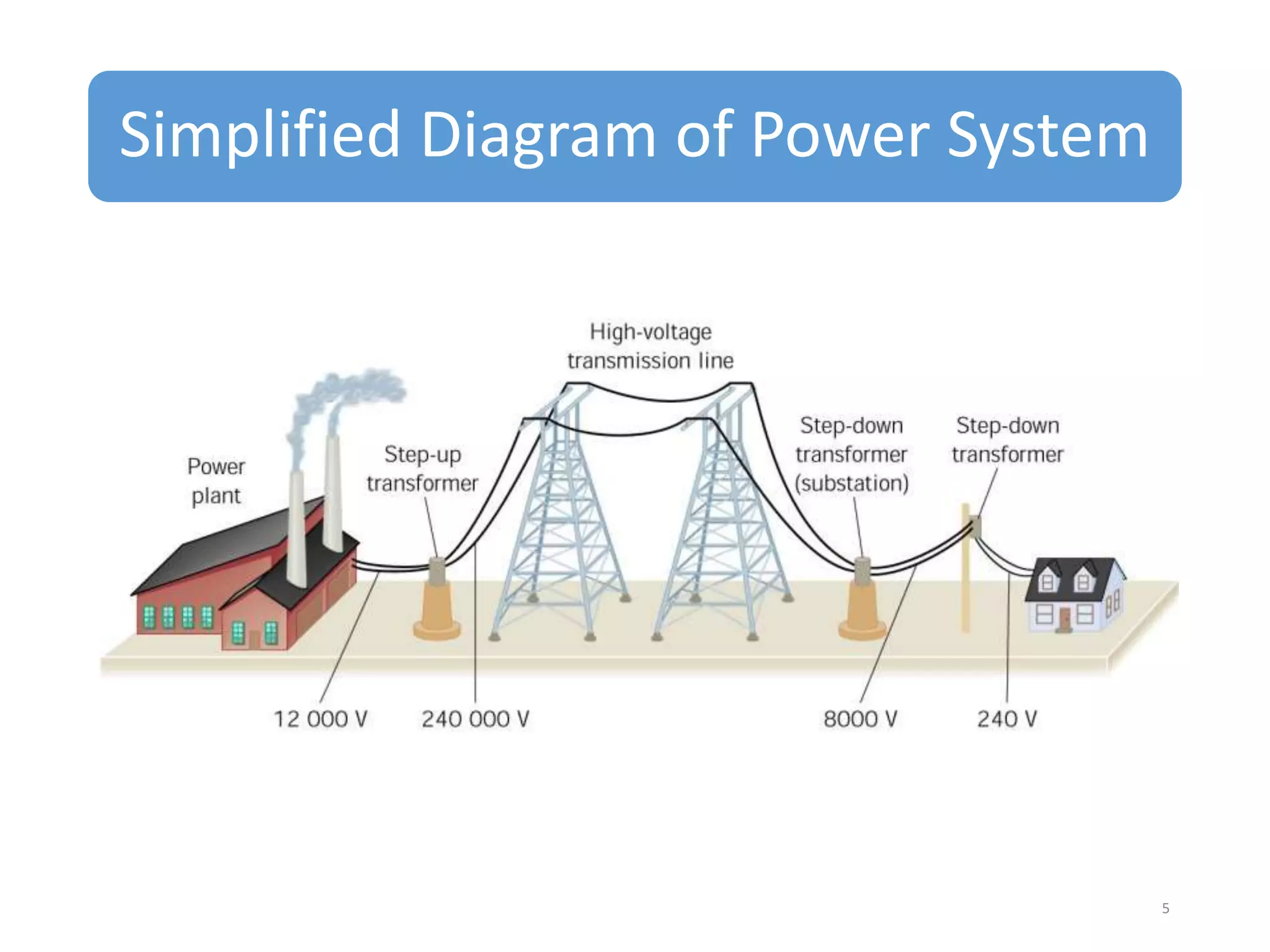
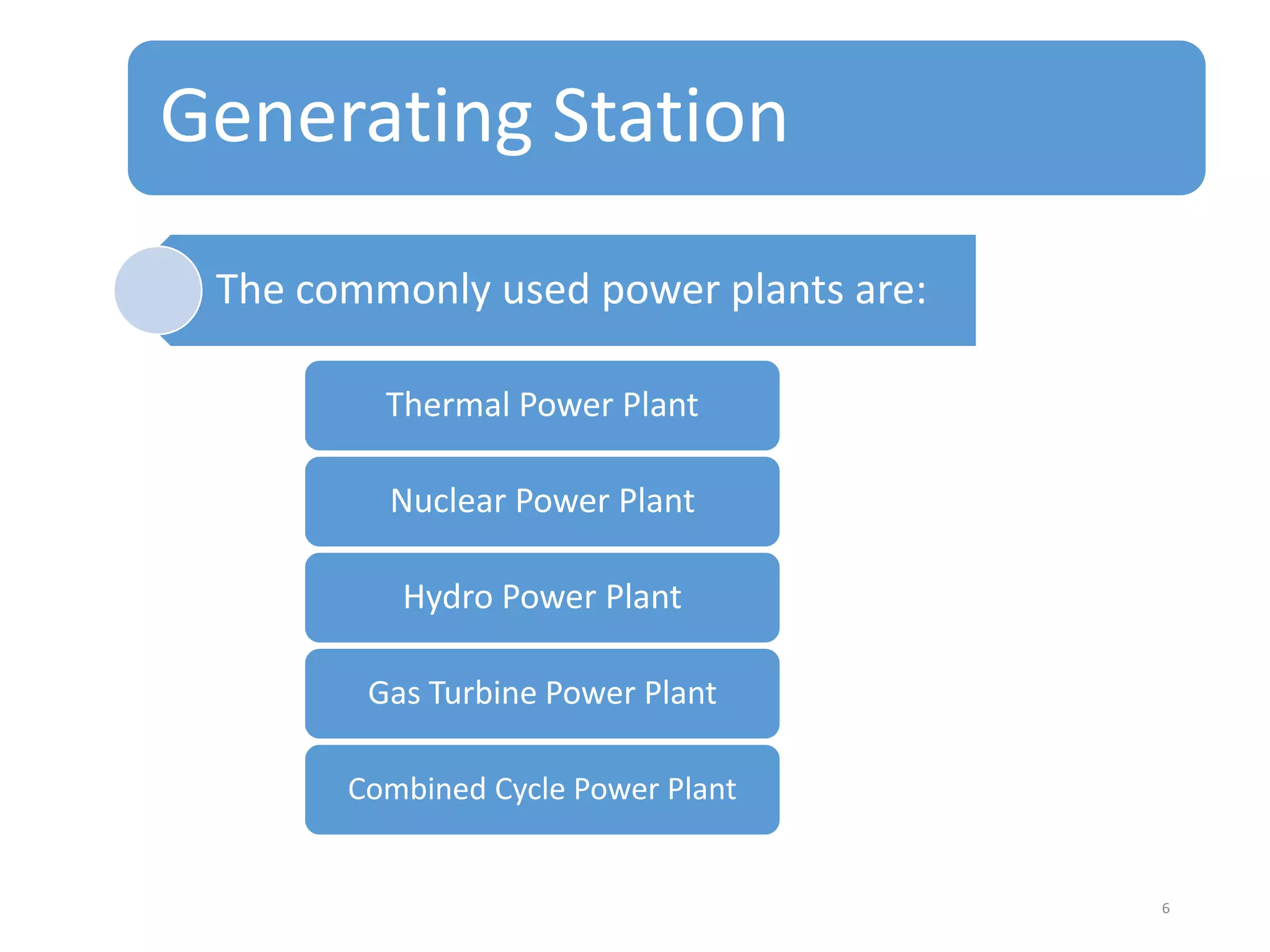
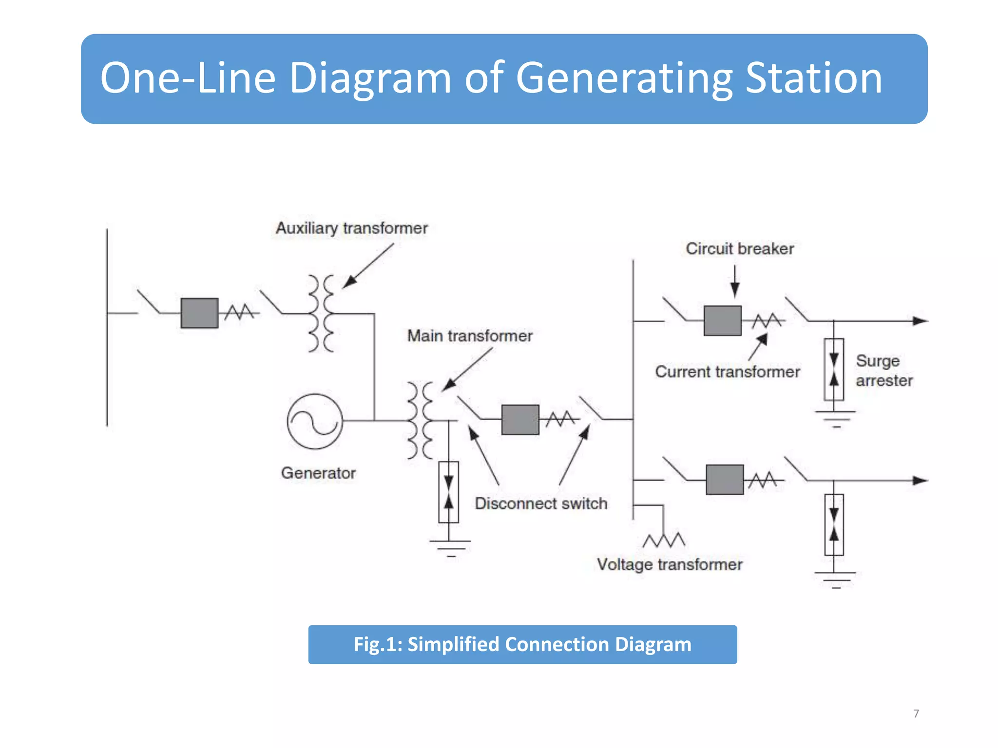
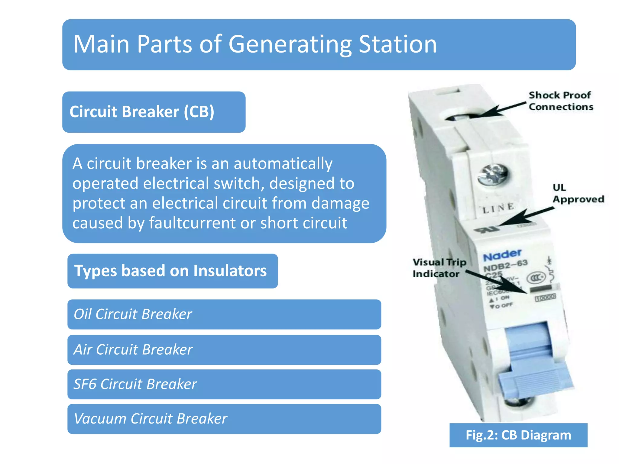
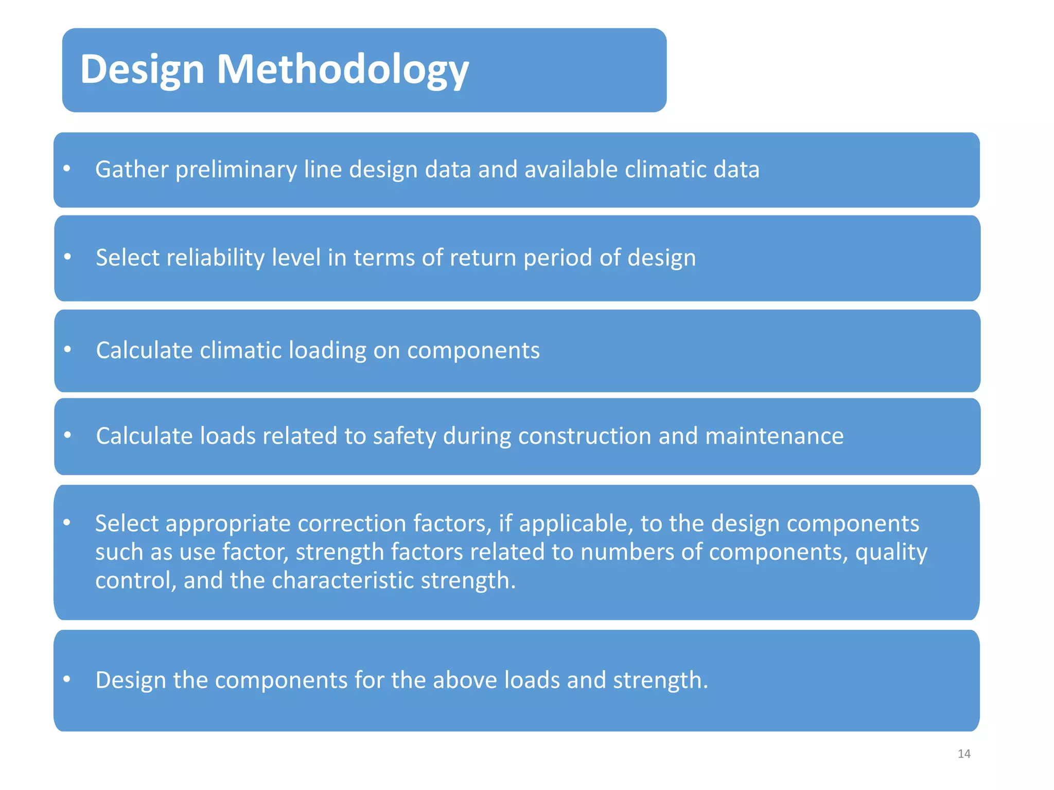
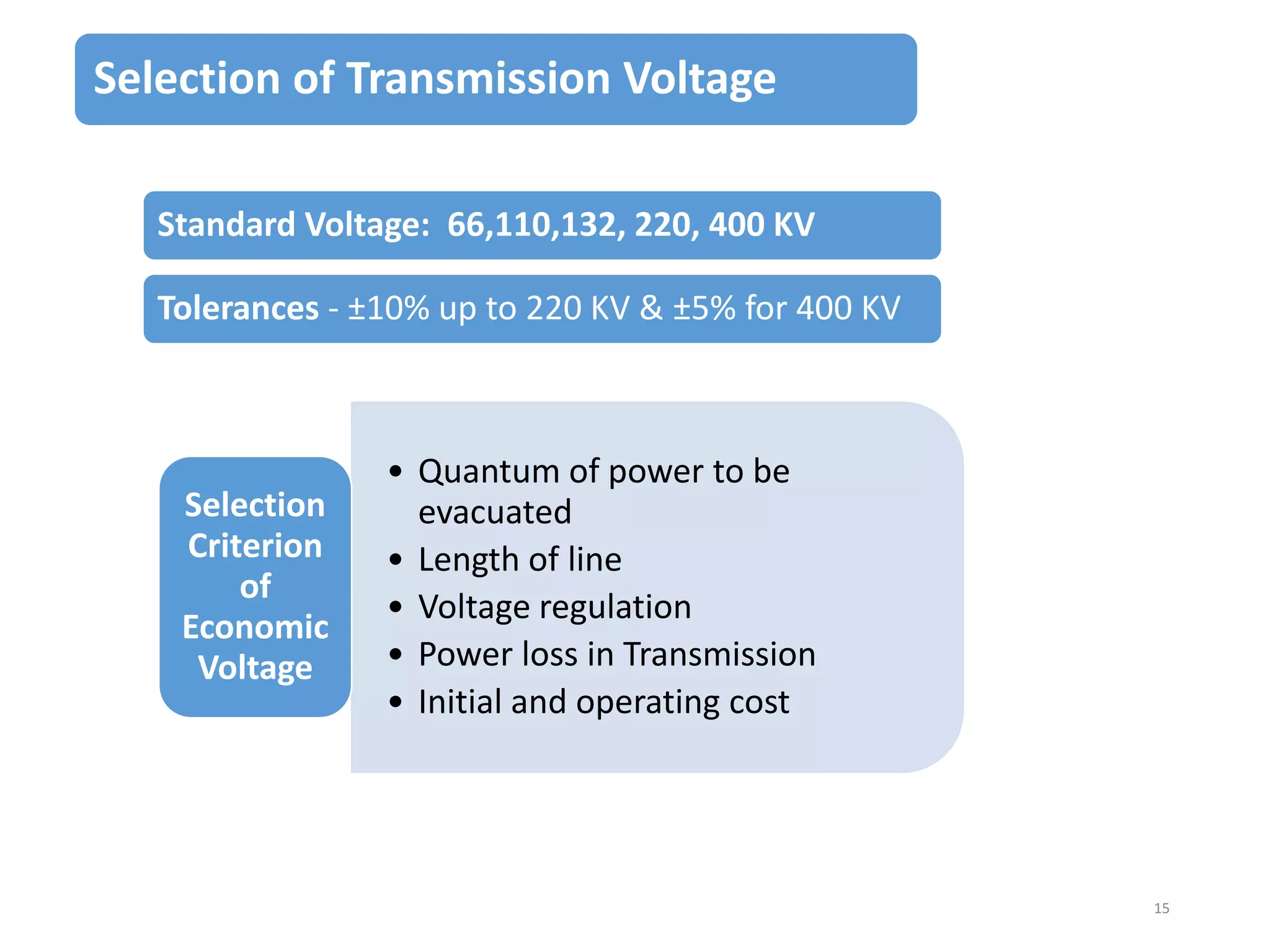
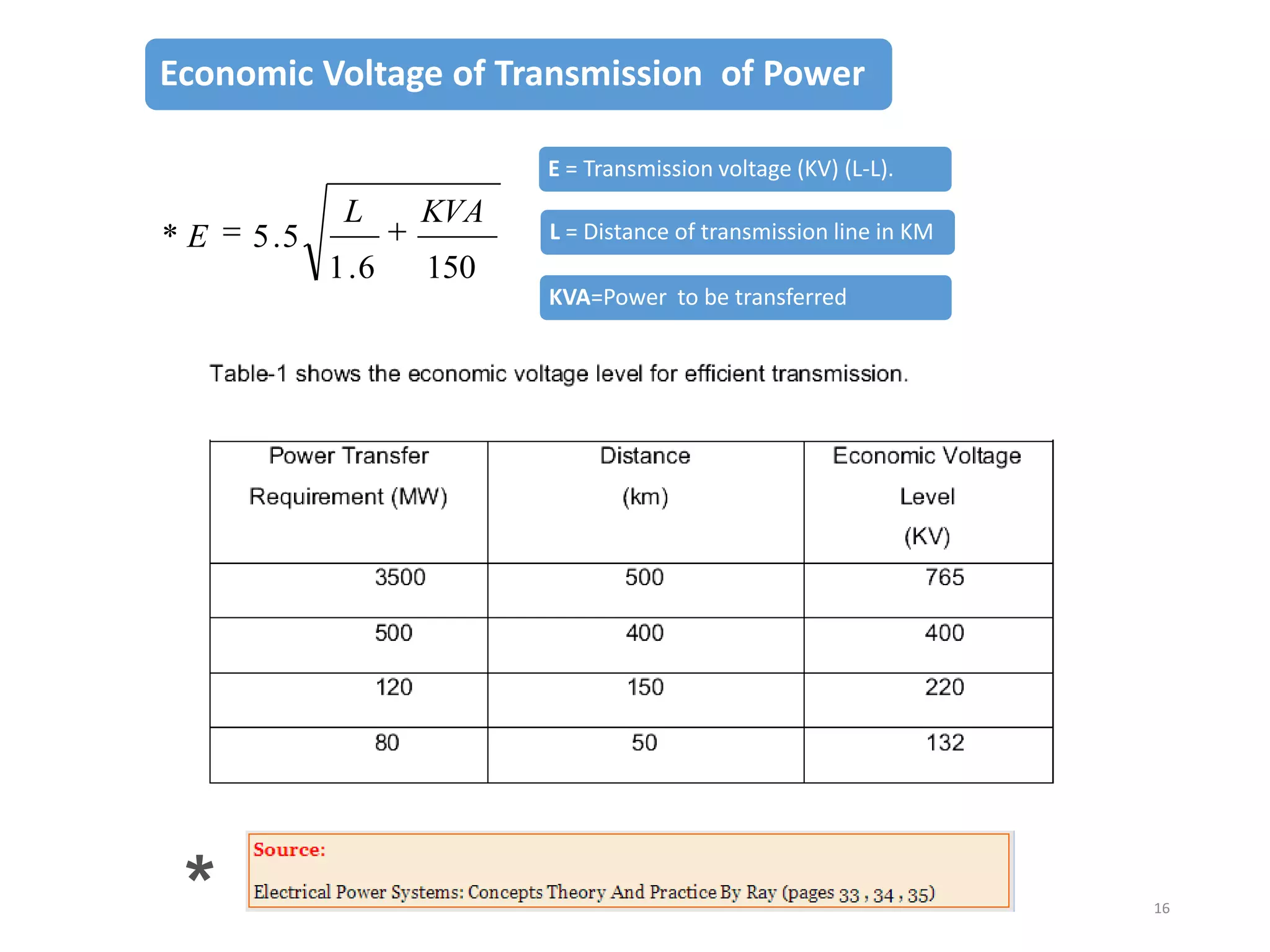
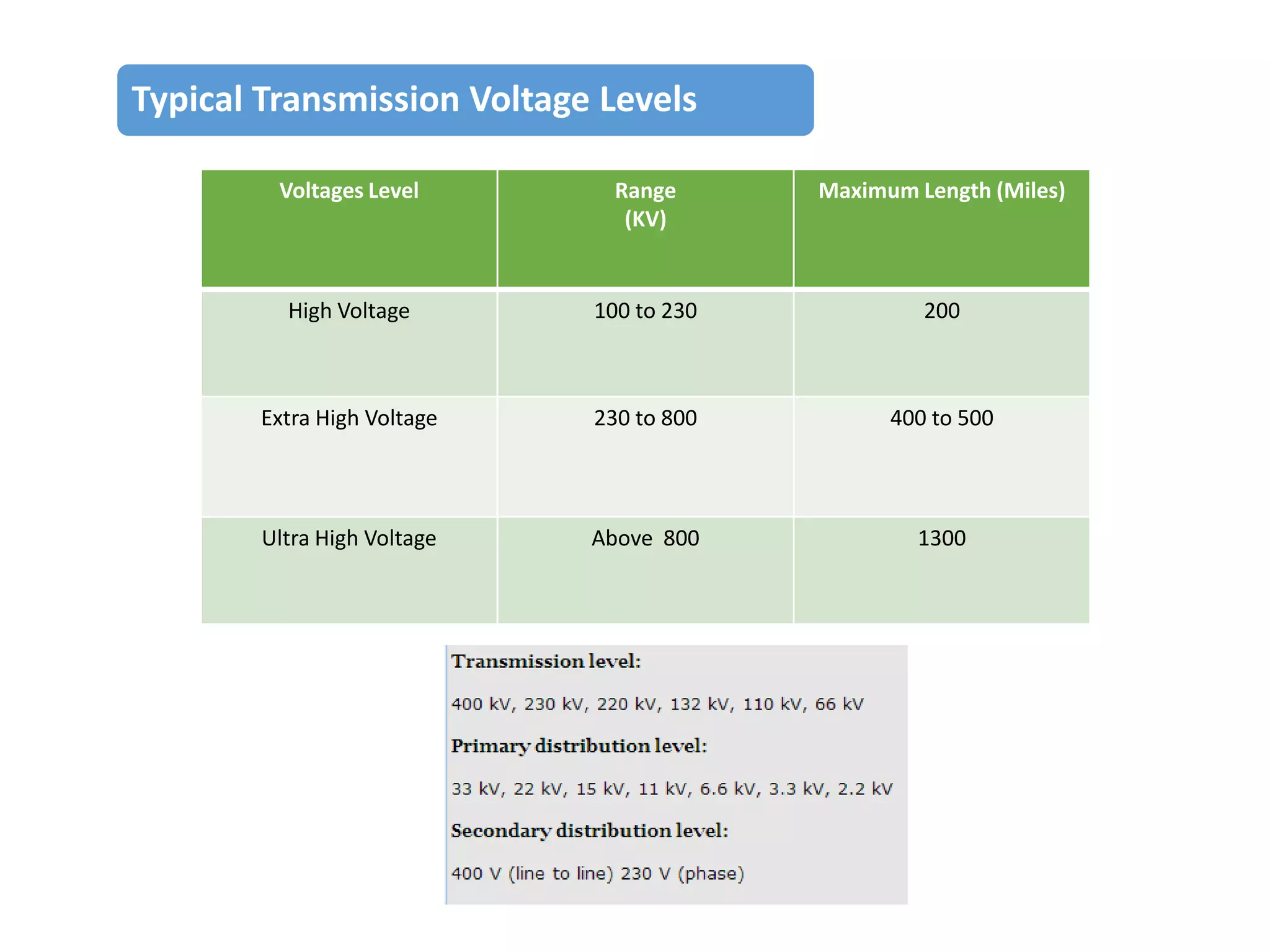
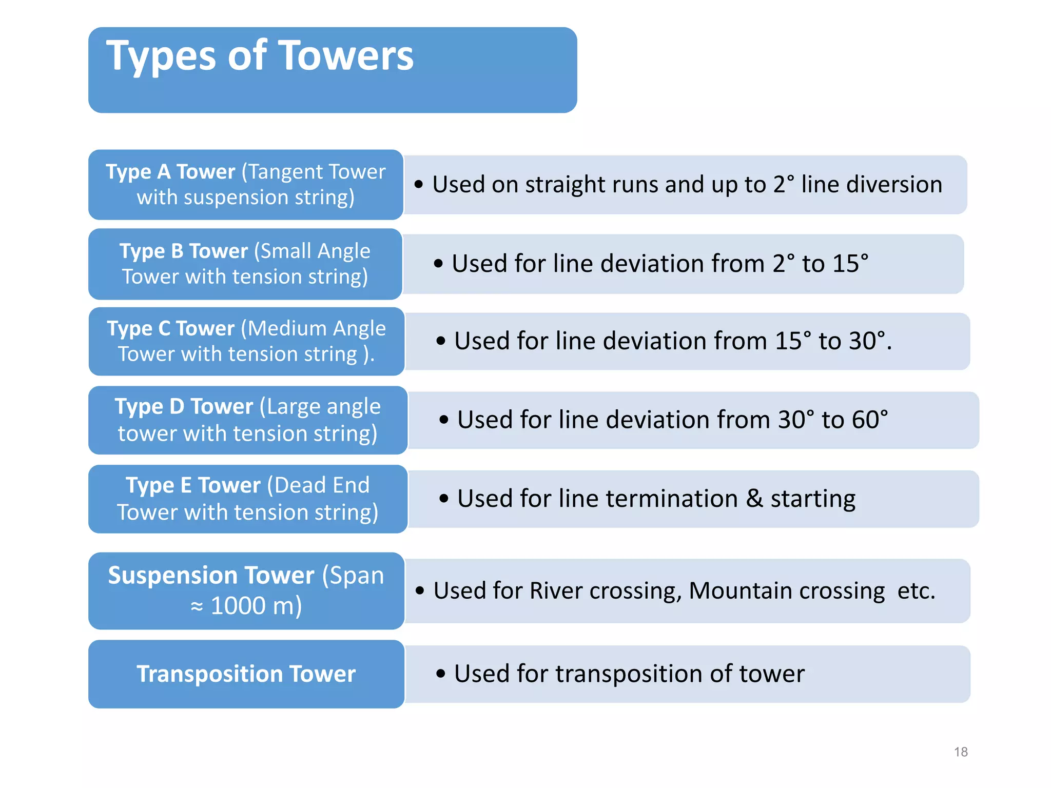
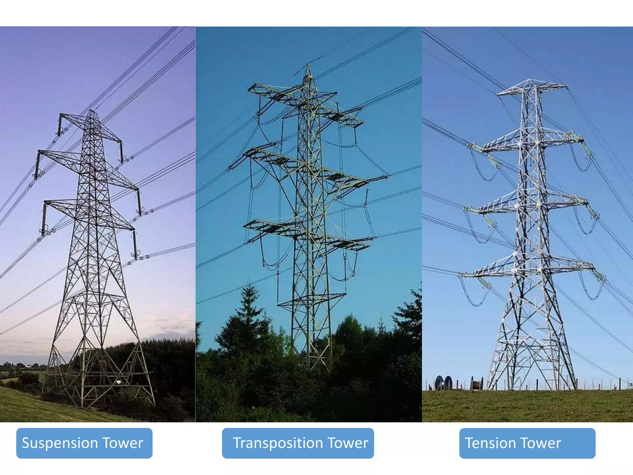
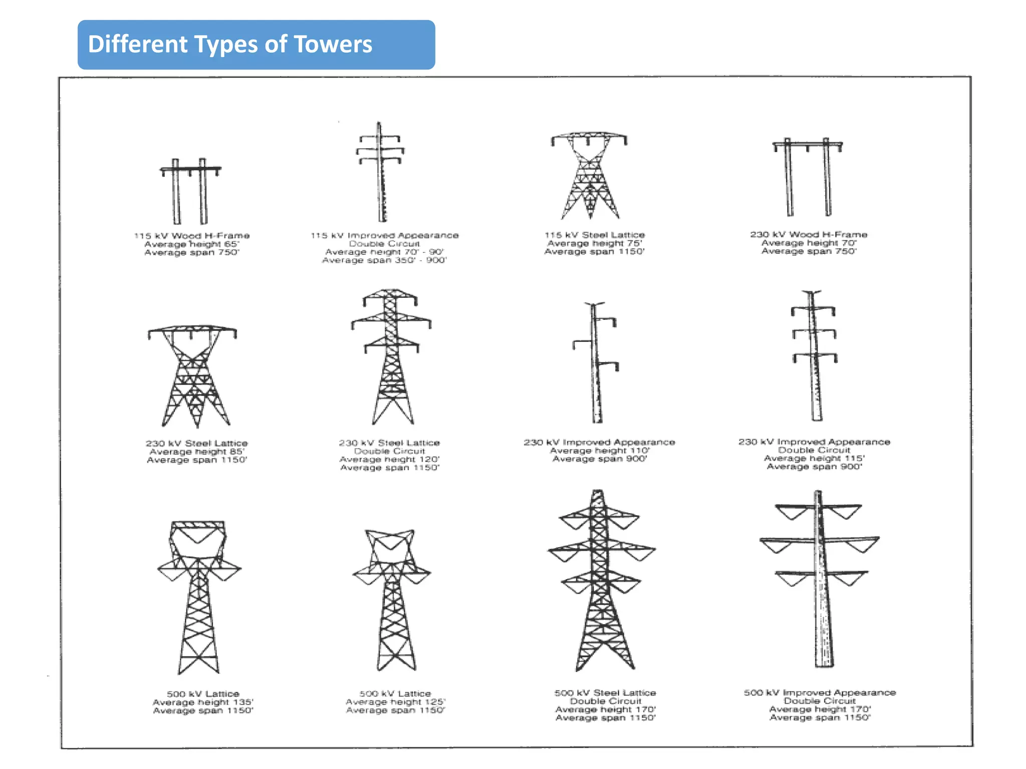
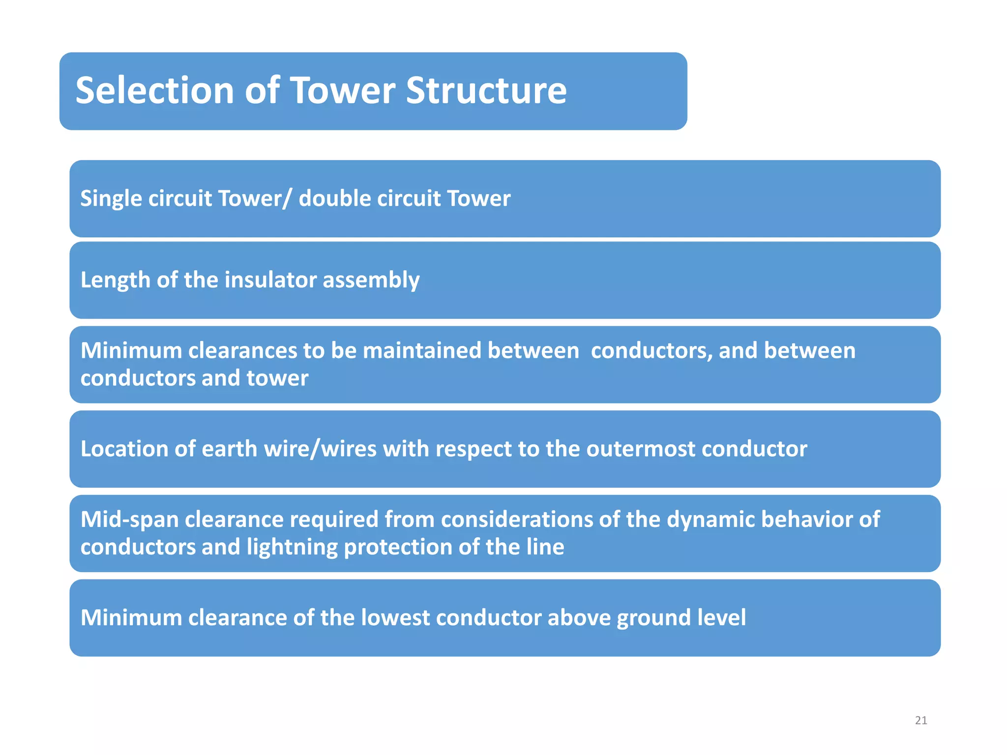


The document outlines the concepts and components involved in energy transmission systems, emphasizing the purpose of efficient electric power distribution from generating stations to consumers. Key components discussed include power generation plants, circuit breakers, insulators, and transmission line design methodology. It also covers various transmission voltages, types of conductors and towers, design criteria for electrical systems, and safety measures such as grounding and insulation.


