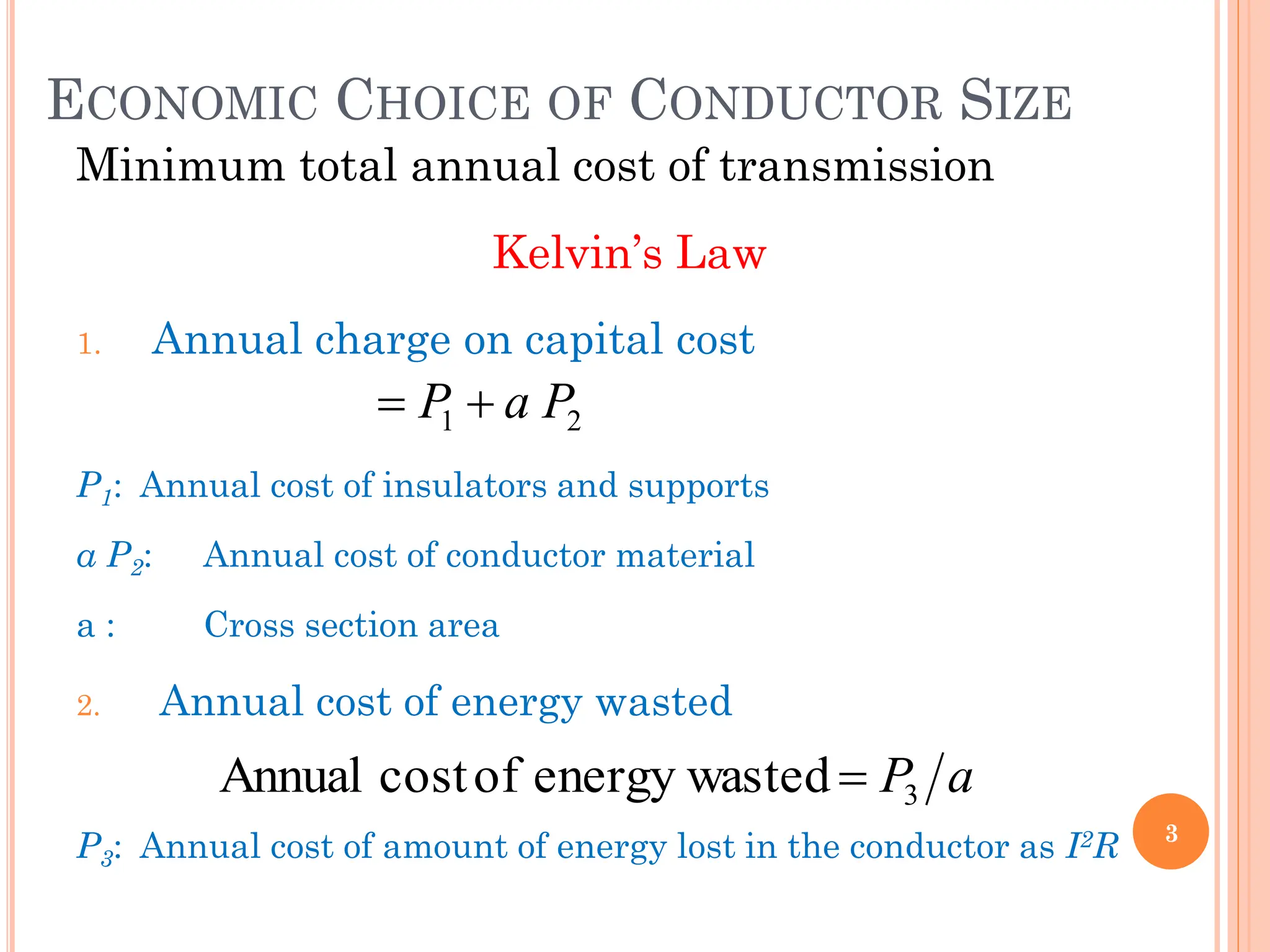
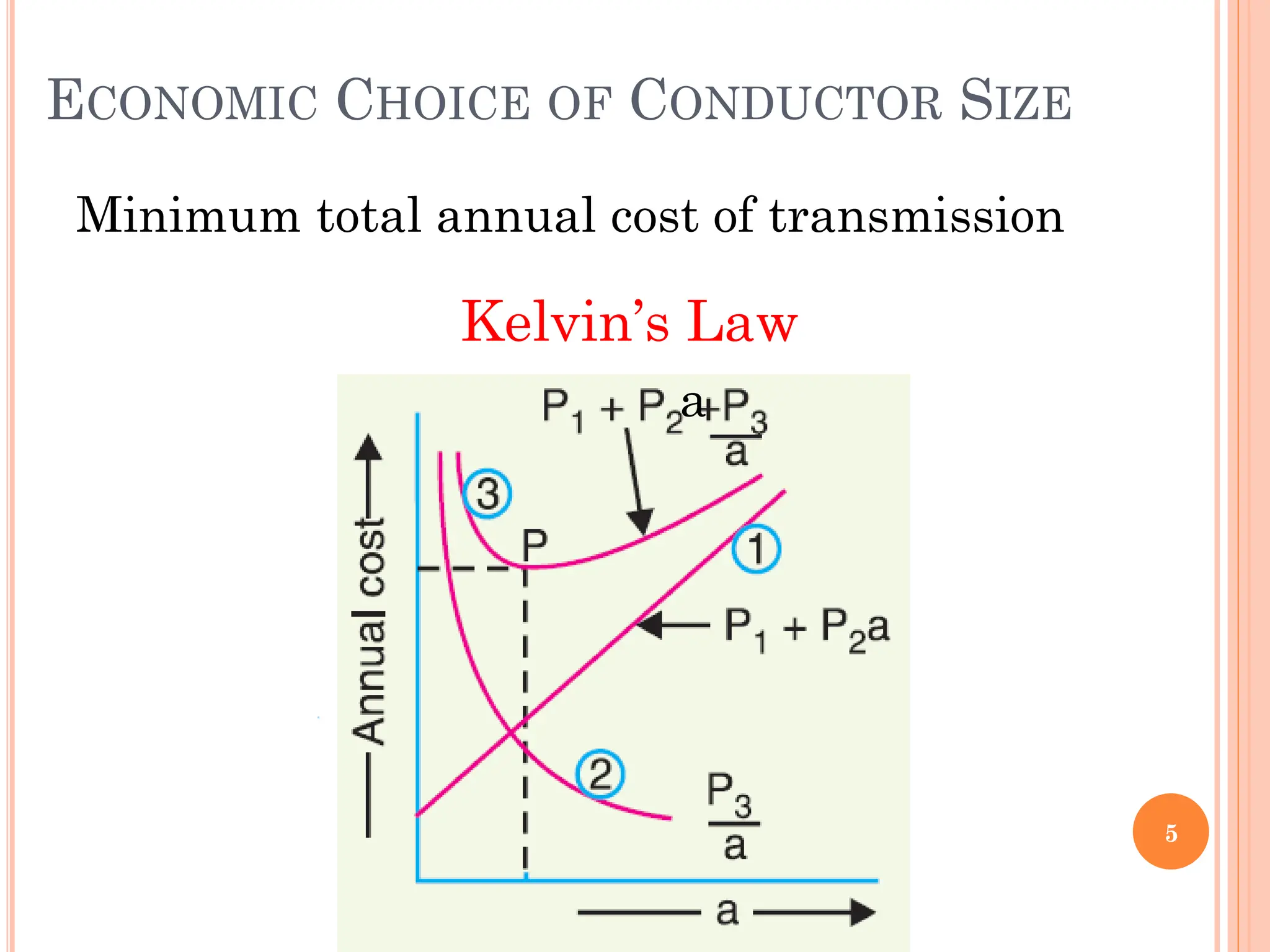
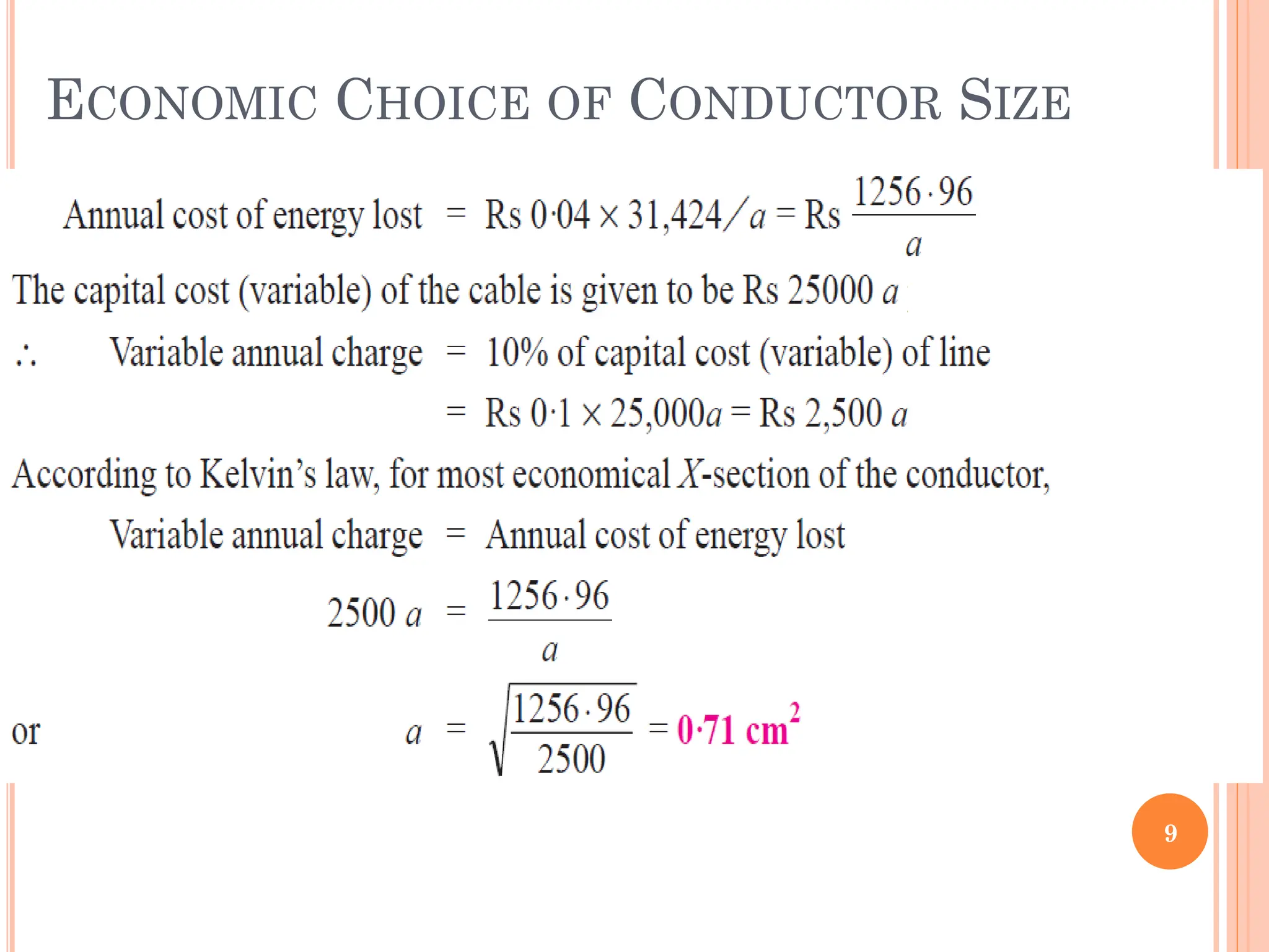
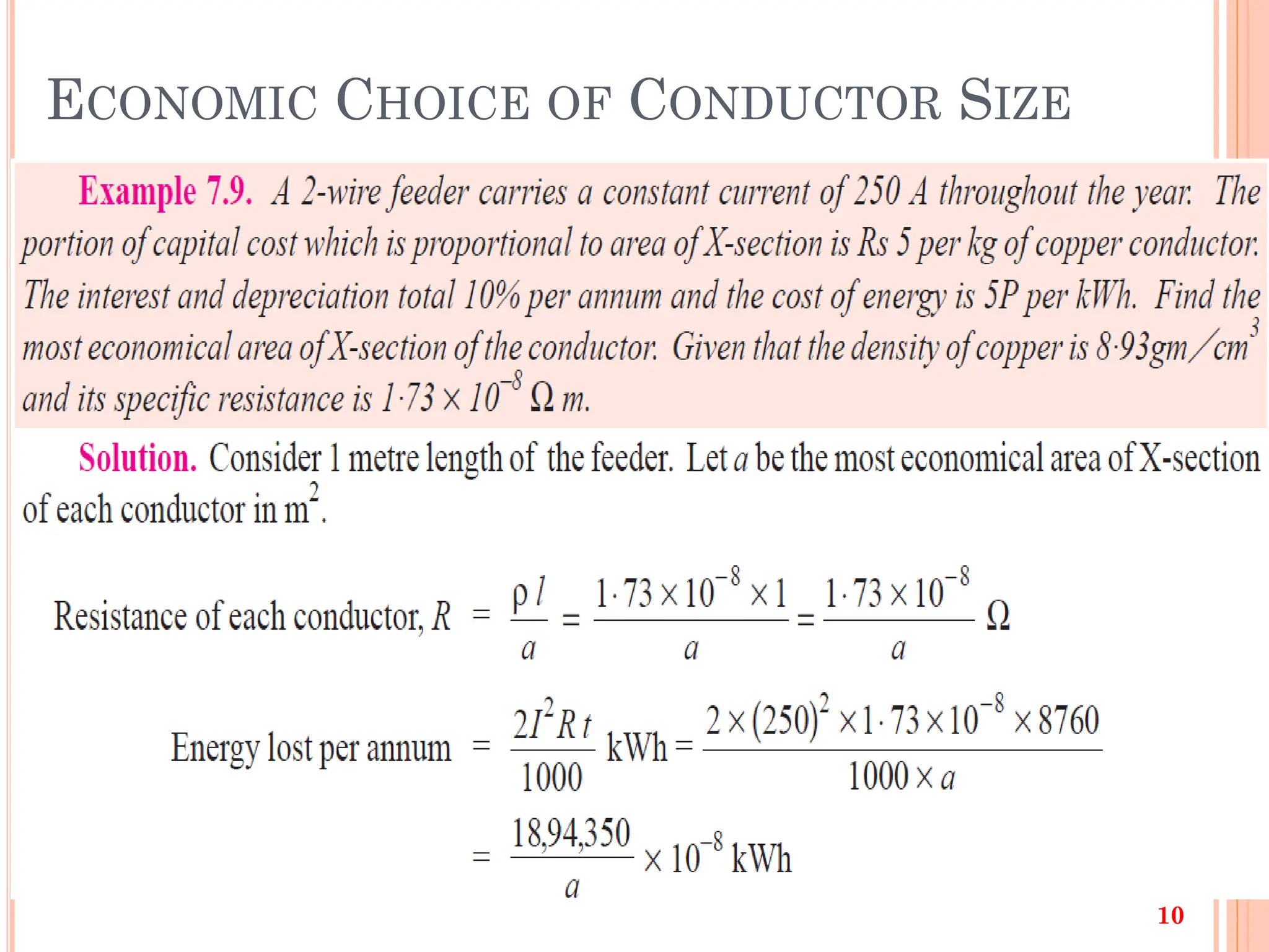
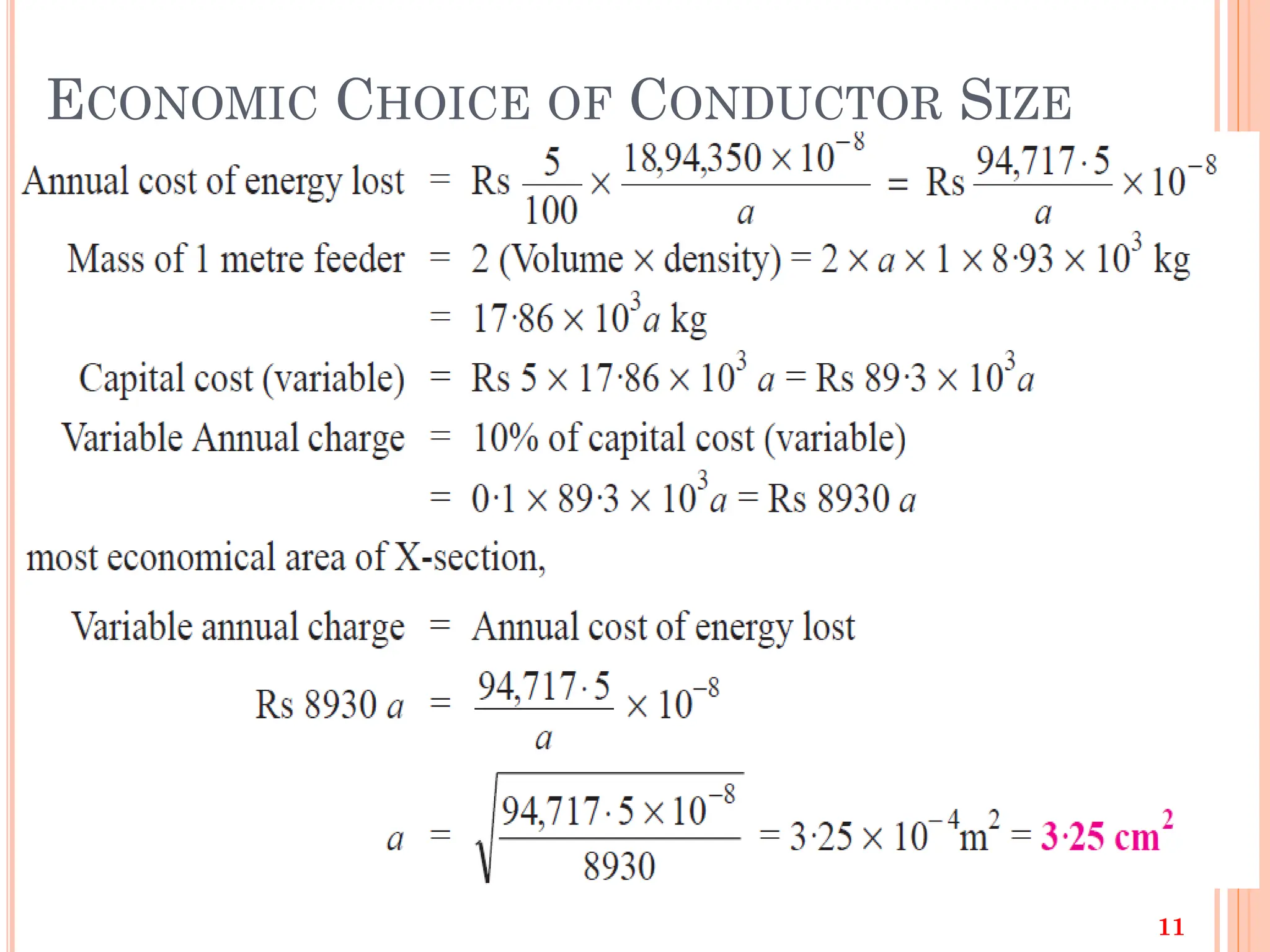
ECONOMIC CHOICE OFCONDUCTOR SIZE
Minimum total annual cost of transmission
Kelvin’s Law
1. Annual charge on capital cost
P1: Annual cost of insulators and supports
a P2: Annual cost of conductor material
a : Cross section area
2. Annual cost of energy wasted
P3: Annual cost of amount of energy lost in the conductor as I2R 3
2
1 P
a
P
a
P3
ted
energy was
of
cost
Annual
4.
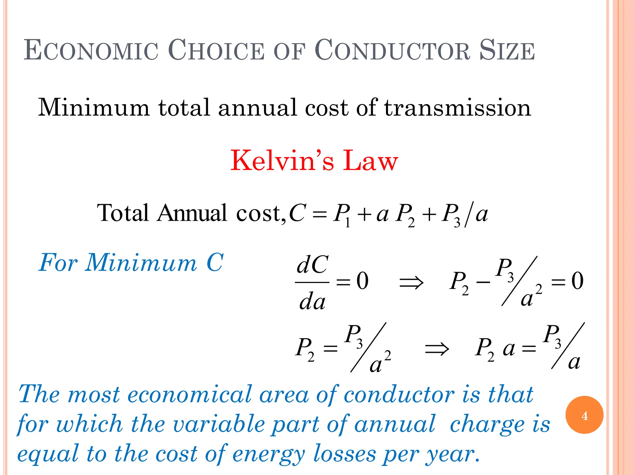
ECONOMIC CHOICE OFCONDUCTOR SIZE
Minimum total annual cost of transmission
Kelvin’s Law
For Minimum C
4
a
P
P
a
P
C 3
2
1
cost,
Annual
Total
a
P
a
P
a
P
P
a
P
P
da
dC
3
2
2
3
2
2
3
2 0
0
The most economical area of conductor is that
for which the variable part of annual charge is
equal to the cost of energy losses per year.
5.
ECONOMIC CHOICE OFCONDUCTOR SIZE
Minimum total annual cost of transmission
Kelvin’s Law
5
a
OBJECTIVES
12
Upon completing thispart, the student should be able to:
Learn typical construction of electrical power systems
List and describe the different types of transmission systems
List and describe the different elements and materials of
transmission systems
Determine the economic choice of conductor size
Determine the economical transmission voltage
Describe the various aspects of mechanical design
13.
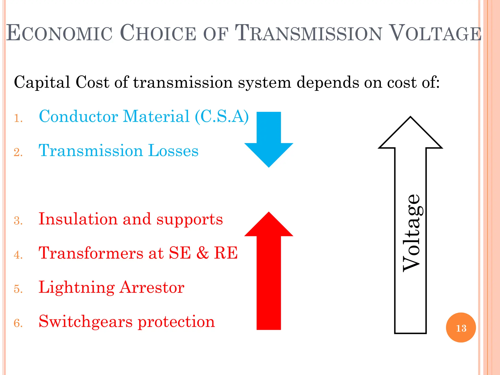
ECONOMIC CHOICE OFTRANSMISSION VOLTAGE
Capital Cost of transmission system depends on cost of:
1. Conductor Material (C.S.A)
2. Transmission Losses
3. Insulation and supports
4. Transformers at SE & RE
5. Lightning Arrestor
6. Switchgears protection 13
Voltage
14.
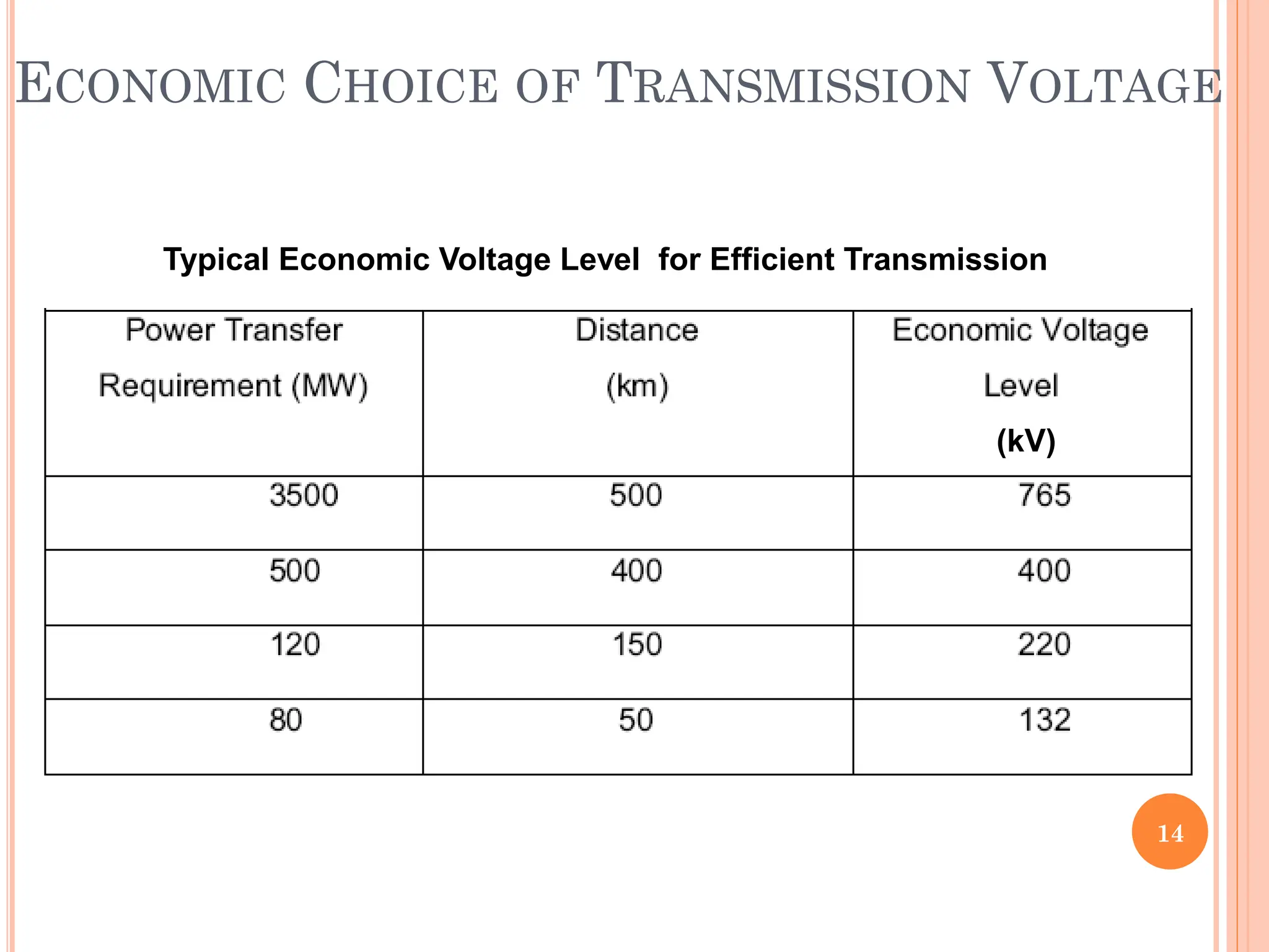
ECONOMIC CHOICE OFTRANSMISSION VOLTAGE
14
(kV)
Typical Economic Voltage Level for Efficient Transmission
15.
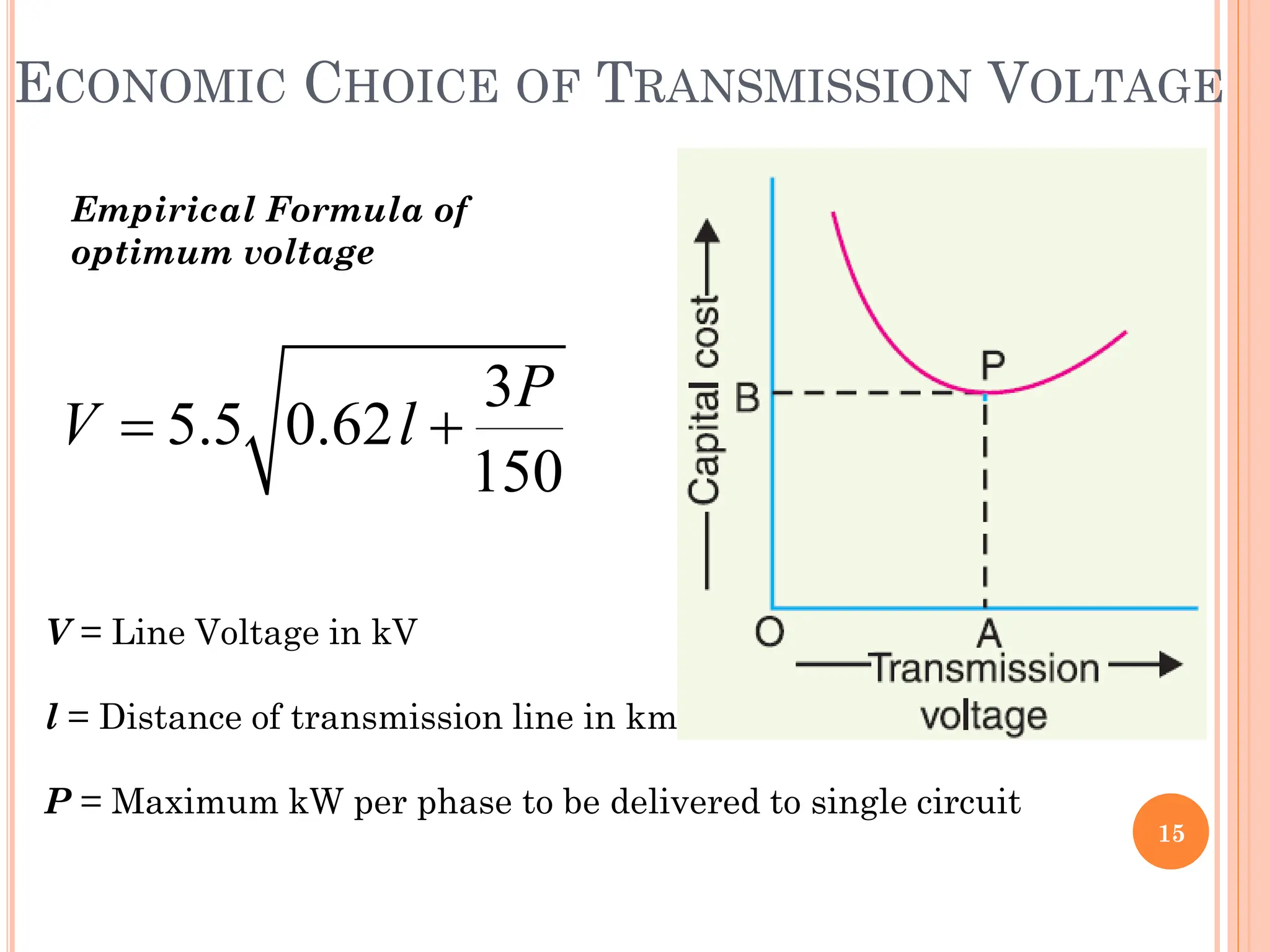
ECONOMIC CHOICE OFTRANSMISSION VOLTAGE
15
3
5.5 0.62
5
1 0
P
V l
V = Line Voltage in kV
l = Distance of transmission line in km
P = Maximum kW per phase to be delivered to single circuit
Empirical Formula of
optimum voltage
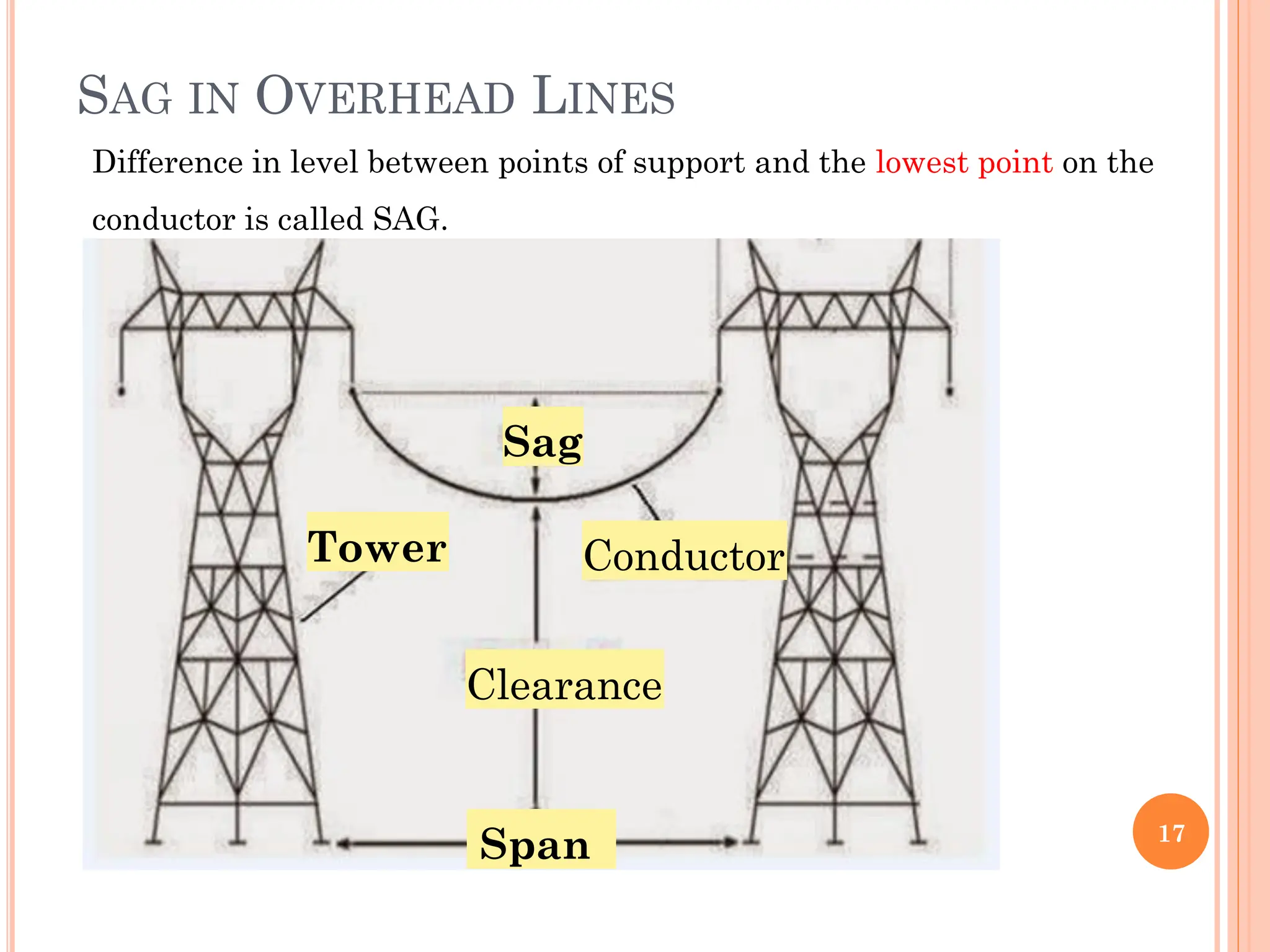
SAG IN OVERHEADLINES
17
Sag
Conductor
Clearance
Tower
Span
Difference in level between points of support and the lowest point on the
conductor is called SAG.
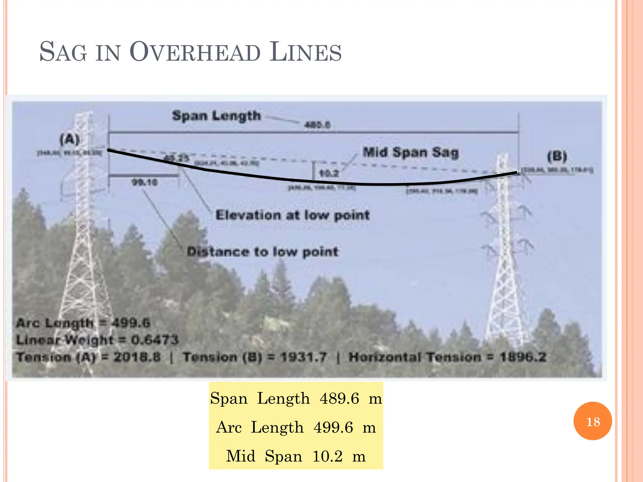
18.
SAG IN OVERHEADLINES
18
Span Length 489.6 m
Arc Length 499.6 m
Mid Span 10.2 m
19.
SAG IN OVERHEADLINES
The conductor sag should kept to a minimum in order
to reduce conductor material required and to avoid
extra tower height.
It is also desirable that tension in the conductor should
be low to avoid mechanical failure of conductor.
However, low conductor tension and minimum sag are
not possible.
19
2
ax
Factor
Safty
Strength
M
Strength
Ultimate
T
Tension
20.
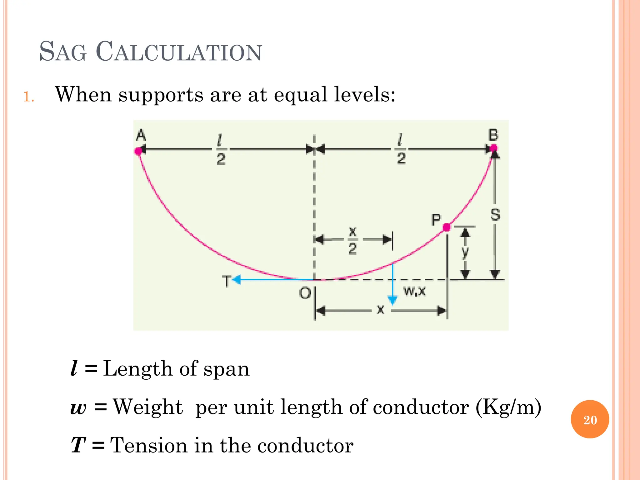
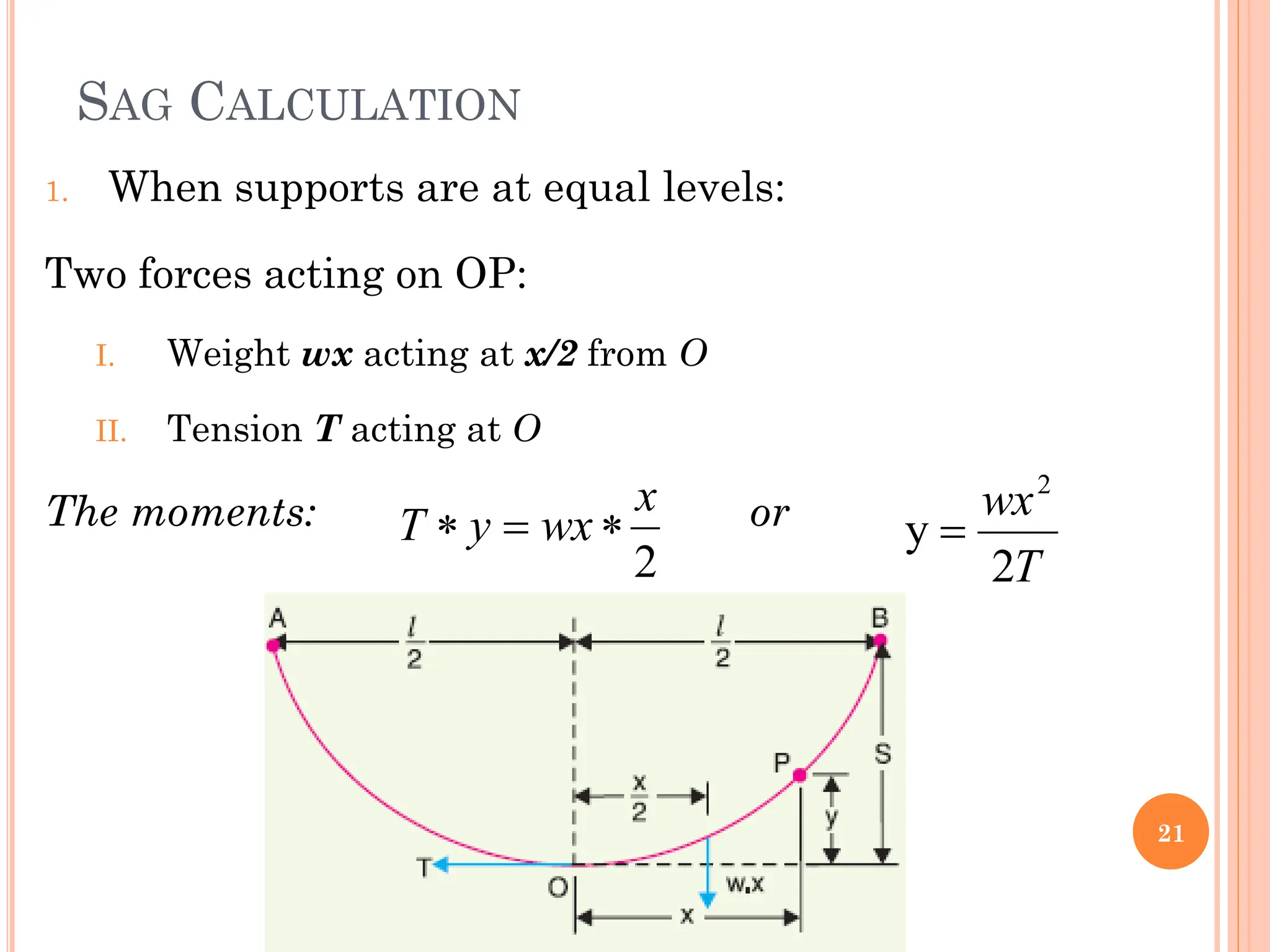
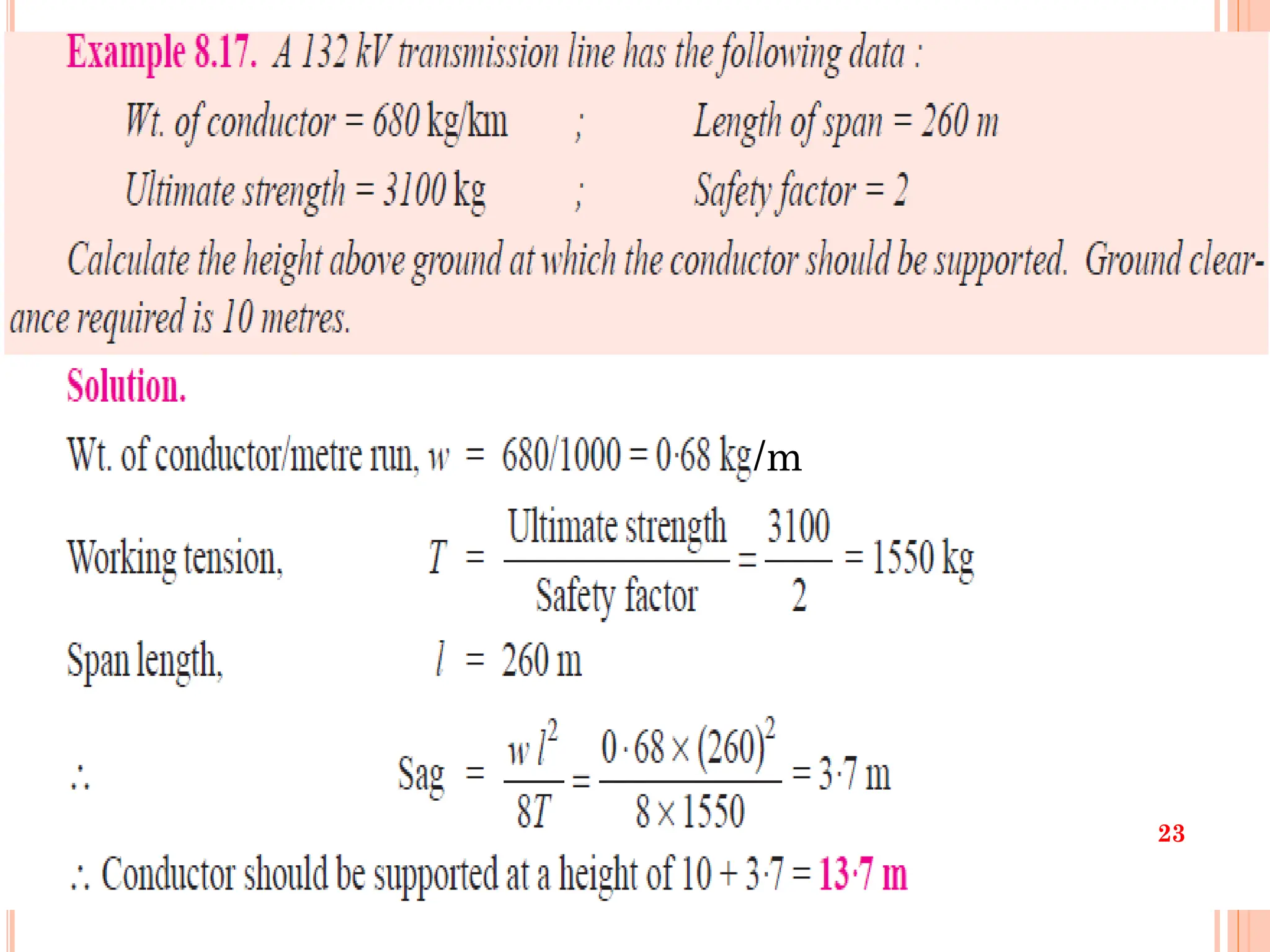
SAG CALCULATION
1. Whensupports are at equal levels:
20
l = Length of span
w = Weight per unit length of conductor (Kg/m)
T = Tension in the conductor
21.
SAG CALCULATION
1. Whensupports are at equal levels:
Two forces acting on OP:
I. Weight wx acting at x/2 from O
II. Tension T acting at O
The moments: or
21
2
x
wx
y
T
T
wx
2
y
2
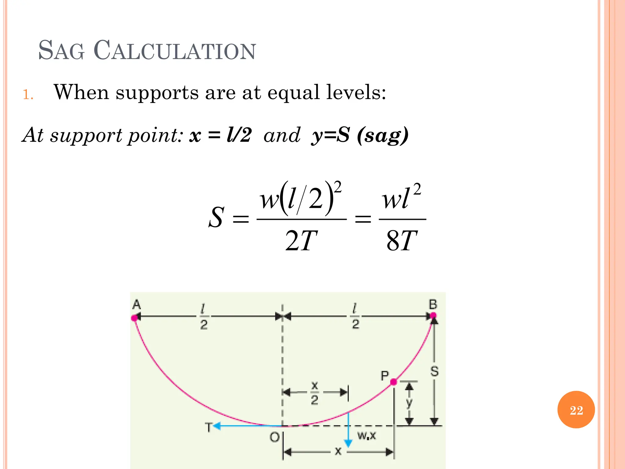
22.
SAG CALCULATION
1. Whensupports are at equal levels:
At support point: x = l/2 and y=S (sag)
22
T
wl
T
l
w
S
8
2
2 2
2
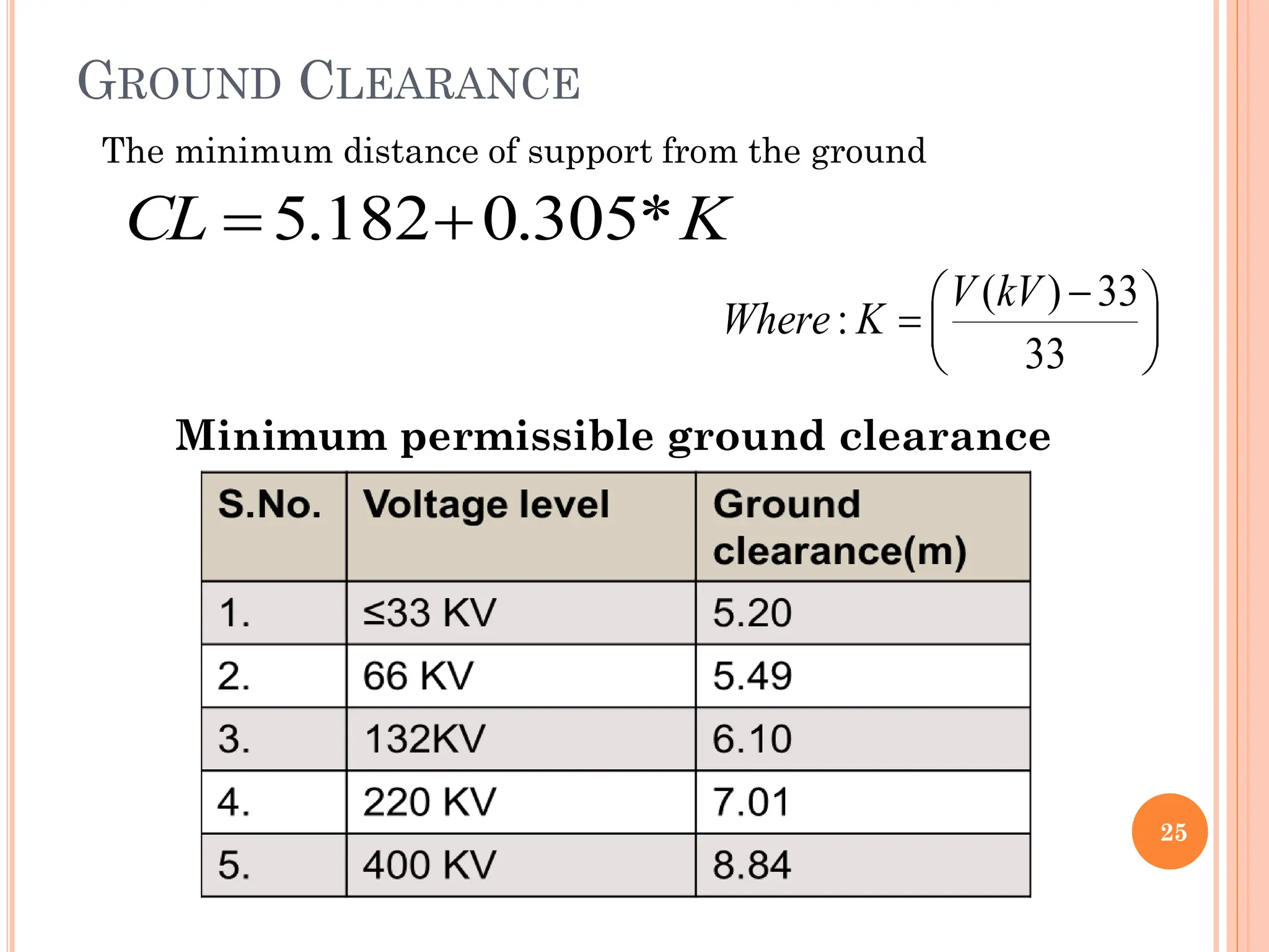
25
( ) 33
:
33
VkV
Where K
GROUND CLEARANCE
K
CL *
305
.
0
182
.
5
Minimum permissible ground clearance
The minimum distance of support from the ground
26.
26
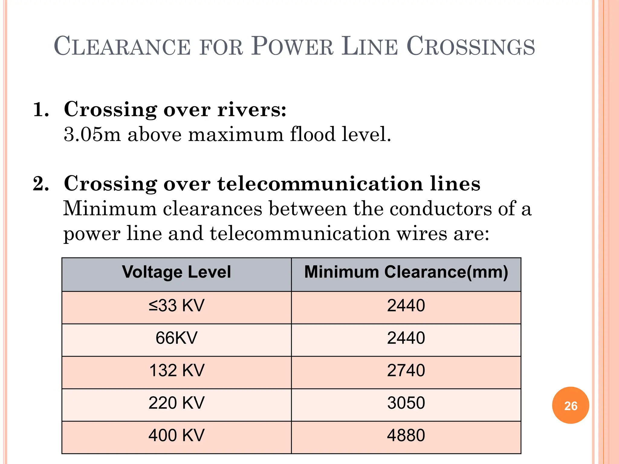
CLEARANCE FOR POWERLINE CROSSINGS
1. Crossing over rivers:
3.05m above maximum flood level.
2. Crossing over telecommunication lines
Minimum clearances between the conductors of a
power line and telecommunication wires are:
Voltage Level Minimum Clearance(mm)
≤33 KV 2440
66KV 2440
132 KV 2740
220 KV 3050
400 KV 4880
27.
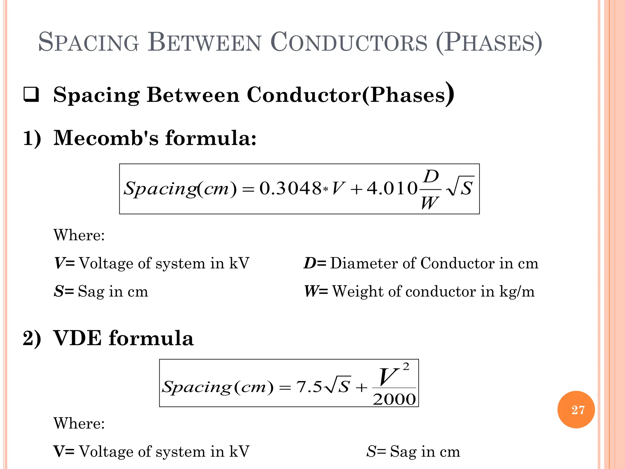
SPACING BETWEEN CONDUCTORS(PHASES)
27
Spacing Between Conductor(Phases)
1) Mecomb's formula:
2) VDE formula
S
W
D
V
cm
Spacing 010
.
4
3048
.
0
)
( *
Where:
V= Voltage of system in kV D= Diameter of Conductor in cm
S= Sag in cm W= Weight of conductor in kg/m
2
( ) 7.5
2000
Spacing cm S V
Where:
V= Voltage of system in kV S= Sag in cm
28.
SPACING BETWEEN CONDUCTORS(PHASES)
28
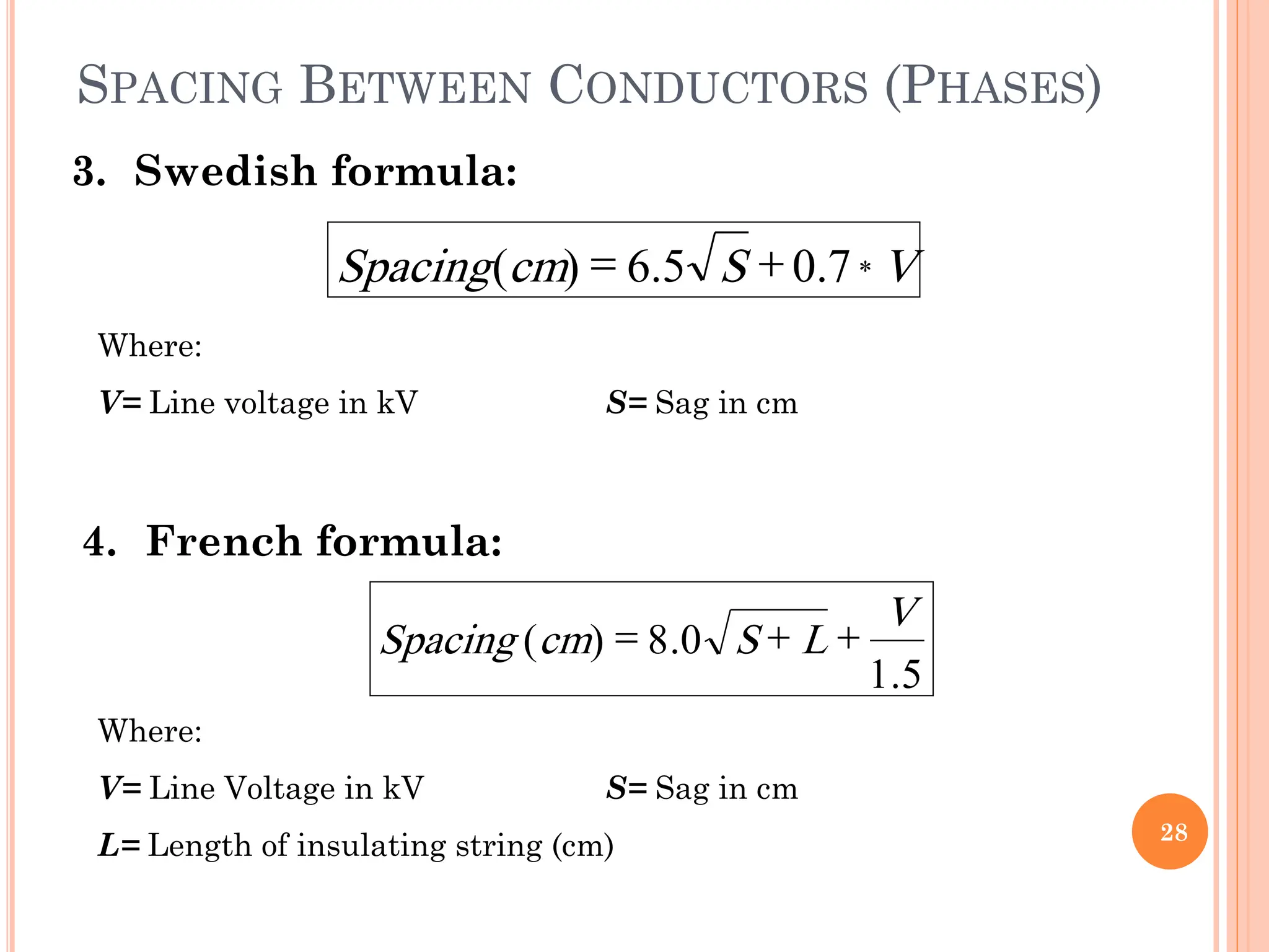
3. Swedish formula:
Where:
V= Line voltage in kV S= Sag in cm
4. French formula:
Where:
V= Line Voltage in kV S= Sag in cm
L= Length of insulating string (cm)
V
S
cm
Spacing *
7
.
0
5
.
6
)
(
5
.
1
0
.
8
)
(
V
L
S
cm
Spacing
29.
SPACING BETWEEN CONDUCTORS(PHASES)
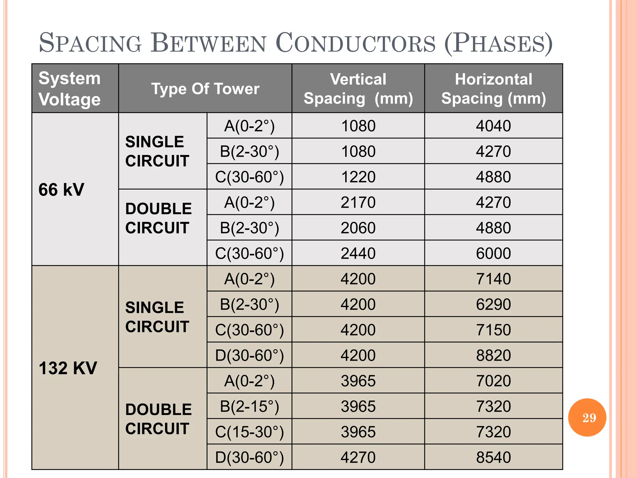
29
System
Voltage
Type Of Tower
Vertical
Spacing (mm)
Horizontal
Spacing (mm)
66 kV
SINGLE
CIRCUIT
A(0-2°) 1080 4040
B(2-30°) 1080 4270
C(30-60°) 1220 4880
DOUBLE
CIRCUIT
A(0-2°) 2170 4270
B(2-30°) 2060 4880
C(30-60°) 2440 6000
132 KV
SINGLE
CIRCUIT
A(0-2°) 4200 7140
B(2-30°) 4200 6290
C(30-60°) 4200 7150
D(30-60°) 4200 8820
DOUBLE
CIRCUIT
A(0-2°) 3965 7020
B(2-15°) 3965 7320
C(15-30°) 3965 7320
D(30-60°) 4270 8540