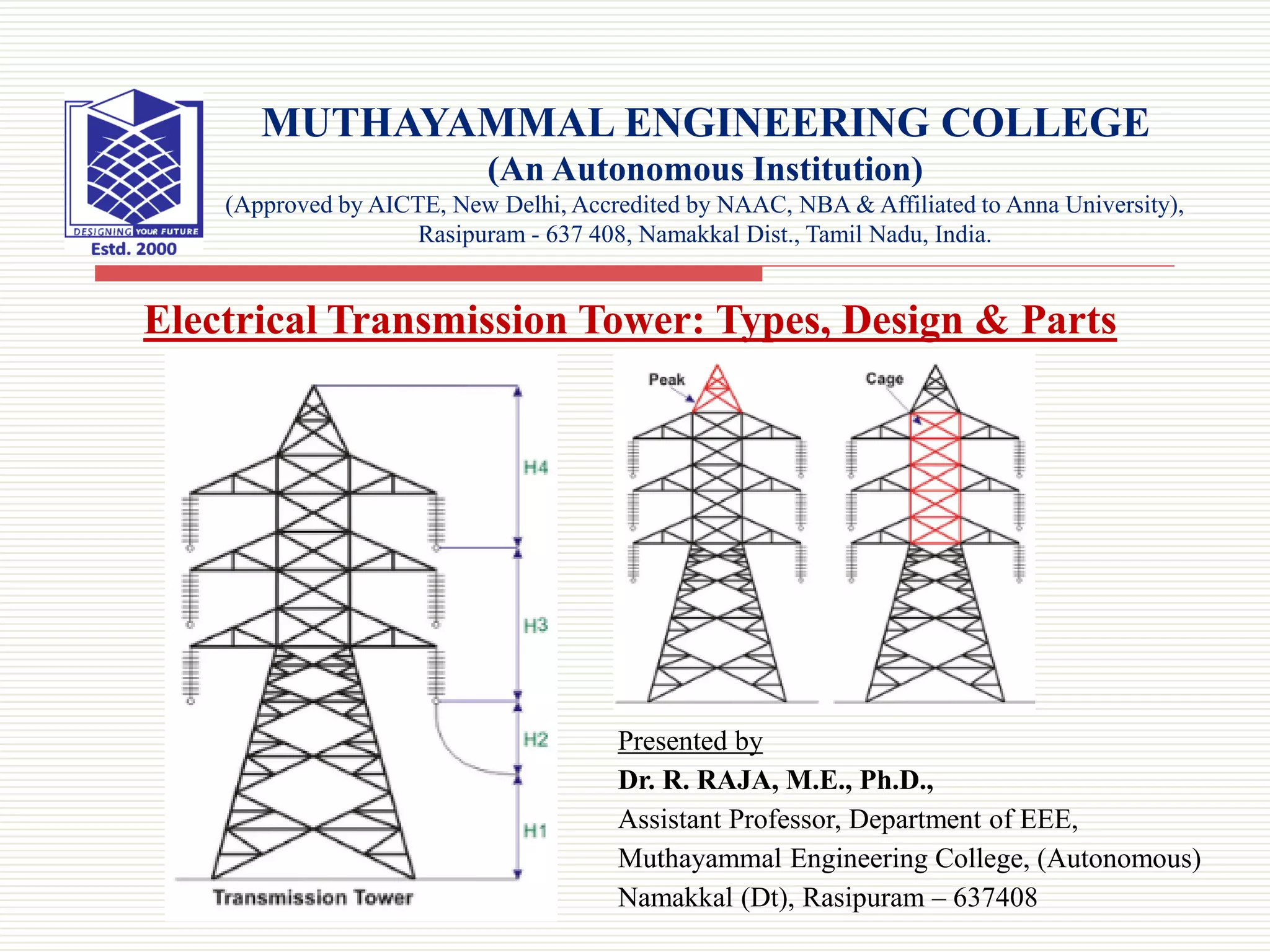
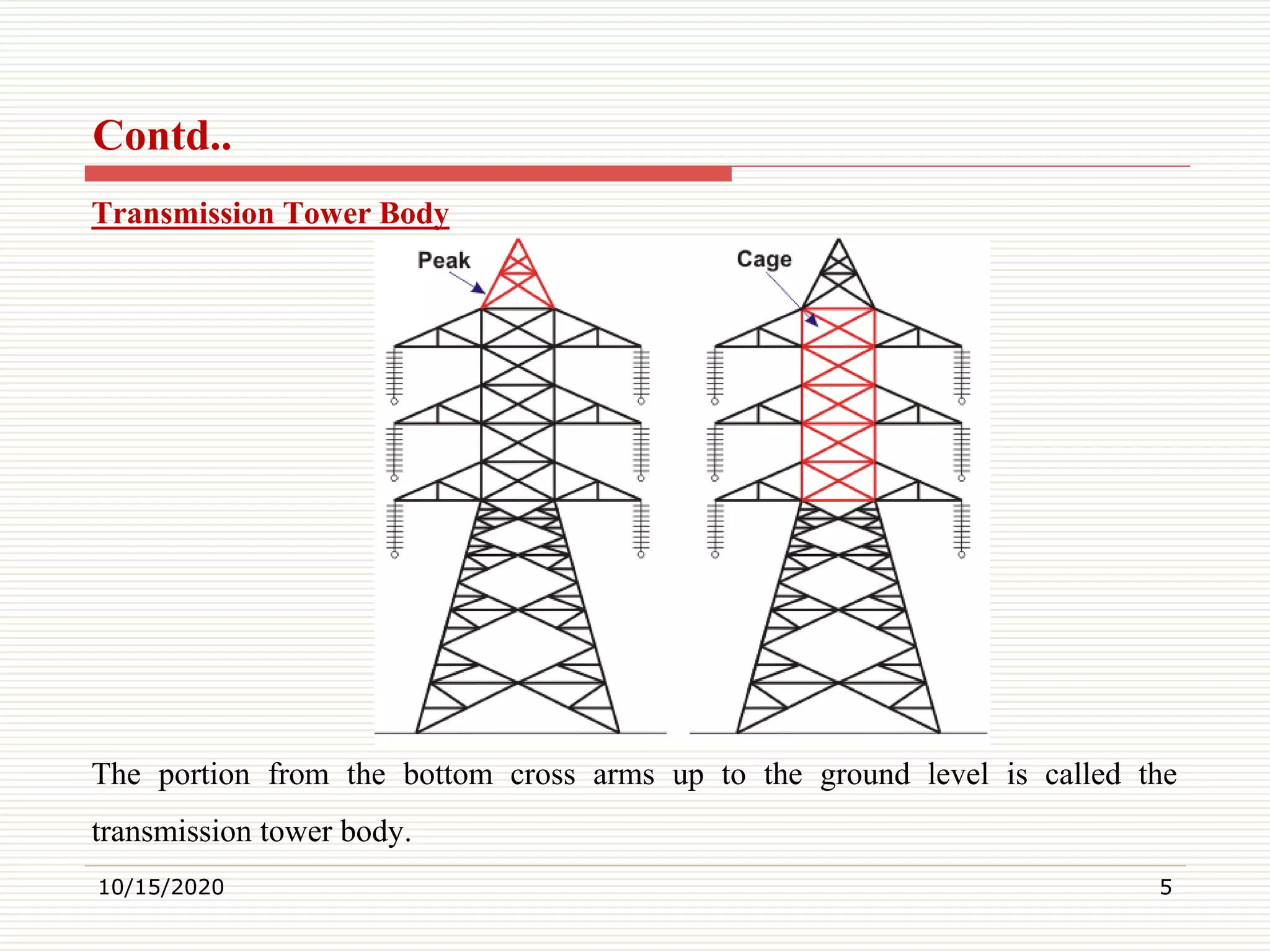
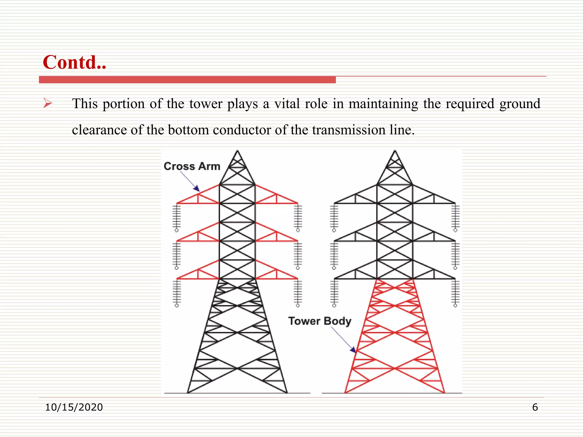
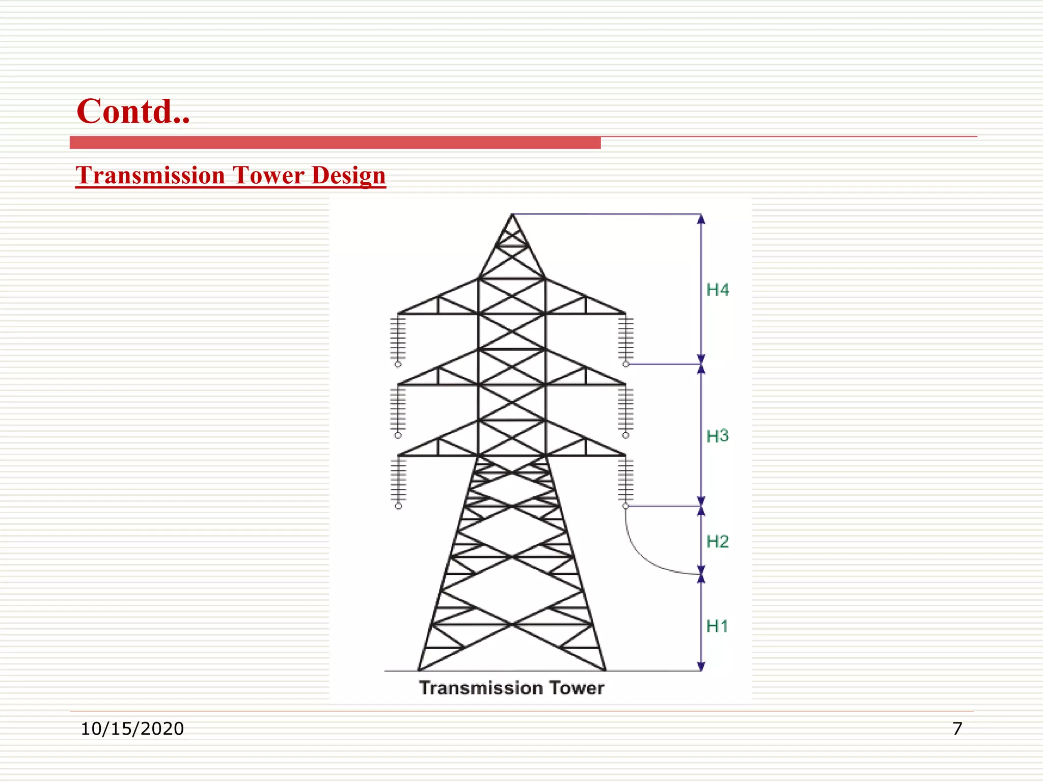
Presented by
Dr. R. RAJA, M.E., Ph.D.,
Assistant Professor, Department of EEE,
Muthayammal Engineering College, (Autonomous)
Namakkal (Dt), Rasipuram – 637408
MUTHAYAMMAL ENGINEERING COLLEGE
(An Autonomous Institution)
(Approved by AICTE, New Delhi, Accredited by NAAC, NBA & Affiliated to Anna University),
Rasipuram - 637 408, Namakkal Dist., Tamil Nadu, India.
Electrical Transmission Tower: Types, Design & Parts
What is a Transmission Tower?
 A transmission tower (also known as a power transmission tower, power tower, or
electricity pylon) is a tall structure (usually a steel lattice tower) used to support an
overhead power line.
 In electrical grids, they are used to carry high voltage transmission lines that transport
bulk electric power from generating stations to electrical substations; utility poles are
used to support lower-voltage sub-transmission and distribution lines that transport
power from substations to electric customers.
 Transmission towers have to carry the heavy transmission conductors at a sufficient
safe height from the ground. In addition to that, all towers have to sustain all kinds of
natural calamities.
 So transmission tower design is an important engineering job where civil, mechanical,
and electrical engineering concepts are equally applicable.
10/15/2020 2
Transmission Tower Parts
 A power transmission tower is a key part of a power transmission system. A
power transmission tower consists of the following parts:
1. The peak of the transmission tower
2. The cross arm of the transmission tower
3. The boom of transmission tower
4. Cage of transmission tower
5. Transmission Tower Body
6. Leg of transmission tower
7. Stub/Anchor Bolt and Baseplate assembly of the transmission tower.
8. These parts have been described below. Note that the construction of these
towers is not a simple task, and there is a tower erection methodology behind
building these high voltage transmission towers.
10/15/2020 3
Peak of Transmission Tower
 The portion above the top cross arm is called peak of transmission tower.
Generally earth shield wire connected to the tip of this peak.
Cross Arm of Transmission Tower
 Cross arms of transmission tower hold the transmission conductor. The
dimension of cross arm depends on the level of transmission voltage,
configuration and minimum forming angle for stress distribution.
Cage of Transmission Tower
 The portion between tower body and peak is known as cage of transmission
tower. This portion of the tower holds the cross arms.
10/15/2020 4
Transmission Tower Body
The portion from the bottom cross arms up to the ground level is called the
transmission tower body.
10/15/2020 5
Contd..
 This portion of the tower plays a vital role in maintaining the required ground
clearance of the bottom conductor of the transmission line.
10/15/2020 6
Contd..
Transmission Tower Design
10/15/2020 7
Contd..
During design of transmission tower the following points to be considered in mind,
 The minimum ground clearance of the lowest conductor point above the ground
level.
 The length of the insulator string.
 The minimum clearance to be maintained between conductors and between
conductor and tower.
 The location of a ground wire with respect to outermost conductors.
 The midspan clearance required from considerations of the dynamic behavior of
the conductor and lightning protection of the power line.
10/15/2020 8
Contd..
 To determine the actual transmission tower height by considering the above
points, we have divided the total height of the tower into four parts:
1. Minimum permissible ground clearance (H1)
2. Maximum sag of the overhead conductor (H2)
3. Vertical spacing between the top and bottom conductors (H3)
4. Vertical clearance between the ground wire and top conductor (H4)
The higher the voltage of the transmission line, the higher the ground clearance and
verticle spacing tends to be. i.e. high voltage towers will have a higher permissible
ground clearance and larger verticle spacing between the top and bottom conductors.
10/15/2020 9
Contd..
Types of Electrical Transmission Towers
 According to different considerations, there are different types of transmission
towers. The transmission line goes as per available corridors.
 Due to the unavailability of the shortest distance straight corridor transmission
line has to deviate from its straightway when obstruction comes.
 In the total length of a long transmission line, there may be several deviation
points. According to the angle of deviation, there are four types of transmission
tower
10/15/2020 10
Contd..
1. A – type tower – angle of deviation 0o to 2o.
2. B – type tower – angle of deviation 2o to 15o.
3. C – type tower – angle of deviation 15o to 30o.
4. D – type tower – angle of deviation 30o to 60o.
 As per the force applied by the conductor on the cross arms, the transmission
towers can be categorized in another way-
 Tangent suspension tower and it is generally A – type tower.
 Angle tower or tension tower or sometime it is called section tower. All B, C
and D types of transmission towers come under this category.
10/15/2020 11
Contd..
 Apart from the above-customized type of tower, the tower is designed to meet
special usages listed below:
These are called special type tower
1. River crossing tower
2. Railway/ Highway crossing tower
3. Transposition tower
Based on numbers of circuits carried by a transmission tower, it can be classisfied as-
1. Single circuit tower
2. Double circuit tower
3. Multi circuit tower.
10/15/2020 12
Contd..
Thank You
10/15/2020 13

Electrical Transmission Tower: Types, Design and Parts

  • 1.
    Presented by Dr. R.RAJA, M.E., Ph.D., Assistant Professor, Department of EEE, Muthayammal Engineering College, (Autonomous) Namakkal (Dt), Rasipuram – 637408 MUTHAYAMMAL ENGINEERING COLLEGE (An Autonomous Institution) (Approved by AICTE, New Delhi, Accredited by NAAC, NBA & Affiliated to Anna University), Rasipuram - 637 408, Namakkal Dist., Tamil Nadu, India. Electrical Transmission Tower: Types, Design & Parts
  • 2.
    What is aTransmission Tower?  A transmission tower (also known as a power transmission tower, power tower, or electricity pylon) is a tall structure (usually a steel lattice tower) used to support an overhead power line.  In electrical grids, they are used to carry high voltage transmission lines that transport bulk electric power from generating stations to electrical substations; utility poles are used to support lower-voltage sub-transmission and distribution lines that transport power from substations to electric customers.  Transmission towers have to carry the heavy transmission conductors at a sufficient safe height from the ground. In addition to that, all towers have to sustain all kinds of natural calamities.  So transmission tower design is an important engineering job where civil, mechanical, and electrical engineering concepts are equally applicable. 10/15/2020 2
  • 3.
    Transmission Tower Parts A power transmission tower is a key part of a power transmission system. A power transmission tower consists of the following parts: 1. The peak of the transmission tower 2. The cross arm of the transmission tower 3. The boom of transmission tower 4. Cage of transmission tower 5. Transmission Tower Body 6. Leg of transmission tower 7. Stub/Anchor Bolt and Baseplate assembly of the transmission tower. 8. These parts have been described below. Note that the construction of these towers is not a simple task, and there is a tower erection methodology behind building these high voltage transmission towers. 10/15/2020 3
  • 4.
    Peak of TransmissionTower  The portion above the top cross arm is called peak of transmission tower. Generally earth shield wire connected to the tip of this peak. Cross Arm of Transmission Tower  Cross arms of transmission tower hold the transmission conductor. The dimension of cross arm depends on the level of transmission voltage, configuration and minimum forming angle for stress distribution. Cage of Transmission Tower  The portion between tower body and peak is known as cage of transmission tower. This portion of the tower holds the cross arms. 10/15/2020 4
  • 5.
    Transmission Tower Body Theportion from the bottom cross arms up to the ground level is called the transmission tower body. 10/15/2020 5 Contd..
  • 6.
     This portionof the tower plays a vital role in maintaining the required ground clearance of the bottom conductor of the transmission line. 10/15/2020 6 Contd..
  • 7.
  • 8.
    During design oftransmission tower the following points to be considered in mind,  The minimum ground clearance of the lowest conductor point above the ground level.  The length of the insulator string.  The minimum clearance to be maintained between conductors and between conductor and tower.  The location of a ground wire with respect to outermost conductors.  The midspan clearance required from considerations of the dynamic behavior of the conductor and lightning protection of the power line. 10/15/2020 8 Contd..
  • 9.
     To determinethe actual transmission tower height by considering the above points, we have divided the total height of the tower into four parts: 1. Minimum permissible ground clearance (H1) 2. Maximum sag of the overhead conductor (H2) 3. Vertical spacing between the top and bottom conductors (H3) 4. Vertical clearance between the ground wire and top conductor (H4) The higher the voltage of the transmission line, the higher the ground clearance and verticle spacing tends to be. i.e. high voltage towers will have a higher permissible ground clearance and larger verticle spacing between the top and bottom conductors. 10/15/2020 9 Contd..
  • 10.
    Types of ElectricalTransmission Towers  According to different considerations, there are different types of transmission towers. The transmission line goes as per available corridors.  Due to the unavailability of the shortest distance straight corridor transmission line has to deviate from its straightway when obstruction comes.  In the total length of a long transmission line, there may be several deviation points. According to the angle of deviation, there are four types of transmission tower 10/15/2020 10 Contd..
  • 11.
    1. A –type tower – angle of deviation 0o to 2o. 2. B – type tower – angle of deviation 2o to 15o. 3. C – type tower – angle of deviation 15o to 30o. 4. D – type tower – angle of deviation 30o to 60o.  As per the force applied by the conductor on the cross arms, the transmission towers can be categorized in another way-  Tangent suspension tower and it is generally A – type tower.  Angle tower or tension tower or sometime it is called section tower. All B, C and D types of transmission towers come under this category. 10/15/2020 11 Contd..
  • 12.
     Apart fromthe above-customized type of tower, the tower is designed to meet special usages listed below: These are called special type tower 1. River crossing tower 2. Railway/ Highway crossing tower 3. Transposition tower Based on numbers of circuits carried by a transmission tower, it can be classisfied as- 1. Single circuit tower 2. Double circuit tower 3. Multi circuit tower. 10/15/2020 12 Contd..
  • 13.