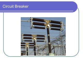
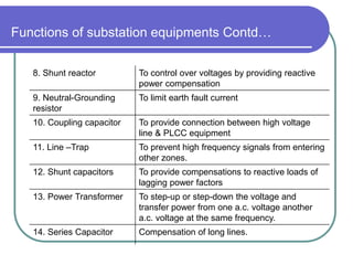
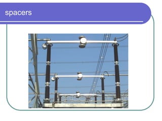
“Sub-station Design”
Agenda
 Overview of sub-station
 Design Process
 Design considerations
 Question / Answer
Imp. considerations in substation design
 Safety of personnel and equipment
 Reliability and Security
 Adherence to
 Statutory obligations
– I.E. rules, Environmental aspects
 Electrical design considerations
 Structural design considerations
 Ease of maintenance
 Possibility to Expand
System parameters
Sr. Description 400kV 220kV
1. Nominal system voltage 400kV 220kV
2. Max. operating voltage 420kV 245kV
3. Rated frequency 50Hz 50Hz
4. Number of phases 3 3
5. System neutral earthing Effectively earthed
6. Corona Extinction voltage 320kV 156kV
7. Min. creepage distance 25mm/kV 25mm/kV
8. Rated short ckt. Current for 1 sec. 40kA 40kA
10. Radio interference voltage at 1MHZ
(for phase to earth voltage)
1000 mV
(320kV)
1000 mV
(156kV)
System parameters Contd..
Sr. Description 400kV 220kV Remarks
11. Rated insulation levels
i) Full wave impulse
withstand voltage
-- for lines
-- for reactor/ X’mer
-- for other equipments
1550kVp
1300kVp
1425kVp
1050kVp
950kVp
1050kVp
ii) Switching impulse
withstand voltage (dry/wet)
1050kVp
iii) One min. power freq.
withstand voltage (dry/wet)
-- for lines
-- for CB / Isolator
-- for other equipments
680kV
520kV
610kV
630kV
460kV
460kV
530kV
460kV
(Line-ground)
(open terminals)
Isolator
P.T
C.T
C.B SF6
Sub station has many component
( C.B., switches , fuses , instrument etc). which must be
housed properly to ensure continues reliable service
Substation Bird’s view
Circuit Breaker
Isolator & Earth Switch
Isolating switches are used to isolate equipment for maintenance. Isolating switches on line side
are provided earthing blade for connection to earth in off position for safety.
Transfer of load from one bus to another by isolators is not recommended. The isolating switches
are designed for no load operation. Inadvertent operation of the isolating switch on load will
damage the switch. Although a variety of disconnect switches are available, the factor which has
the maximum influence on the station layout is whether the
disconnect switch is of the vertical break type or horizontal break type. Horizontal break type
normally occupies more space than the vertical Isolators for 12 kV and 36 kV normal system
voltage conform to IS: 9920 (Part I to IV)
and for voltage 66 kV and above as per IS: 9921.
Earthing switches is a mechanical switching device for earthing parts of a circuit, capable of
withstanding fir a specified time short-circuit currents, but not required to carry normal rated
currents of the circuit.
Disconnecting switches may be motorized or operated manually it is recommended that kV and
above should be motorized. Earthing switches may be manually operated.
In case of double circuit lines the earthing switches shall be capable of switching inductive
(electromagnetically) and capacitive currents (electrostatically induced) as per the values
specified in IEC 62271 – 102 when parallel circuit is energized. The disconnector must
also be capable of interrupting and making parallel circuits when
transferring load between main and reserve bus bars according to IEC requirements.
Current Transformer
CVT
Surge /Lightening Arrester
 Lightening arrestors are the instrument that are used in the incoming feeders so that to prevent
the high voltage entering the main station. This high voltage is very dangerous to the instruments
used in the substation. Even the instruments are very costly, so to prevent any damage lightening
arrestors are used. The lightening arrestors do not let the lightening to fall on the station. If some
lightening occurs the arrestors pull the lightening and ground it to the earth. In any substation the
main important is of protection which is firstly done by these lightening arrestors. The lightening
arrestors are grounded to the earth so that it can pull the lightening to the ground. The lightening
arrestor works with an angle of 30° to 45° making a cone.
 Rating of Lighting Arrestor:
 Size of L.A = 1.5 X Phase to Earth Voltage OR
=1.5 X system Voltage/1.732 OR
= 0.81 X highest System Voltage
 Lighting Arrestor Protection Radius:
 Protection Radius (Rp) = Sqrt (H X (2D-H)+L(2D+L))
H= Actual Height of L.A
D= 20 meter, 40 meter or 60 meter
L= V X T (T=Discharge Time & V= 1m/ms)
Shunt reactors are used in an extra high-voltage
substation to neutralize inductive reactance in long
EHV transmission lines. The photo shows an
installation of both an older version and a newer
version of the reactor.
Shunt Reactor & NGR
Auto Transformer
Transformers
Very large three-phase network transformer.
Bus Post Insulator
 Pin Type Insulators
in type insulators are used for the transmission of lower voltages. A single pin type insulator is used to transmit voltages
up to 11 kV (kilovolts) and higher voltages require two-, three- or four-piece pin insulators. They are not economically
feasible for 33 kV and higher transmission lines. Pin type insulators are secured with steel or lead bolts onto
transmission poles. These are typically used for straight-running transmission lines.
 Suspension Type Insulators
Suspension type transmission line insulators suspend and support high voltage transmission lines. They are cost
effective for higher voltage transmission, typically replacing multiple pin type insulators. Suspension type insulators
have a number of interconnected porcelain discs, with each individual unit designed to support a particular voltage.
Together, a system of these discs is capable of effectively supporting high voltages. There are three types of
suspension insulators: cemented cap suspension insulators; interlinking or Hewlett suspension insulators; and link or
core suspension insulators.
 Strain Type Insulators
Strain type insulators are horizontally suspended suspension insulators. They are used to handle mechanical stresses
and take the pressure off a conductor at the end of a transmission line, at a sharp corner or curve or over long river
crossings. Strain insulators are typically used for higher voltage transmissions.
 Shackle Type Insulators
Shackle type insulators, similar to strain type insulators, are used on sharp curves, end poles and in section poles.
However, unlike strain insulators, shackle insulators are designed to support lower voltages. These insulators are
single, round porcelain parts that are mounted horizontally or vertically.
 Stay Insulators
Stay insulators, also called egg insulators, are primarily used to prevent stay wires from becoming energized from
accidentally broken live wires. They, therefore, function to provide insulation between stay clamps and transmission
poles. Stay insulators are mounted at a height of at least 3 meters (118 inches) from ground level.
Wave Trap
WAVE TRAPPER
 Line trap also is known as Wave trap. What it does is trapping the high frequency
communication signals sent on the line from the remote substation and diverting
them to the telecom/teleportation panel in the substation control room (through
coupling capacitor and LMU).
Capacitive Bank - are used to control the level
of the voltage supplied to the customer by
reducing or eliminating the voltage drop in the
system caused by inductive reactive loads.
Functions of substation equipments
Equipment Function
1. Bus-Bar Incoming & outgoing ckts. Connected to bus-bar
2. Circuit Breaker Automatic switching during normal or abnormal
conditions
3. Isolators Disconnection under no-load condition for
safety, isolation and maintenance.
4. Earthing switch To discharge the voltage on dead lines to earth
5. Current Transformer To step-down currents for measurement, control
& protection
6. Voltage Transformer To step-down voltages for measurement, control
& protection
7. Lightning Arrester To discharge lightning over voltages and
switching over voltages to earth
Functions of substation equipments Contd…
8. Shunt reactor To control over voltages by providing reactive
power compensation
9. Neutral-Grounding
resistor
To limit earth fault current
10. Coupling capacitor To provide connection between high voltage
line & PLCC equipment
11. Line –Trap To prevent high frequency signals from entering
other zones.
12. Shunt capacitors To provide compensations to reactive loads of
lagging power factors
13. Power Transformer To step-up or step-down the voltage and
transfer power from one a.c. voltage another
a.c. voltage at the same frequency.
14. Series Capacitor Compensation of long lines.
Functions of Associated system in substation
System Function
1. Substation Earthing system
-- Earthmat
-- Earthing spikes
-- Earthing risers
To provide an earthmat for connecting
neural points, equipment body, support
structures to earth. For safety of
personnel and for enabling earth fault
protection. To provide the path for
discharging the earth currents from
neutrals, faults, Surge Arresters,
overheads shielding wires etc. with safe
step-potential and touch potential.
2. Overhead earth wire
shielding or Lightning masts.
To protect the outdoor substation
equipment from lightning strokes.
3. Illumination system (lighting)
-- for switchyard
-- buildings
-- roads etc.
43724813-Sub-Station-Engineering.pdf
Contd..
4. Protection system
-- protection relay panels
-- control cables
-- circuit breakers
-- CTs, VTs etc.
To provide alarm or automatic tripping of
faulty part from healthy part and also to
minimize damage to faulty equipment and
associated system.
5. Control cable For Protective circuits, control circuits,
metering circuits, communication circuits
6. Power cable To provide supply path to various
auxiliary equipment and machines.
7. PLCC system power line
carries communication system
-- line trap
-- coupling capacitor
-- PLCC panels
For communication, telemetry, tele-
control, power line carrier protection etc.
Contd…
8. Fire Fighting system
-- Sensors, detection system
-- water spray system
-- fire prot. panels, alarm system
-- watertank and spray system
To sense the occurrence of fire by
sensors and to initiate water spray,
to disconnect power supply to
affected region to pin-point location
of fire by indication in control room.
9. Auxiliary standby power system
-- diesel generator sets
-- switchgear
-- distribution system
For supplying starting power,
standby power for auxiliaries
10. Telephone, telex, microwave,
OPF
For internal and external
communication
TRANSMISSION LINE CONDUCTOR
overhead-Conductor-Library-for-outdoor-
switchyard.xls
Basic drawings for design/construction
 Single Line Diagram
 General Arrangement Drawing
 Electrical Plan and Section
 Control Room Architectural layout
Supporting drawings
 Structural layout
 Earthmat layout
 Civil layout
 Erection Key Diagram
 Lighting Layout
Single Line Diagram – 220kV
General arrangement layout
Electrical layout
Electrical Section
Control room layout
Control room layout
Structural layout
Earthmat Layout
@
@
@
@
@
@
@
@
@
Civil layout
Erection Key Diagram
EW2
EW2
4S1
4S1
4DTTM-2
EW1
4I
4S1
4LA 4P 4V
4S1 4W
4W
4S1
4S1
4I
4S1
4LA
4S1
R1
4SSTM-D
4T1
4T1
4T1
4S1 4S1
4S1
EW2
EW2
4S1
4S1
4S1
4DTTM-1 4S2
4S2 4S2
EW1
4SSTM-D
4TBS
M
4TBS
M 4TBS
M
4P1
4I
4P3
4S1 4S1
4P1
4I
4IC1
4S1 4S1
4S1
4B
4I2 4I1
4I
4IC2
4S1
4C2
4C1 4I1
4B
EW2
EW2
4SSTM-T
4S2 4S2
4TM
4S1 4S1
4S1
4DTTM-1
4DTTM-2
EW1
4S2
4S2 4S2
4I2
4S1
4IC2
4DTTM-1
4DTTM-1
4DTTM-1
4DTTM-1
4DTTM-1
4DTTM-1
4SSTM-D
4LA
4P
4P
4P
4LA
4LA
4W
4V
4V
4V
4W
4SSTM-D
4DTTM-1
4DTTM-1
4DTTM-1
4SSTM-D
4I
4I
4I
4I
4I
4I
4W
4P
4V
4LA
4P
4LA
4V
4P
4LA
4V
4W
4SSTM-D
4DTTM-1
4DTTM-1
4SSTM-D
4I
4I
4I
4I
4DTTM-1
4I
4SSTM-D
4I
4P3
R1
R1
R1
4LA
4LA
4LA
4DTTM-2
4P3
4P3
4I
4I
4I
4DTTM-2
4I
4I
4DTTM-2
4I
R1
R1
R1
4LA
4LA
4LA
4P3
4P3
4I
4I
4DTTM-2
4DTTM-2
4I
4I
4P3
4I
4DTTM-2
4I
4B
4B
4B
4DTQB-2
4DTQB-2 4DTQB-2
4I2
4I1
4I
4P1
4IC2
4P1
4IC1
4I2
4I1
4I1
4B
4B
4B
4C2
4C1
4I1
4I2
4C2
4C1
4I1
4I2
4C2
4C1
4I1
4I2
4B
4B
4B
4P1
4I2
4I1
4IC2
4P1
4IC1
4I2
4I1
4I
4DTQB-1
4DTQB-1 4DTQB-1
4I1
4C2
4C1
4I1
4B
4I2
4B
4C2
4C1
4I1
4I2
4B
4C1
4C2
4I1
4I2
4W1
4W1
4W1
4W1
4W1
4W1
4W1
4W1
4W1
4W1
N1
R2
R2
N1
Lighting Design
 Adequate lighting is necessary for safety of working personnel and O&M
activities
 Recommended value of Illumination level
 Control & Relay panel area - 350 Lux (at floor level)
 Test laboratory - 300 Lux
 Battery room - 100 Lux
 Other indoor area - 150 Lux
 Switchyard - 50 Lux (main equipment)
- 20 Lux (balance Area / road @
ground level)
Single Bus arrangement
Single Bus System
Merits Demerits Remarks
1. Low cost 1. Fault of bus or any
circuit breaker results in
shut-down of entire
substation
1. Used for
distribution
substations upto 33kV
2. Simple to Operate 2. Difficult to do any
maintenance
2. Not used for large
substations.
3. Simple Protection 3. Bus cannot be extended
without completely de-
energizing substations
3. Sectionalizing
increases flexibility
4. Can be used only where
loads can be interrupted or
have other supply
arrangements.
Main & Transfer Bus
Main & transfer busbar system
Merits Demerits Remarks
1. Low initial & ultimate
cost
1. Requires one extra
breaker coupler
1. Used for 110kV
substations where cost
of duplicate bus bar
system is not justified
2. Any breaker can be
taken out of service for
maintenance.
2. Switching is
somewhat complex
when maintaining a
breaker
.
3. Potential devices may
be used on the main bus
3. Fault of bus or any
circuit breaker results in
shutdown of entire
substation.
Double Busbar arrangement
Double Bus Bar Single Breaker system
Merits Demerits Remarks
1. High flexibility 1. Extra bus-coupler circuit
breaker necessary.
1. Most widely
used for 66kV,
132kv, 220kV and
important 11kv,
6.6kV, 3.3kV
substations.
2. Half of the feeders
connected to each bus
2. Bus protection scheme
may cause loss of substation
when it operates.
3. High exposure to bus fault.
4. Line breaker failure takes
all circuits connected to the
bus out of service.
5. Bus couplers failure takes
entire substation out of
service.
Double Busbar with Double breaker
Double Bus Bar Double Breaker system
Merits Demerits Remarks
1. Each has two
associated breakers
1. Most expensive 1. Not used for usual
EHV substations due to
high cost.
2. Has flexibility in
permitting feeder
circuits to be connected
to any bus
2. Would lose half of
the circuits for breaker
fault if circuits are not
connected to both the
buses.
2. Used only for very
important, high power,
EHV substations.
3. Any breaker can be
taken out of service for
maintenance.
4. High reliability
Double main & transfer
Double main bus & transfer bus system
Merits Demerits Remarks
1. Most flexible in operation 1. High cost due to
three buses
1. Preferred by
some utilities
for 400kV and
220kV
important
substations.
2. Highly reliable
3. Breaker failure on bus side
breaker removes only one ckt.
From service
4. All switching done with breakers
5. Simple operation, no isolator
switching required
6. Either main bus can be taken out
of service at any time for
maintenance.
7. Bus fault does not remove any
feeder from the service
One & half breaker scheme
Merits Demerits Remarks
1. Flexible operation for breaker
maintenance
1. One and half
breakers per circuit,
hence higher cost
1. Used for 400kV
& 220kV
substations.
2. Any breaker can be removed
from maintenance without
interruption of load.
2. Protection and
auto-reclosing more
complex since
middle breaker must
be responsive to
both associated
circuits.
2. Preferred.
3. Requires 1 1/2 breaker per
feeder.
4. Each circuit fed by two
breakers.
5. All switching by breaker.
6. Selective tripping
Ring Bus
Mesh (Ring) busbar system
Merits Demerits Remarks
1. Busbars gave
some operational
flexibility
1. If fault occurs during bus
maintenance, ring gets separated
into two sections.
1. Most widely
used for very
large power
stations having
large no. of
incoming and
outgoing lines
and high power
transfer.
2.Auto-reclosing and protection
complex.
3. Requires VT’s on all circuits
because there is no definite voltage
reference point.
These VT’s may be required in all
cases for synchronizing live line or
voltage indication
4. Breaker failure during fault on one
circuit causes loss of additional
circuit because of breaker failure.
Minimum Clearances
400kV 220kV
1. Phase to Earth 3500 mm 2100 mm
2. Phase to phase 4200 mm
(Rod-conductor configuration)
4000 mm
(Conductor-conductor configuration)
2100 mm
3. Sectional clearance 6400 mm 4300 mm
Clearance Diagram
Bus Bar Design
 Continuous current rating. Ampacity caculation as per IEEE:738
 Short time current rating (40kA for 1 Sec.) IEC-865
 Stresses in Tubular Busbar
 Natural frequency of Tubular Busbar
 Deflection of Tube
 Cantilever strength of Post Insulator
 Aeolian Vibrations
Gantry Structure Design
 Sag / Tension calculation : as per IS: 802 1995
Sr. Temp Wind Pressure Limits
1. Min. No wind
2. Min. 36%
3. Every Day No wind T <= 22% of UTS
4. Every Day 100% T <= 70% of UTS
5. Max.
(ACSR 750C/ AAAC 850C)
No wind Clearances
Contd..
 Short Circuit Forces calculation
As per IEC : 865
Short circuit forces during short circuit
Short circuit forces after short circuit
Short circuit forces due to “Pinch” effect for Bundled conductor
Spacer span calculation
 Factor of safety of 2.0 under normal condition and 1.5 under short
circuit condition
spacers
Spacer span Vs Short Ckt. forces
GRAPH OF SPACER SPAN Vs CONDUCTOR TENSION FOR
400 KV TWIN MOOSE ACSR CONDUCTOR
0.00
2000.00
4000.00
6000.00
8000.00
10000.00
12000.00
0 2 4 6 8 10 12 14
SPACER SPAN IN MTRS.
CONDUCTOR
TENSION
PER
PHASE
IN
KG.
Earthing Design
 Guiding standards – IEEE 80, IS:3043, CBIP-223.
 400kV & 220kV system are designed for 40kA.
 Basic Objectives:
 Step potential within tolerable
 Touch Potential limit
 Ground Resistance
 Adequacy of Ground conductor for fault current
(considering corrosion)
Touch and step potential
Lightning Protection – Ground Wire
FIG-4b
FIG-4a
Lightning Protection – Lightning Mast
-2a
-2b
FIG-3.0
TRANSFORMER FIRE AT MINERVA

SUBSTATION DESIGN powerpoint presentation.pptx

  • 1.
  • 2.
    Agenda  Overview ofsub-station  Design Process  Design considerations  Question / Answer
  • 3.
    Imp. considerations insubstation design  Safety of personnel and equipment  Reliability and Security  Adherence to  Statutory obligations – I.E. rules, Environmental aspects  Electrical design considerations  Structural design considerations  Ease of maintenance  Possibility to Expand
  • 4.
    System parameters Sr. Description400kV 220kV 1. Nominal system voltage 400kV 220kV 2. Max. operating voltage 420kV 245kV 3. Rated frequency 50Hz 50Hz 4. Number of phases 3 3 5. System neutral earthing Effectively earthed 6. Corona Extinction voltage 320kV 156kV 7. Min. creepage distance 25mm/kV 25mm/kV 8. Rated short ckt. Current for 1 sec. 40kA 40kA 10. Radio interference voltage at 1MHZ (for phase to earth voltage) 1000 mV (320kV) 1000 mV (156kV)
  • 5.
    System parameters Contd.. Sr.Description 400kV 220kV Remarks 11. Rated insulation levels i) Full wave impulse withstand voltage -- for lines -- for reactor/ X’mer -- for other equipments 1550kVp 1300kVp 1425kVp 1050kVp 950kVp 1050kVp ii) Switching impulse withstand voltage (dry/wet) 1050kVp iii) One min. power freq. withstand voltage (dry/wet) -- for lines -- for CB / Isolator -- for other equipments 680kV 520kV 610kV 630kV 460kV 460kV 530kV 460kV (Line-ground) (open terminals)
  • 6.
    Isolator P.T C.T C.B SF6 Sub stationhas many component ( C.B., switches , fuses , instrument etc). which must be housed properly to ensure continues reliable service
  • 7.
  • 8.
  • 9.
  • 10.
    Isolating switches areused to isolate equipment for maintenance. Isolating switches on line side are provided earthing blade for connection to earth in off position for safety. Transfer of load from one bus to another by isolators is not recommended. The isolating switches are designed for no load operation. Inadvertent operation of the isolating switch on load will damage the switch. Although a variety of disconnect switches are available, the factor which has the maximum influence on the station layout is whether the disconnect switch is of the vertical break type or horizontal break type. Horizontal break type normally occupies more space than the vertical Isolators for 12 kV and 36 kV normal system voltage conform to IS: 9920 (Part I to IV) and for voltage 66 kV and above as per IS: 9921. Earthing switches is a mechanical switching device for earthing parts of a circuit, capable of withstanding fir a specified time short-circuit currents, but not required to carry normal rated currents of the circuit. Disconnecting switches may be motorized or operated manually it is recommended that kV and above should be motorized. Earthing switches may be manually operated. In case of double circuit lines the earthing switches shall be capable of switching inductive (electromagnetically) and capacitive currents (electrostatically induced) as per the values specified in IEC 62271 – 102 when parallel circuit is energized. The disconnector must also be capable of interrupting and making parallel circuits when transferring load between main and reserve bus bars according to IEC requirements.
  • 11.
  • 12.
  • 13.
  • 14.
     Lightening arrestorsare the instrument that are used in the incoming feeders so that to prevent the high voltage entering the main station. This high voltage is very dangerous to the instruments used in the substation. Even the instruments are very costly, so to prevent any damage lightening arrestors are used. The lightening arrestors do not let the lightening to fall on the station. If some lightening occurs the arrestors pull the lightening and ground it to the earth. In any substation the main important is of protection which is firstly done by these lightening arrestors. The lightening arrestors are grounded to the earth so that it can pull the lightening to the ground. The lightening arrestor works with an angle of 30° to 45° making a cone.  Rating of Lighting Arrestor:  Size of L.A = 1.5 X Phase to Earth Voltage OR =1.5 X system Voltage/1.732 OR = 0.81 X highest System Voltage  Lighting Arrestor Protection Radius:  Protection Radius (Rp) = Sqrt (H X (2D-H)+L(2D+L)) H= Actual Height of L.A D= 20 meter, 40 meter or 60 meter L= V X T (T=Discharge Time & V= 1m/ms)
  • 15.
    Shunt reactors areused in an extra high-voltage substation to neutralize inductive reactance in long EHV transmission lines. The photo shows an installation of both an older version and a newer version of the reactor.
  • 16.
  • 17.
  • 18.
  • 19.
  • 22.
     Pin TypeInsulators in type insulators are used for the transmission of lower voltages. A single pin type insulator is used to transmit voltages up to 11 kV (kilovolts) and higher voltages require two-, three- or four-piece pin insulators. They are not economically feasible for 33 kV and higher transmission lines. Pin type insulators are secured with steel or lead bolts onto transmission poles. These are typically used for straight-running transmission lines.  Suspension Type Insulators Suspension type transmission line insulators suspend and support high voltage transmission lines. They are cost effective for higher voltage transmission, typically replacing multiple pin type insulators. Suspension type insulators have a number of interconnected porcelain discs, with each individual unit designed to support a particular voltage. Together, a system of these discs is capable of effectively supporting high voltages. There are three types of suspension insulators: cemented cap suspension insulators; interlinking or Hewlett suspension insulators; and link or core suspension insulators.  Strain Type Insulators Strain type insulators are horizontally suspended suspension insulators. They are used to handle mechanical stresses and take the pressure off a conductor at the end of a transmission line, at a sharp corner or curve or over long river crossings. Strain insulators are typically used for higher voltage transmissions.  Shackle Type Insulators Shackle type insulators, similar to strain type insulators, are used on sharp curves, end poles and in section poles. However, unlike strain insulators, shackle insulators are designed to support lower voltages. These insulators are single, round porcelain parts that are mounted horizontally or vertically.  Stay Insulators Stay insulators, also called egg insulators, are primarily used to prevent stay wires from becoming energized from accidentally broken live wires. They, therefore, function to provide insulation between stay clamps and transmission poles. Stay insulators are mounted at a height of at least 3 meters (118 inches) from ground level.
  • 23.
  • 24.
    WAVE TRAPPER  Linetrap also is known as Wave trap. What it does is trapping the high frequency communication signals sent on the line from the remote substation and diverting them to the telecom/teleportation panel in the substation control room (through coupling capacitor and LMU).
  • 25.
    Capacitive Bank -are used to control the level of the voltage supplied to the customer by reducing or eliminating the voltage drop in the system caused by inductive reactive loads.
  • 27.
    Functions of substationequipments Equipment Function 1. Bus-Bar Incoming & outgoing ckts. Connected to bus-bar 2. Circuit Breaker Automatic switching during normal or abnormal conditions 3. Isolators Disconnection under no-load condition for safety, isolation and maintenance. 4. Earthing switch To discharge the voltage on dead lines to earth 5. Current Transformer To step-down currents for measurement, control & protection 6. Voltage Transformer To step-down voltages for measurement, control & protection 7. Lightning Arrester To discharge lightning over voltages and switching over voltages to earth
  • 28.
    Functions of substationequipments Contd… 8. Shunt reactor To control over voltages by providing reactive power compensation 9. Neutral-Grounding resistor To limit earth fault current 10. Coupling capacitor To provide connection between high voltage line & PLCC equipment 11. Line –Trap To prevent high frequency signals from entering other zones. 12. Shunt capacitors To provide compensations to reactive loads of lagging power factors 13. Power Transformer To step-up or step-down the voltage and transfer power from one a.c. voltage another a.c. voltage at the same frequency. 14. Series Capacitor Compensation of long lines.
  • 29.
    Functions of Associatedsystem in substation System Function 1. Substation Earthing system -- Earthmat -- Earthing spikes -- Earthing risers To provide an earthmat for connecting neural points, equipment body, support structures to earth. For safety of personnel and for enabling earth fault protection. To provide the path for discharging the earth currents from neutrals, faults, Surge Arresters, overheads shielding wires etc. with safe step-potential and touch potential. 2. Overhead earth wire shielding or Lightning masts. To protect the outdoor substation equipment from lightning strokes. 3. Illumination system (lighting) -- for switchyard -- buildings -- roads etc. 43724813-Sub-Station-Engineering.pdf
  • 30.
    Contd.. 4. Protection system --protection relay panels -- control cables -- circuit breakers -- CTs, VTs etc. To provide alarm or automatic tripping of faulty part from healthy part and also to minimize damage to faulty equipment and associated system. 5. Control cable For Protective circuits, control circuits, metering circuits, communication circuits 6. Power cable To provide supply path to various auxiliary equipment and machines. 7. PLCC system power line carries communication system -- line trap -- coupling capacitor -- PLCC panels For communication, telemetry, tele- control, power line carrier protection etc.
  • 31.
    Contd… 8. Fire Fightingsystem -- Sensors, detection system -- water spray system -- fire prot. panels, alarm system -- watertank and spray system To sense the occurrence of fire by sensors and to initiate water spray, to disconnect power supply to affected region to pin-point location of fire by indication in control room. 9. Auxiliary standby power system -- diesel generator sets -- switchgear -- distribution system For supplying starting power, standby power for auxiliaries 10. Telephone, telex, microwave, OPF For internal and external communication
  • 32.
  • 33.
    Basic drawings fordesign/construction  Single Line Diagram  General Arrangement Drawing  Electrical Plan and Section  Control Room Architectural layout
  • 34.
    Supporting drawings  Structurallayout  Earthmat layout  Civil layout  Erection Key Diagram  Lighting Layout
  • 35.
  • 36.
  • 37.
  • 38.
  • 39.
  • 40.
  • 41.
  • 42.
  • 43.
  • 44.
    Erection Key Diagram EW2 EW2 4S1 4S1 4DTTM-2 EW1 4I 4S1 4LA4P 4V 4S1 4W 4W 4S1 4S1 4I 4S1 4LA 4S1 R1 4SSTM-D 4T1 4T1 4T1 4S1 4S1 4S1 EW2 EW2 4S1 4S1 4S1 4DTTM-1 4S2 4S2 4S2 EW1 4SSTM-D 4TBS M 4TBS M 4TBS M 4P1 4I 4P3 4S1 4S1 4P1 4I 4IC1 4S1 4S1 4S1 4B 4I2 4I1 4I 4IC2 4S1 4C2 4C1 4I1 4B EW2 EW2 4SSTM-T 4S2 4S2 4TM 4S1 4S1 4S1 4DTTM-1 4DTTM-2 EW1 4S2 4S2 4S2 4I2 4S1 4IC2 4DTTM-1 4DTTM-1 4DTTM-1 4DTTM-1 4DTTM-1 4DTTM-1 4SSTM-D 4LA 4P 4P 4P 4LA 4LA 4W 4V 4V 4V 4W 4SSTM-D 4DTTM-1 4DTTM-1 4DTTM-1 4SSTM-D 4I 4I 4I 4I 4I 4I 4W 4P 4V 4LA 4P 4LA 4V 4P 4LA 4V 4W 4SSTM-D 4DTTM-1 4DTTM-1 4SSTM-D 4I 4I 4I 4I 4DTTM-1 4I 4SSTM-D 4I 4P3 R1 R1 R1 4LA 4LA 4LA 4DTTM-2 4P3 4P3 4I 4I 4I 4DTTM-2 4I 4I 4DTTM-2 4I R1 R1 R1 4LA 4LA 4LA 4P3 4P3 4I 4I 4DTTM-2 4DTTM-2 4I 4I 4P3 4I 4DTTM-2 4I 4B 4B 4B 4DTQB-2 4DTQB-2 4DTQB-2 4I2 4I1 4I 4P1 4IC2 4P1 4IC1 4I2 4I1 4I1 4B 4B 4B 4C2 4C1 4I1 4I2 4C2 4C1 4I1 4I2 4C2 4C1 4I1 4I2 4B 4B 4B 4P1 4I2 4I1 4IC2 4P1 4IC1 4I2 4I1 4I 4DTQB-1 4DTQB-1 4DTQB-1 4I1 4C2 4C1 4I1 4B 4I2 4B 4C2 4C1 4I1 4I2 4B 4C1 4C2 4I1 4I2 4W1 4W1 4W1 4W1 4W1 4W1 4W1 4W1 4W1 4W1 N1 R2 R2 N1
  • 45.
    Lighting Design  Adequatelighting is necessary for safety of working personnel and O&M activities  Recommended value of Illumination level  Control & Relay panel area - 350 Lux (at floor level)  Test laboratory - 300 Lux  Battery room - 100 Lux  Other indoor area - 150 Lux  Switchyard - 50 Lux (main equipment) - 20 Lux (balance Area / road @ ground level)
  • 46.
  • 47.
    Single Bus System MeritsDemerits Remarks 1. Low cost 1. Fault of bus or any circuit breaker results in shut-down of entire substation 1. Used for distribution substations upto 33kV 2. Simple to Operate 2. Difficult to do any maintenance 2. Not used for large substations. 3. Simple Protection 3. Bus cannot be extended without completely de- energizing substations 3. Sectionalizing increases flexibility 4. Can be used only where loads can be interrupted or have other supply arrangements.
  • 48.
  • 49.
    Main & transferbusbar system Merits Demerits Remarks 1. Low initial & ultimate cost 1. Requires one extra breaker coupler 1. Used for 110kV substations where cost of duplicate bus bar system is not justified 2. Any breaker can be taken out of service for maintenance. 2. Switching is somewhat complex when maintaining a breaker . 3. Potential devices may be used on the main bus 3. Fault of bus or any circuit breaker results in shutdown of entire substation.
  • 50.
  • 51.
    Double Bus BarSingle Breaker system Merits Demerits Remarks 1. High flexibility 1. Extra bus-coupler circuit breaker necessary. 1. Most widely used for 66kV, 132kv, 220kV and important 11kv, 6.6kV, 3.3kV substations. 2. Half of the feeders connected to each bus 2. Bus protection scheme may cause loss of substation when it operates. 3. High exposure to bus fault. 4. Line breaker failure takes all circuits connected to the bus out of service. 5. Bus couplers failure takes entire substation out of service.
  • 52.
    Double Busbar withDouble breaker
  • 53.
    Double Bus BarDouble Breaker system Merits Demerits Remarks 1. Each has two associated breakers 1. Most expensive 1. Not used for usual EHV substations due to high cost. 2. Has flexibility in permitting feeder circuits to be connected to any bus 2. Would lose half of the circuits for breaker fault if circuits are not connected to both the buses. 2. Used only for very important, high power, EHV substations. 3. Any breaker can be taken out of service for maintenance. 4. High reliability
  • 54.
    Double main &transfer
  • 55.
    Double main bus& transfer bus system Merits Demerits Remarks 1. Most flexible in operation 1. High cost due to three buses 1. Preferred by some utilities for 400kV and 220kV important substations. 2. Highly reliable 3. Breaker failure on bus side breaker removes only one ckt. From service 4. All switching done with breakers 5. Simple operation, no isolator switching required 6. Either main bus can be taken out of service at any time for maintenance. 7. Bus fault does not remove any feeder from the service
  • 56.
    One & halfbreaker scheme
  • 57.
    One & halfbreaker scheme Merits Demerits Remarks 1. Flexible operation for breaker maintenance 1. One and half breakers per circuit, hence higher cost 1. Used for 400kV & 220kV substations. 2. Any breaker can be removed from maintenance without interruption of load. 2. Protection and auto-reclosing more complex since middle breaker must be responsive to both associated circuits. 2. Preferred. 3. Requires 1 1/2 breaker per feeder. 4. Each circuit fed by two breakers. 5. All switching by breaker. 6. Selective tripping
  • 58.
  • 59.
    Mesh (Ring) busbarsystem Merits Demerits Remarks 1. Busbars gave some operational flexibility 1. If fault occurs during bus maintenance, ring gets separated into two sections. 1. Most widely used for very large power stations having large no. of incoming and outgoing lines and high power transfer. 2.Auto-reclosing and protection complex. 3. Requires VT’s on all circuits because there is no definite voltage reference point. These VT’s may be required in all cases for synchronizing live line or voltage indication 4. Breaker failure during fault on one circuit causes loss of additional circuit because of breaker failure.
  • 60.
    Minimum Clearances 400kV 220kV 1.Phase to Earth 3500 mm 2100 mm 2. Phase to phase 4200 mm (Rod-conductor configuration) 4000 mm (Conductor-conductor configuration) 2100 mm 3. Sectional clearance 6400 mm 4300 mm
  • 63.
  • 64.
    Bus Bar Design Continuous current rating. Ampacity caculation as per IEEE:738  Short time current rating (40kA for 1 Sec.) IEC-865  Stresses in Tubular Busbar  Natural frequency of Tubular Busbar  Deflection of Tube  Cantilever strength of Post Insulator  Aeolian Vibrations
  • 65.
    Gantry Structure Design Sag / Tension calculation : as per IS: 802 1995 Sr. Temp Wind Pressure Limits 1. Min. No wind 2. Min. 36% 3. Every Day No wind T <= 22% of UTS 4. Every Day 100% T <= 70% of UTS 5. Max. (ACSR 750C/ AAAC 850C) No wind Clearances
  • 66.
    Contd..  Short CircuitForces calculation As per IEC : 865 Short circuit forces during short circuit Short circuit forces after short circuit Short circuit forces due to “Pinch” effect for Bundled conductor Spacer span calculation  Factor of safety of 2.0 under normal condition and 1.5 under short circuit condition
  • 67.
  • 68.
    Spacer span VsShort Ckt. forces GRAPH OF SPACER SPAN Vs CONDUCTOR TENSION FOR 400 KV TWIN MOOSE ACSR CONDUCTOR 0.00 2000.00 4000.00 6000.00 8000.00 10000.00 12000.00 0 2 4 6 8 10 12 14 SPACER SPAN IN MTRS. CONDUCTOR TENSION PER PHASE IN KG.
  • 69.
    Earthing Design  Guidingstandards – IEEE 80, IS:3043, CBIP-223.  400kV & 220kV system are designed for 40kA.  Basic Objectives:  Step potential within tolerable  Touch Potential limit  Ground Resistance  Adequacy of Ground conductor for fault current (considering corrosion)
  • 70.
    Touch and steppotential
  • 71.
    Lightning Protection –Ground Wire FIG-4b FIG-4a
  • 72.
    Lightning Protection –Lightning Mast -2a -2b FIG-3.0
  • 74.