
Downloaded 2,128 times

![Optimization of Conductor
When more than one conductor satisfied the requirement of current
capacity and corona performance than study required for conductor
optimization
C= cost in Rs. Per Km of 3-ø line
A= Annual fixed charge on capital in Rs./ Rupees of capital cost(interest
14%+depreciation 5%+ operation and maintenance cost 1-3%)
Pm= Maximum demand(KW)
Annual energy generated
LF=
V= Line voltage(KV) 8760*maximum demand
R= Resistance of conductor/Km/phase L= Energy charge in Rs/Kwh
M= Demand charge in Rs/Kwh
Cosø=Power factor
H= Loss load factor
= 0.3[LF+0.7(LF)2] (For normal load variation)
= 0.2[LF+0.8(LF)2] (For more uniform load variation)
31](https://image.slidesharecdn.com/ehvactransmissionline-130205053535-phpapp02/85/Ehv-ac-transmission-line-31-320.jpg)
![J =
12 M ( LF ) +8760 ∗L ∗H
2
1000
Total annual fixed charge (C1)=C*A
Total annual running charges(C2)= (P2m*R*J)/(V2 Cos2 ø)
Total charges(T)= C*A + (P2m*R*J)/(V2 Cos2 ø)
Conductor giving minimum T will be optimum
Cost/KW/Km will be minimum i.e. T/Pm will be minimum when
Pm = V cos φ
[C ∗ A] 1/ 2
R
32](https://image.slidesharecdn.com/ehvactransmissionline-130205053535-phpapp02/85/Ehv-ac-transmission-line-32-320.jpg)
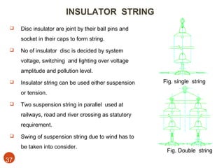
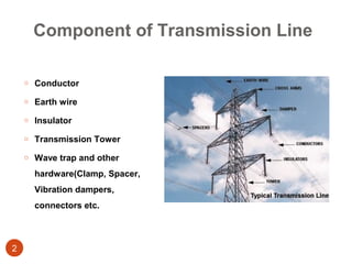
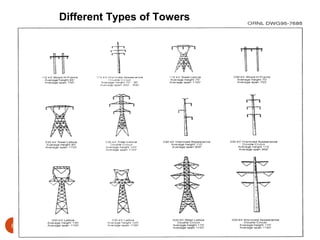
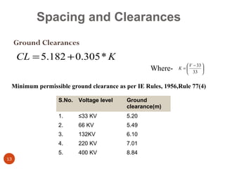
This document discusses the key components and design considerations for extra high voltage (EHV) AC transmission lines. It covers: 1. The main components of transmission lines including conductors, earth wires, insulators, towers, and hardware. 2. The design methodology which involves calculating loads from climatic conditions, reliability requirements, and safety factors before designing each component. 3. Factors involved in selecting the transmission voltage level based on the power level, line length, voltage regulation needs, and costs. 4. The types of transmission towers used for different line angles and situations like river crossings. 5. Design of the tower structure including height, base width, cross arm length based


