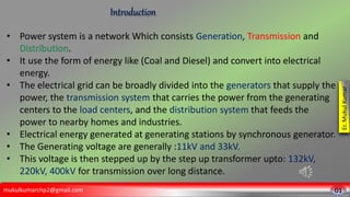
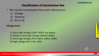
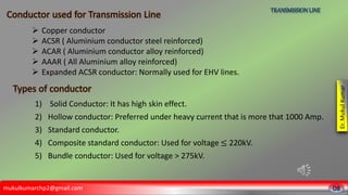
3. mukulkumarchp2@gmail.com
Er.
Mukul
Kumar
• Power system is a network Which consists Generation, Transmission and
.
• It use the form of energy like (Coal and Diesel) and convert into electrical
energy.
• The electrical grid can be broadly divided into the generators that supply the
power, the transmission system that carries the power from the generating
centers to the load centers, and the distribution system that feeds the
power to nearby homes and industries.
• Electrical energy generated at generating stations by synchronous generator.
• The Generating voltage are generally :11kV and 33kV.
• This voltage is then stepped up by the step up transformer upto: 132kV,
220kV, 400kV for transmission over long distance.
01
Introduction
4. mukulkumarchp2@gmail.com
Er.
Mukul
Kumar
02
Introduction
• Again this high voltages are brought down to sub-transmission level: 66kV
to large consumer and further stepped down for primary distribution:
33kV, 11kV.
• Electric power is the product of two quantities: current and voltage.
These two quantities can vary with respect to time (AC power) or can be
kept at constant levels (DC power).
5. mukulkumarchp2@gmail.com
Er.
Mukul
Kumar
03
Introduction
• In 1890, first hydroelectric plant was commissioned.
• In 1975, central government entered in the field of generation
through PSU (NTPC,..).
• In 1989, Power grid corporation of India was formed.
• In 1990, first HVDC bi-pole line was formed.
• In 1998, first 765kV line was erected.
• India is the third largest producer of electricity in the world.
• The national electric grid in India has an installed capacity of
410.3 GW as of 31 December 2022.
6. • In August 2006, Northern, Eastern, North-Eastern and Western Grids were
connected of form central grid.
• On 31st December 2013, Southern Grid was also connected to other 4 Grids in
synchronous mode.
mukulkumarchp2@gmail.com
Er.
Mukul
Kumar
04
Introduction
• Five Regional Grids
1. Northern
2. Eastern
3. North-Eastern
4. Western
5. Southern
Nation
7. mukulkumarchp2@gmail.com
Er.
Mukul
Kumar
05
Objective
• Cost of electric energy per unit (kWhr) must be minimized
• Rated voltage and frequency must be supplied to consumers.
• Reliable of power system as consumer demand must be
available.
• Effective protection system should be available.
• Generators must not lose synchronism under faulty conditions.
• Flexible power transfer has to be made available.
8. mukulkumarchp2@gmail.com
Er.
Mukul
Kumar
• A transmission line is a two-port network connecting a generating circuit
at the sending end to a load at the receiving end.
• Transmission line is a link or power carrier between two buses in the
network.
• Transmission line act as branch of network.
• Bus acts as node in the network.
• Transmission line are made of conducting material ( Al, Cu, Ag, Au)
• Transmission system consists of a network of overhead lines or in
densely populated areas, under ground cables.
• The lines are designed to transmit large power from point of generation
to the load side.
06
Transmission Line
9. mukulkumarchp2@gmail.com
Er.
Mukul
Kumar
06
• We classify transmission lines with reference to:
1) Voltage
2) Distance
3) AC or DC
TRANSMISSION LINE
1) Ultra high voltage (UHV) 765kV and above.
2) Modern extra high Voltage (MEHV) 400kV
3) Extra high voltage (EHV) 66kV, 132kV, 220kV
4) High voltage (HV) 11kV, 33kV
10. mukulkumarchp2@gmail.com
Er.
Mukul
Kumar
07
TRANSMISSION LINE
1) Long length transmission line (>320 KM)
2) Medium length transmission line ( 80-160KM)
3) Small length transmission line (<80KM)
The transmission line may be ac or dc depending upon the application.
1. Primary distribution 11kV, 33kV
3-phase 3-wire
2. Secondary distribution 415V, 220V
3-phase 4-wire/ 1-phase 2-wire
For India system tolerance provided for voltage distribution is 6% and for universal
system tolerance 5 %.
11. 1) Solid Conductor: It has high skin effect.
2) Hollow conductor: Preferred under heavy current that is more that 1000 Amp.
3) Standard conductor.
4) Composite standard conductor: Used for voltage ≤ 220kV.
5) Bundle conductor: Used for voltage > 275kV.
mukulkumarchp2@gmail.com
Er.
Mukul
Kumar
08
TRANSMISSION LINE
Copper conductor
ACSR ( Aluminium conductor steel reinforced)
ACAR ( Aluminium conductor alloy reinforced)
AAAR ( All Aluminium alloy reinforced)
Expanded ACSR conductor: Normally used for EHV lines.
12. mukulkumarchp2@gmail.com
Er.
Mukul
Kumar
Over head lines insulators provide the required insulation to the line conductor from each
other and from the supporting structures electrically. Most commonly used materials are
porcelain and toughened glass.
09
Introduction
• Pin type insulator: Pin type insulator operate satisfactory upto 25kV.
• Multipin type insulator: Operates upto 33kV.
• Suspension type insulator: a suspension insulator is designed to operate at 11 kV.
• Strain type insulator: Strain type insulator mechanically strong. It is used when
direction of transmission line changes across river crossing and at the dead end of
the transmission line.
• Shackle type: Shackle type insulator are used in low tension cable. These insulator
can be operated either horizontally or vertically.
13. When AC current flow the current near the surface of conductor and it is called as skin
effect.
Skin Depth is defined as the dept from the surface of conductor upto which current in
a conductor flow.
A network which has the same parameters as the actual transmission line is said to be
equivalent circuit to transmission line.
mukulkumarchp2@gmail.com
Er.
Mukul
Kumar
10
Skin effect
Equivalent circuit
Bundled conductor
One conductor is replace by a group of conductors kept at certain distance.
Corona
Electric field on surface of conductor is greater than dielectric strength than air around
the conductor imazes.
Due to corona there is hissing sound and purple glow around the conductor.
Due to light and sound the energy is dissipated called as corona loss.