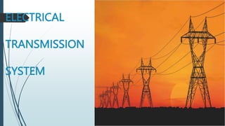
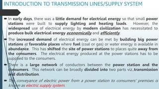
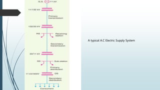
1. The document discusses electrical transmission systems, which convey electric power from power stations to consumers. It describes the key components of a typical electric supply system, including power stations, transmission lines, and distribution networks.
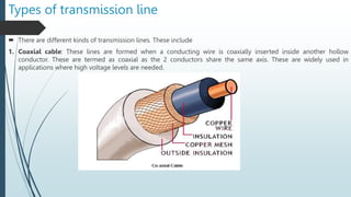
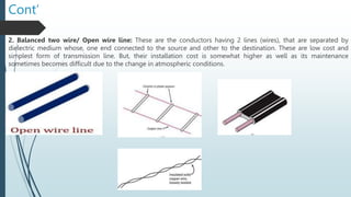
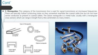
2. Transmission lines are conductors that transmit electric power over long distances from power stations to substations. Different types of transmission lines are discussed, including overhead lines, underground cables, and various conductor configurations.
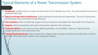
3. The document covers the classification of transmission lines based on voltage level, structure, and length. It also discusses the typical elements that make up a power transmission system and the electrical design of transmission lines, focusing on the resistance, inductance, and capacitance properties that determine their performance


![Cont’
5. Fiber Optic: This is a flexible, transparent fiber made by drawing glass (silica) or plastic to a diameter slightly
thicker than that of a human hair.[1] Optical fibers are used most often as a means to transmit light[a] between the two
ends of the fiber and find wide usage in fiber-optic communications, where they permit transmission over longer
distances and at higher bandwidths (data transfer rates) than electrical cables. Fibers are used instead of metal wires
because signals travel along them with less loss; in addition, fibers are immune to electromagnetic interference, a
problem from which metal wires suffer.](https://image.slidesharecdn.com/electricaltransmissionsystemnotes3a-240413123854-5660f30b/85/Electrical-Transmission-System-Notes-3a-pptx-10-320.jpg)


![Power system planning & operation [eceg 4410]](https://cdn.slidesharecdn.com/ss_thumbnails/powersystemplanningoperationeceg-4410-130607134359-phpapp01-thumbnail.jpg?width=640&height=640&fit=bounds)