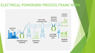
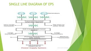
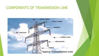
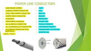
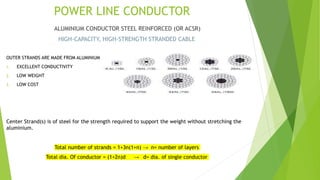
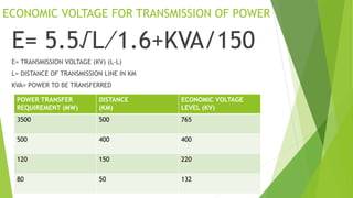
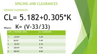
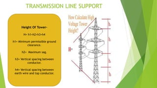
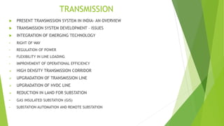
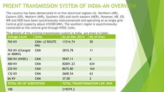
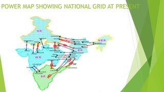
ELECTRICAL POWER TRANSMISSION
PRESENTED BY –
AMIT DEV PANDEY
ELECTRICAL POWERGRID PROCESS FRAME WORK
SINGLE LINE DIAGRAM OF EPS
COMPONENTS OF TRANSMISSION LINE
POWER LINE CONDUCTORS
1. HARD DRAWN COPPER
2. CADMIUM COPPER CONDUCTOR
3. STEEL CORE COPPER CONDUCTOR
4. COPPER WELD CONDUCTOR
5. ALUMINIUM
6. HARD DRAWN ALUMINIUM
7. ALL ALUMINIUM CONDUCTOR
8. ALL ALUMINIUM ALLOY CONDUCTOR
9. ALLUMINIUM CONDUCTOR STEEL
REINFORCED
(ACSR), (ACCC)
1. COST
2. LIFE
3. BRITTLE
4. WEIGHT
5. RESISTANCE
6. POWER LOSS
7. TENSILE STRENGTH
8. LOW SPECIFIC GRAVITY
9. TEMPREATURE CO-EFFICIENT
10. SHORTER SAG
POWER LINE CONDUCTOR
ALUMINIUM CONDUCTOR STEEL REINFORCED (OR ACSR)
HIGH-CAPACITY, HIGH-STRENGTH STRANDED CABLE
OUTER STRANDS ARE MADE FROM ALUMINIUM
1. EXCELLENT CONDUCTIVITY
2. LOW WEIGHT
3. LOW COST
Center Strand(s) is of steel for the strength required to support the weight without stretching the
aluminium.
Total number of strands = 1+3n(1+n) → n= number of layers
Total dia. Of conductor = (1+2n)d → d= dia. of single conductor
ECONOMIC VOLTAGE FOR TRANSMISSION OF POWER
E= 5.5√L⁄1.6+KVA/150
E= TRANSMISSION VOLTAGE (KV) (L-L)
L= DISTANCE OF TRANSMISSION LINE IN KM
KVA= POWER TO BE TRANSFERRED
POWER TRANSFER
REQUIREMENT (MW)
DISTANCE
(KM)
ECONOMIC VOLTAGE
LEVEL (KV)
3500 500 765
500 400 400
120 150 220
80 50 132
SPACING AND CLEARANCES
GROUND CLEARANCES-
CL= 5.182+0.305*K
Where- K= (V-33/33)
S.NO
.
VOLTAGE LEVEL G. CLEARANCE
1 ≤33 KV 5.20
2 66 KV 5.49
3 132 KV 6.10
4 220 KV 7.01
5 500 KV 8.84
SPACING BETWEEN CONDUCOR (Phases)-
1) VDE FORMULA
Spacing (cm)= 7.5√S+V²/2000 Where-
V= Voltage of system in KV
S= SAG in cm
2) Swedish formula
Spacing (cm)= 6.5√s+0.7*E Where-
E= Line voltage in KV
S= Sag in cm
3) French Formula= 8.0√S+L +E/1.5 Where-
E= Line voltage in KV
S= Sag in cm
L= Length of insulating string(cm)
VIBRATIONS ON CONDUCTORS
SPACERS AND DAMPERS
 Transmission lines are arranged in multi- conductors per phase.
 The spacer is accompanied for the purpose of maintaining
separation in conductors where as the damper absorbs the wind
vibration.
TRANSMISSION LINE SUPPORTS
FUNCTIONAL REQUIREMNT LOADING CASES
1. Voltage
2. Number of circuits
3. Type of conductor
4. Type of insulator
5. Future addition of new circuits
6. Tracing of transmission lines
7. Selection of tower sites
8. Selection of rigid points
9. Selection of height for each
tower
1. Dead load of tower
2. Dead load of conductors etc
3. Snow on conductor etc
4. Ice load on the tower itself
5. Erection & maintenance load
6. Wind load on tower
7. wind load on conductors etc.
8. conductor tensile forces
9. Earthquake forces
TRANSMISSION LINE SUPPORTS
MAIN REQUIREMENTS-
1. LOW COST
2. LONGER LIFE
3. ECONOMICAL TO
MAINTAIN
4. GROUND CLEARANCE
5. LIGHTER IN WEIGHT
6. HIGH MECHANICAL
STRENGTH
7. ACCESSIBLE
VOLTAGE LEVEL CLEARANCE TO
GROUND
Less than 66 KV 20 feet (6.1m)
66 KV to 132 KV 21 feet (6.4m)
132kv to 220kv 22 feet (6.7m)
Greater than 220kv 23 feet (7.0m)
MATERIAL TRANSMISSION LINE SUPPORTS
Tubular steel- In 2021 the first T-pylon, a new tubular T-shaped design, was
installed in united kingdom for a new power line Hinkley point C new power
station, carrying two high voltage 400KV power line.
Lattice- A lattice tower is a framework construction made of steel or
aluminium sections. Lattice towers are used for most common use for high
voltage transmission lines. Lattice tower are usually made of galvanized
steel. Aluminium is used for reduced weight, such as mountainous areas
where structure are placed by helicopter.
Wood- Wood is a material which is limited in use in high voltage
transmission. Because of the limited height of the available trees, the
maximum height of wood pylons is limited to approximately 30m (98feet).
Concrete- Concrete tower are generally used for low voltage.
TRANSMISSION LINE SUPPORT
 Type A Tower (Tangent Tower with suspension string)
Used on straight runs and up to 2° line diversion
 Type B Tower (Small angle tower with tension string)
Used for line deviation from 2° to 15°
 Type C Tower (Medium Angle tower with tension string )
Used for line deviation from 15° to 30°.
 Type D Tower (Large Angle lower with tension string )
Used for line deviation from 30° to 60°.
 Type E Tower (Dead end tower with tension string)
Used for termination and starting
 Special tower-
• Suspension tower (span≈ 1000 m)
Used for river crossing , Mountain, Crossing etc.
• Transposition tower
Used for transposition of tower.
TRANSMISSION LINE SUPPORT
Height Of Tower-
H= h1+h2+h3+h4
h1= Minimum permissible ground
clearance.
h2= Maximum sag.
h3= Vertical spacing between
conductor.
h4= Vertical spacing between
earth wire and top conductor.
TRANSMISSION
 PRESENT TRANSMISSION SYSTEM IN INDIA- AN OVERVIEW
 TRANSMISSION SYSTEM DEVELOPMENT – ISSUES
 INTEGRATION OF EMERGING TECHNOLOGY
• RIGHT OF WAY
• REGULATION OF POWER
• FLEXIBILITY IN LINE LOADING
• IMPROVEMENT OF OPERATIONAL EFFICIENCY
 HIGH DENSITY TRANSMISSION CORRIDOR
 UPGRADATION OF TRANSMISSION LINE
 UPGRADATION OF HVDC LINE
 REDUCTION IN LAND FOR SUBSTATION
• GAS INSULATED SUBSTATION (GIS)
• SUBSTATION AUTOMATION AND REMOTE SUBSTATION
PRSENT TRANSMISSION SYSTEM OF INDIA-AN OVERVIEW
The country has been demarcated in to five electrical regions viz. Northern (NR),
Eastern (ER), Western (WR), Southern (SR) and north eastern (NER). However, NR, ER,
WR and NER have been synchronously interconnected and operating at as single grid –
Central grid (capacity about 410300 MW). The southern region is asynchronously
connected to the central grid through HVDC Links.
The details of the existing transmission system in India are given in table-
Voltage Level Units As on Dec 2014 No of lines
765 KV CKM= (2 ROUTE
KM)
11514.74 50
765 KV (Charged
at 400KV)
CKM 2810.78 11
500 KV (HVDC) CKM 5947.11 6
400 KV CKM 82001.23 634
220 KV CKM 8675.80 164
132 KV CKM 2600.54 63
66 KV CKM 37.00 2
TOTAL NO OF SUBSTATION TOTAL TRANSFORMATION CAP. MVA
188 219579.2
POWER MAP SHOWING NATIONAL GRID AT PRESENT
TRANSMISSION SYSTEM DEVELOPMENT - ISSUES
However, Development o transmission system involves following issues;
 Minimization of right of way
 Protection of flora & fauna , wild life
 Creation of long distance high capacity transmission corridors to enable and
minimum cost per MW transfer as well as optimal transmission losses
 Minimum impact on environment
 Strengthening of national grid.
TRANSMISSION SYSTEM DEVELOPMENT - ISSUES
INTEGRATION OF EMERGING TECHNOLOGY
To meet the growing power demand of various region, power transfer capacity of the
inter-regional links is being enhanced continuously.
RIGHT OF WAY- The most notable and challenging issue the transmission sector is
facing today is the right of way (ROW). It is the need of the hour to develop high
intensity transmission corridor (MW PER METER ROW) In an environment friendly
manner including protection of flora and fauna.
REGULATION OF POWER- Another important aspect is the need toward regulation of power flow
due to wide variation in demand on day as well as seasonal basis and the draw pattern /shares of
the utilities from time to time.
FLEXIBILITY IN LINE LOADING- To handle more power as well as to optimize the use of
transmission corridor it is important to load the different lines in the corridor more or less
equally. To achieve this use of power electronic control devices like fixed and Thyristor controlled
series capacitors (TCSC) and similar other means is an effective method.
IMPROVEMENT OF OPERATIONAL EFFICIENCY- Power system is required to be operated at the rated
capacity with security, reliability and high availability. This can only be achieved through
reliability based on-line monitoring, repair and maintenance in advance and making forced
outage as zero.( with the help od EHV/UHV AC System, HVDC SYSTEM, Compact tower, mitigating
devices to address high short circuit level, intelligent grid etc.
HIGH DENSITY TRANSMISSION CORRIDOR – In order to optimize right of way, high density
transmission corridor (MW per meter ROW) either by increasing voltage level or current order or
both i.e. Increase in voltage and current are need to be developed.
VOLTAGE 132KV 220KV 400KV 765KV ±500KV ± 800KV 1200KV
ROW
meter(m)
27 35 46 64 52 70 90
Capacity
(MW)
Up-to
70-80
Up-to
160-170
Up-to
600-700
Up-to
2500-
3000
Up-to
2000-
2500
Up-to
6000-
6400
Up-to
6000-
8000
MW/M 3 5 15 45 48 90 90
UPGRADATION OF TRANSMISSION LINE- POWERGRID has successfully implemented upgrading of
200KV D/C Kishenpur-kishtwar line in J$K to 400KV S/C first time in India. It has resulted in
increase of power transfer intensity of the transmission corridor with marginal increase in
ROW (from 35m to 37m) but far less than standard 400KV line (46m).
UPGRADATION OF HVDC TERMINAL- POWERGRID has seamlessly upgraded ±500KV Talcher (ER)-
Kolar(SR) HVDC terminal from 2000MW to 2500MW without changing of equipment. That has
been achieved with enhanced cooling of transformer and smoothing reactor with meager cost.
REDUCTION IN LAND FOR SUBSTATION-
GAS INSULATED SUBSTATION – With scare land availability there is a growing need for reduction
of land use for setting up of transmission system, particularly in metros, hilly and other urban
areas. POWERGRID has established state –of-the-art gas insulated substation (GIS), which
require less space (about 80% reduction) i.e. 5-6 acres as compared to conventional
substation which require generally requires 30-40 acre area. Powergrid has already
commissioned 400/200KV GIS at maharanibagh in delhi.
SUBSTATION AUTOMATION AND REMOTE OPERATION- There is a growing need for judicious use
of skilled manpower and their redeployment in areas requiring more attention. Toward
achieving this goal, POWERGRID Established its first remote controlled 400KV substation at
bhiwadi, remotely controlled from ballabgargh substation.
CURRENT TRANSMISSION MARKET STRUCTURE
Ministry of power (MOP)
(Perspective planning, policy formation, processing of projects for investment decision, monitoring of the
implementation of power projects, training and manpower development and the administration and enactment
of legislation in regards to power generation, transmission and distribution)
Central Electricity Authority of India (CEA)
(Advises the government on matters relating to the national electricity policy and formulates short-term and
perspective plans for the development of electricity system)
Central Electricity Regulatory Commission
(CERC)
(Regulate tariff, formulates regarding subsides, and
promotion of efficient and environmentally benign
policies at central level)
State Electricity Regulation Commission (SERC)
(Regulates tariff; formulates policies regarding subsides,
and promotion of efficient and environmentally benign
policies at state level)
Central Transmission Utility
(CTU)
(Ensures development of an
efficient, coordinated and
economical system of inter-state
transmission lines and undertakes
inter-state transmission
Private/PPP
( Develops transmission lines on
Boo model and charges for
wheeling electricity with in the
tariffs specified by CERC/SERC)
State Transmission Utility
(STU)
(Ensures development of an
efficient, coordinated and
economical system of intra-state
transmission lines and undertakes
intra-state transmission)
EVOLUTION OF TRANSMISSION SECTOR
Indian power sector remained closed to private investments till 1991. Power generation
was opened up for private participation in 1991. The electricity (Amendment) Act, 1998,
defined transmission as a separate activity and led to a creation of the CTU (currently
PGCIL) and STU. The Regulatory commission Act 1998, mandate the setting up of an
independent regulatory mechanism at the central (CERC) and the state level (SERC).
Electricity act 2003 further rationalized the approach for privatization of the power sector.
For transmission sector, some project were to be earmarked for tariff based competitive
bidding (TBCB). CERCs AND SERCs would grant licenses for building, maintaining and
operating transmission lines. Both, private players and public utilities (PGCIL, STUs) could
participate in the bidding individually or through joint ventures.
The transmission network plan was created detailing out new projects, up-gradation of
existing lines and the required specification. A multi stake holder empowered committee
would identify projects to be developed and would reward projects after the evaluation of
bids. CEA would monitor the progress of projects as per CERCs guidelines.
National Tariff policy 2006 introduced mandatory tariff based competitive bidding (TBCB)
for all transmission projects with the objective of promoting competitive procurement of
transmission service, encouraging greater investment by private players in the transmission
sector and increasing transparency & fairness in the process. Many private players, ranging
from power generation companies like Adani, GMR, etc to EPC and infrastructure
companies like KEC. Isolux, etc are entering the sector. However, progress in the sector is
hampered by various challenges.
MAJOR MILESTONES IN INDIA TRANSMISSION SECTOR
1991
Electricity Laws
(Amendment)
Act
. Private
participation
allowed
generation
. SEBs to be
responsible for
transmission
and distribution
of power
1998
Electricity Laws
(Amendment) Act
. Private
participation
enabled in
transmission
. CTU and STUs
set up
Electricity
Regulatory
Commission Act
. CERC & SERCs
formed
. Regulator to
protect &promote
consumer interest
,fair, competition
and transparency
2003
The Electricity
Act
. Replaced the
earlier laws,
aiming to enable
reforms &
restructure power
sector
. National
Electricity policy
brought out,
mandatory
creation of SERCs,
emphasis on rural
electrification
open access in
transmission and
distribution
. Introduced a non
discriminatory
open access in the
transmission
2006
National tariff
policy
. Mandatory
competitive
bidding of all
transmission
project after Jan
2011
. Framework for
determining
tariffs and rate
of returns for
projects under
generation
transmission as
well as
distribution
2011
National
tariff policy
(Amendment)
Exemption to
intra-state
transmission
sector from
mandatory
competitive
bidding up to
5th Jan 2013
Exemption of
select
experimental
work/urgent/
compressed
time schedule
work from
tariff based
competitive
bidding
ELECTRICAL POWER TRANSMISSION-3.pptx

ELECTRICAL POWER TRANSMISSION-3.pptx

  • 1.
  • 2.
  • 3.
  • 4.
  • 5.
    POWER LINE CONDUCTORS 1.HARD DRAWN COPPER 2. CADMIUM COPPER CONDUCTOR 3. STEEL CORE COPPER CONDUCTOR 4. COPPER WELD CONDUCTOR 5. ALUMINIUM 6. HARD DRAWN ALUMINIUM 7. ALL ALUMINIUM CONDUCTOR 8. ALL ALUMINIUM ALLOY CONDUCTOR 9. ALLUMINIUM CONDUCTOR STEEL REINFORCED (ACSR), (ACCC) 1. COST 2. LIFE 3. BRITTLE 4. WEIGHT 5. RESISTANCE 6. POWER LOSS 7. TENSILE STRENGTH 8. LOW SPECIFIC GRAVITY 9. TEMPREATURE CO-EFFICIENT 10. SHORTER SAG
  • 6.
    POWER LINE CONDUCTOR ALUMINIUMCONDUCTOR STEEL REINFORCED (OR ACSR) HIGH-CAPACITY, HIGH-STRENGTH STRANDED CABLE OUTER STRANDS ARE MADE FROM ALUMINIUM 1. EXCELLENT CONDUCTIVITY 2. LOW WEIGHT 3. LOW COST Center Strand(s) is of steel for the strength required to support the weight without stretching the aluminium. Total number of strands = 1+3n(1+n) → n= number of layers Total dia. Of conductor = (1+2n)d → d= dia. of single conductor
  • 7.
    ECONOMIC VOLTAGE FORTRANSMISSION OF POWER E= 5.5√L⁄1.6+KVA/150 E= TRANSMISSION VOLTAGE (KV) (L-L) L= DISTANCE OF TRANSMISSION LINE IN KM KVA= POWER TO BE TRANSFERRED POWER TRANSFER REQUIREMENT (MW) DISTANCE (KM) ECONOMIC VOLTAGE LEVEL (KV) 3500 500 765 500 400 400 120 150 220 80 50 132
  • 8.
    SPACING AND CLEARANCES GROUNDCLEARANCES- CL= 5.182+0.305*K Where- K= (V-33/33) S.NO . VOLTAGE LEVEL G. CLEARANCE 1 ≤33 KV 5.20 2 66 KV 5.49 3 132 KV 6.10 4 220 KV 7.01 5 500 KV 8.84
  • 9.
    SPACING BETWEEN CONDUCOR(Phases)- 1) VDE FORMULA Spacing (cm)= 7.5√S+V²/2000 Where- V= Voltage of system in KV S= SAG in cm 2) Swedish formula Spacing (cm)= 6.5√s+0.7*E Where- E= Line voltage in KV S= Sag in cm 3) French Formula= 8.0√S+L +E/1.5 Where- E= Line voltage in KV S= Sag in cm L= Length of insulating string(cm)
  • 10.
    VIBRATIONS ON CONDUCTORS SPACERSAND DAMPERS  Transmission lines are arranged in multi- conductors per phase.  The spacer is accompanied for the purpose of maintaining separation in conductors where as the damper absorbs the wind vibration.
  • 11.
    TRANSMISSION LINE SUPPORTS FUNCTIONALREQUIREMNT LOADING CASES 1. Voltage 2. Number of circuits 3. Type of conductor 4. Type of insulator 5. Future addition of new circuits 6. Tracing of transmission lines 7. Selection of tower sites 8. Selection of rigid points 9. Selection of height for each tower 1. Dead load of tower 2. Dead load of conductors etc 3. Snow on conductor etc 4. Ice load on the tower itself 5. Erection & maintenance load 6. Wind load on tower 7. wind load on conductors etc. 8. conductor tensile forces 9. Earthquake forces
  • 12.
    TRANSMISSION LINE SUPPORTS MAINREQUIREMENTS- 1. LOW COST 2. LONGER LIFE 3. ECONOMICAL TO MAINTAIN 4. GROUND CLEARANCE 5. LIGHTER IN WEIGHT 6. HIGH MECHANICAL STRENGTH 7. ACCESSIBLE VOLTAGE LEVEL CLEARANCE TO GROUND Less than 66 KV 20 feet (6.1m) 66 KV to 132 KV 21 feet (6.4m) 132kv to 220kv 22 feet (6.7m) Greater than 220kv 23 feet (7.0m)
  • 13.
    MATERIAL TRANSMISSION LINESUPPORTS Tubular steel- In 2021 the first T-pylon, a new tubular T-shaped design, was installed in united kingdom for a new power line Hinkley point C new power station, carrying two high voltage 400KV power line. Lattice- A lattice tower is a framework construction made of steel or aluminium sections. Lattice towers are used for most common use for high voltage transmission lines. Lattice tower are usually made of galvanized steel. Aluminium is used for reduced weight, such as mountainous areas where structure are placed by helicopter. Wood- Wood is a material which is limited in use in high voltage transmission. Because of the limited height of the available trees, the maximum height of wood pylons is limited to approximately 30m (98feet). Concrete- Concrete tower are generally used for low voltage.
  • 14.
    TRANSMISSION LINE SUPPORT Type A Tower (Tangent Tower with suspension string) Used on straight runs and up to 2° line diversion  Type B Tower (Small angle tower with tension string) Used for line deviation from 2° to 15°  Type C Tower (Medium Angle tower with tension string ) Used for line deviation from 15° to 30°.  Type D Tower (Large Angle lower with tension string ) Used for line deviation from 30° to 60°.  Type E Tower (Dead end tower with tension string) Used for termination and starting  Special tower- • Suspension tower (span≈ 1000 m) Used for river crossing , Mountain, Crossing etc. • Transposition tower Used for transposition of tower.
  • 15.
    TRANSMISSION LINE SUPPORT HeightOf Tower- H= h1+h2+h3+h4 h1= Minimum permissible ground clearance. h2= Maximum sag. h3= Vertical spacing between conductor. h4= Vertical spacing between earth wire and top conductor.
  • 16.
    TRANSMISSION  PRESENT TRANSMISSIONSYSTEM IN INDIA- AN OVERVIEW  TRANSMISSION SYSTEM DEVELOPMENT – ISSUES  INTEGRATION OF EMERGING TECHNOLOGY • RIGHT OF WAY • REGULATION OF POWER • FLEXIBILITY IN LINE LOADING • IMPROVEMENT OF OPERATIONAL EFFICIENCY  HIGH DENSITY TRANSMISSION CORRIDOR  UPGRADATION OF TRANSMISSION LINE  UPGRADATION OF HVDC LINE  REDUCTION IN LAND FOR SUBSTATION • GAS INSULATED SUBSTATION (GIS) • SUBSTATION AUTOMATION AND REMOTE SUBSTATION
  • 17.
    PRSENT TRANSMISSION SYSTEMOF INDIA-AN OVERVIEW The country has been demarcated in to five electrical regions viz. Northern (NR), Eastern (ER), Western (WR), Southern (SR) and north eastern (NER). However, NR, ER, WR and NER have been synchronously interconnected and operating at as single grid – Central grid (capacity about 410300 MW). The southern region is asynchronously connected to the central grid through HVDC Links. The details of the existing transmission system in India are given in table- Voltage Level Units As on Dec 2014 No of lines 765 KV CKM= (2 ROUTE KM) 11514.74 50 765 KV (Charged at 400KV) CKM 2810.78 11 500 KV (HVDC) CKM 5947.11 6 400 KV CKM 82001.23 634 220 KV CKM 8675.80 164 132 KV CKM 2600.54 63 66 KV CKM 37.00 2 TOTAL NO OF SUBSTATION TOTAL TRANSFORMATION CAP. MVA 188 219579.2
  • 18.
    POWER MAP SHOWINGNATIONAL GRID AT PRESENT
  • 19.
    TRANSMISSION SYSTEM DEVELOPMENT- ISSUES However, Development o transmission system involves following issues;  Minimization of right of way  Protection of flora & fauna , wild life  Creation of long distance high capacity transmission corridors to enable and minimum cost per MW transfer as well as optimal transmission losses  Minimum impact on environment  Strengthening of national grid. TRANSMISSION SYSTEM DEVELOPMENT - ISSUES INTEGRATION OF EMERGING TECHNOLOGY To meet the growing power demand of various region, power transfer capacity of the inter-regional links is being enhanced continuously. RIGHT OF WAY- The most notable and challenging issue the transmission sector is facing today is the right of way (ROW). It is the need of the hour to develop high intensity transmission corridor (MW PER METER ROW) In an environment friendly manner including protection of flora and fauna.
  • 20.
    REGULATION OF POWER-Another important aspect is the need toward regulation of power flow due to wide variation in demand on day as well as seasonal basis and the draw pattern /shares of the utilities from time to time. FLEXIBILITY IN LINE LOADING- To handle more power as well as to optimize the use of transmission corridor it is important to load the different lines in the corridor more or less equally. To achieve this use of power electronic control devices like fixed and Thyristor controlled series capacitors (TCSC) and similar other means is an effective method. IMPROVEMENT OF OPERATIONAL EFFICIENCY- Power system is required to be operated at the rated capacity with security, reliability and high availability. This can only be achieved through reliability based on-line monitoring, repair and maintenance in advance and making forced outage as zero.( with the help od EHV/UHV AC System, HVDC SYSTEM, Compact tower, mitigating devices to address high short circuit level, intelligent grid etc. HIGH DENSITY TRANSMISSION CORRIDOR – In order to optimize right of way, high density transmission corridor (MW per meter ROW) either by increasing voltage level or current order or both i.e. Increase in voltage and current are need to be developed. VOLTAGE 132KV 220KV 400KV 765KV ±500KV ± 800KV 1200KV ROW meter(m) 27 35 46 64 52 70 90 Capacity (MW) Up-to 70-80 Up-to 160-170 Up-to 600-700 Up-to 2500- 3000 Up-to 2000- 2500 Up-to 6000- 6400 Up-to 6000- 8000 MW/M 3 5 15 45 48 90 90
  • 21.
    UPGRADATION OF TRANSMISSIONLINE- POWERGRID has successfully implemented upgrading of 200KV D/C Kishenpur-kishtwar line in J$K to 400KV S/C first time in India. It has resulted in increase of power transfer intensity of the transmission corridor with marginal increase in ROW (from 35m to 37m) but far less than standard 400KV line (46m). UPGRADATION OF HVDC TERMINAL- POWERGRID has seamlessly upgraded ±500KV Talcher (ER)- Kolar(SR) HVDC terminal from 2000MW to 2500MW without changing of equipment. That has been achieved with enhanced cooling of transformer and smoothing reactor with meager cost. REDUCTION IN LAND FOR SUBSTATION- GAS INSULATED SUBSTATION – With scare land availability there is a growing need for reduction of land use for setting up of transmission system, particularly in metros, hilly and other urban areas. POWERGRID has established state –of-the-art gas insulated substation (GIS), which require less space (about 80% reduction) i.e. 5-6 acres as compared to conventional substation which require generally requires 30-40 acre area. Powergrid has already commissioned 400/200KV GIS at maharanibagh in delhi. SUBSTATION AUTOMATION AND REMOTE OPERATION- There is a growing need for judicious use of skilled manpower and their redeployment in areas requiring more attention. Toward achieving this goal, POWERGRID Established its first remote controlled 400KV substation at bhiwadi, remotely controlled from ballabgargh substation.
  • 22.
    CURRENT TRANSMISSION MARKETSTRUCTURE Ministry of power (MOP) (Perspective planning, policy formation, processing of projects for investment decision, monitoring of the implementation of power projects, training and manpower development and the administration and enactment of legislation in regards to power generation, transmission and distribution) Central Electricity Authority of India (CEA) (Advises the government on matters relating to the national electricity policy and formulates short-term and perspective plans for the development of electricity system) Central Electricity Regulatory Commission (CERC) (Regulate tariff, formulates regarding subsides, and promotion of efficient and environmentally benign policies at central level) State Electricity Regulation Commission (SERC) (Regulates tariff; formulates policies regarding subsides, and promotion of efficient and environmentally benign policies at state level) Central Transmission Utility (CTU) (Ensures development of an efficient, coordinated and economical system of inter-state transmission lines and undertakes inter-state transmission Private/PPP ( Develops transmission lines on Boo model and charges for wheeling electricity with in the tariffs specified by CERC/SERC) State Transmission Utility (STU) (Ensures development of an efficient, coordinated and economical system of intra-state transmission lines and undertakes intra-state transmission)
  • 23.
    EVOLUTION OF TRANSMISSIONSECTOR Indian power sector remained closed to private investments till 1991. Power generation was opened up for private participation in 1991. The electricity (Amendment) Act, 1998, defined transmission as a separate activity and led to a creation of the CTU (currently PGCIL) and STU. The Regulatory commission Act 1998, mandate the setting up of an independent regulatory mechanism at the central (CERC) and the state level (SERC). Electricity act 2003 further rationalized the approach for privatization of the power sector. For transmission sector, some project were to be earmarked for tariff based competitive bidding (TBCB). CERCs AND SERCs would grant licenses for building, maintaining and operating transmission lines. Both, private players and public utilities (PGCIL, STUs) could participate in the bidding individually or through joint ventures. The transmission network plan was created detailing out new projects, up-gradation of existing lines and the required specification. A multi stake holder empowered committee would identify projects to be developed and would reward projects after the evaluation of bids. CEA would monitor the progress of projects as per CERCs guidelines. National Tariff policy 2006 introduced mandatory tariff based competitive bidding (TBCB) for all transmission projects with the objective of promoting competitive procurement of transmission service, encouraging greater investment by private players in the transmission sector and increasing transparency & fairness in the process. Many private players, ranging from power generation companies like Adani, GMR, etc to EPC and infrastructure companies like KEC. Isolux, etc are entering the sector. However, progress in the sector is hampered by various challenges.
  • 24.
    MAJOR MILESTONES ININDIA TRANSMISSION SECTOR 1991 Electricity Laws (Amendment) Act . Private participation allowed generation . SEBs to be responsible for transmission and distribution of power 1998 Electricity Laws (Amendment) Act . Private participation enabled in transmission . CTU and STUs set up Electricity Regulatory Commission Act . CERC & SERCs formed . Regulator to protect &promote consumer interest ,fair, competition and transparency 2003 The Electricity Act . Replaced the earlier laws, aiming to enable reforms & restructure power sector . National Electricity policy brought out, mandatory creation of SERCs, emphasis on rural electrification open access in transmission and distribution . Introduced a non discriminatory open access in the transmission 2006 National tariff policy . Mandatory competitive bidding of all transmission project after Jan 2011 . Framework for determining tariffs and rate of returns for projects under generation transmission as well as distribution 2011 National tariff policy (Amendment) Exemption to intra-state transmission sector from mandatory competitive bidding up to 5th Jan 2013 Exemption of select experimental work/urgent/ compressed time schedule work from tariff based competitive bidding