Download to read offline
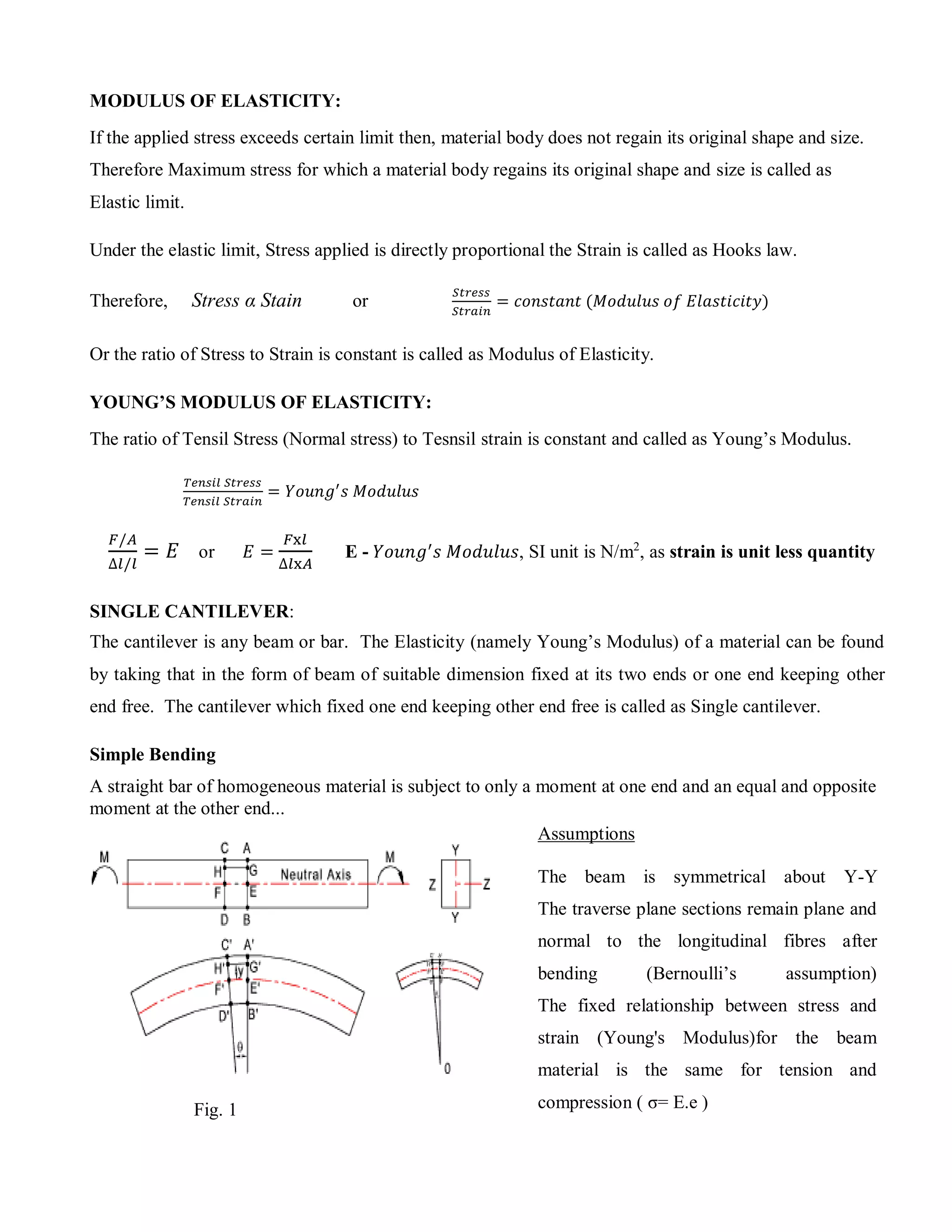
![Consider two section very close together (AB and CD) as shown in fig. 1. After bending, the sections
will be at A′B′ and C′D′ and are no longer parallel. AC will have extended to A′C′ and BD will have
compressed to B′D′. The line EF will be located such that it will not change in length. This surface is
called neutral surface and its intersection with Z_Z is called the neutral axis
The development lines A'B' and C'D' are intersecting at a point O at an angle of θ radians and the radius
of E′F′ = R
Let y be the distance (E'G') of any layer H'G' originally parallel to EF.
Then H′G′/E'F' =(R+y)θ /R θ = (R+y)/R
And the strain e at layer H'G' =
e = (H'G'- HG) / HG = (H'G'- HG) / EF = [(R+y)θ - R θ] /R θ = y /R
The accepted relationship between stress and strain is σ = E.e Therefore
σ = E.e = E. y /R
σ / E = y / R
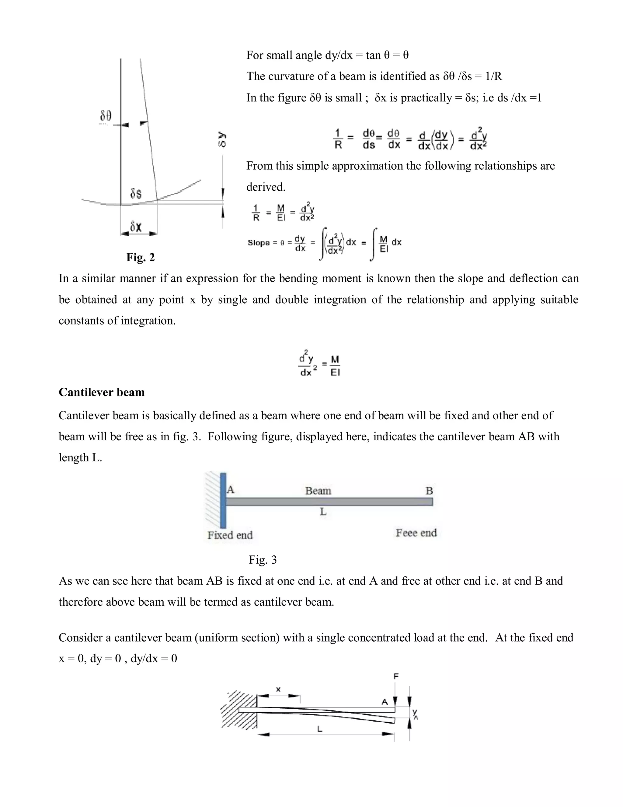
From the above the following important simple beam bending relationship results
A simple beam subject to bending generates a maximum stress at the surface furthest away from the
neutral axis. Then tensile stress on the surface CA is given by.
σmax = ymax. M / I
Deflection of Beams:
A beam is basically defined as one structural member used to bear the different loads. In structure, beam
helps to bear the load and one must have been noted that, there will not be any structure without beams.
Below is shown the arc of the neutral axis of a beam subject to bending. Beam is usually subjected with
vertical load, shear load and also sometimes with horizontal load. We must have to note it here that cross
section of a beam will be quite smaller as compared to its length.
There are different types of beam used to perform the experiment of elasticity of material one of them is
Single cantilever method](https://image.slidesharecdn.com/youngsmodulusbysinglecantilevermethod-201106104306/75/Young-s-modulus-by-single-cantilever-method-3-2048.jpg)

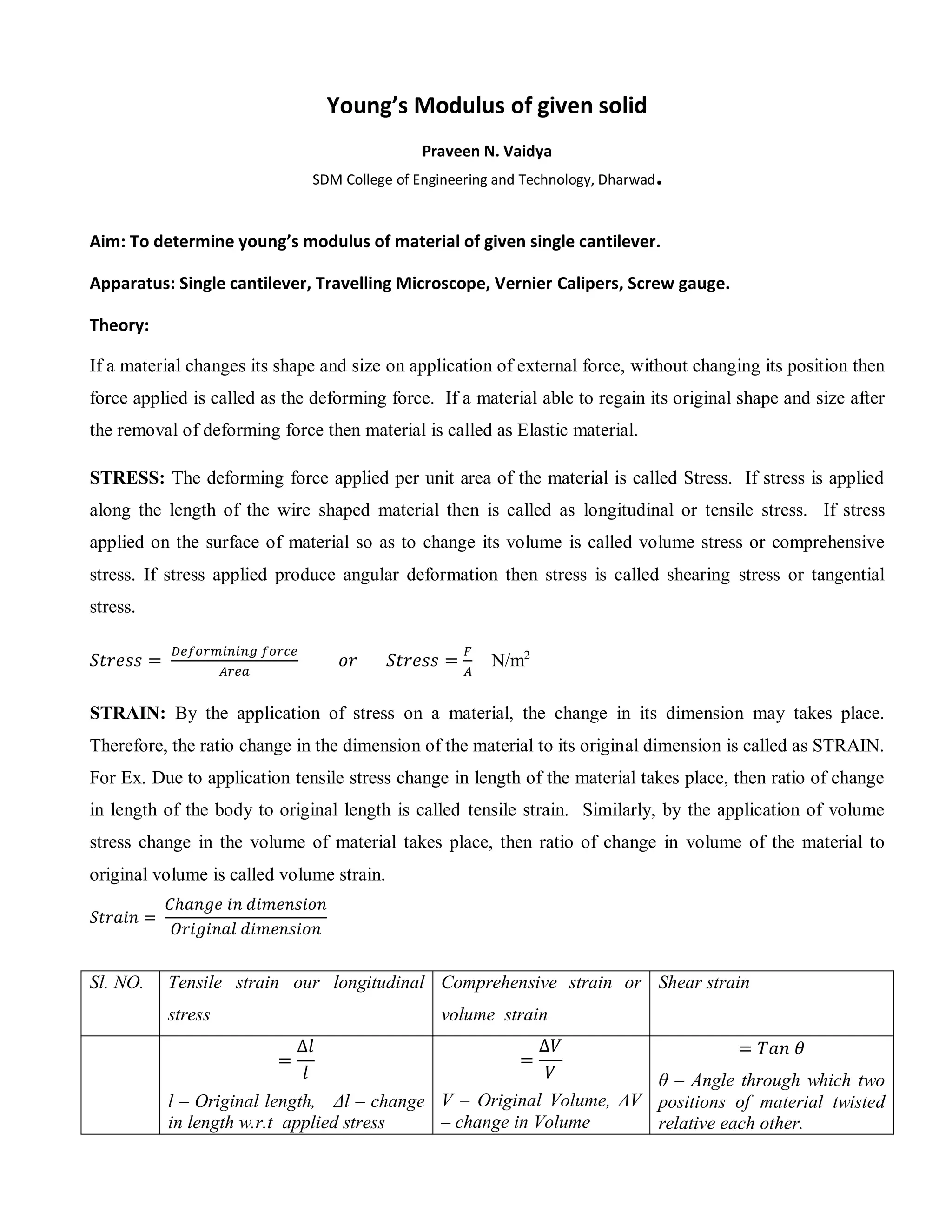
The document outlines a laboratory procedure for determining Young's modulus of a material using a single cantilever setup. It explains key concepts such as stress, strain, and the relationship between them as described by Hooke's law, alongside theoretical background on beam bending and deflection. The methodology includes measuring dimensions and weight-induced deflection while utilizing equipment like vernier calipers and screw gauges.