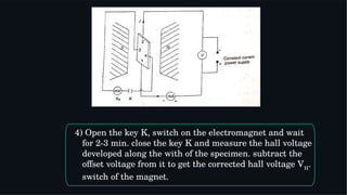
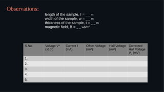
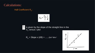
2. To study the hall effect and hence to determine the hall
coefficient for the given sample of semiconductor.
Aim:
Apparatus:
A thin semi-conductor rectangular slab, a constant current
power supply (0-20mA), an electromagnet, hall effect set up,
a digital milliammeter and connecting wires.
3. If a current carrying conductor placed in a perpendicular magnetic
field, a potential difference will generate in the conductor which is
perpendicular to both magnetic field and current. this phenomenon is
called Hall Effect. in solid state physics, hall effect is an important tool
to characterize the materials especially semiconductors. it directly
determines both the sign and density of charge carriers in a given
sample.
If the magnetic field is applied along negative z-axis, the lorentz
force moves the charge carriers (say electrons) toward the y-direction.
this results in accumulation of charge carriers at the top edge of the
sample. this set up a transverse electric field in the sample. this
develop a potential difference along y-axis is known as hall
voltage VH and this effect is called hall effect.
Theory:
4. A current is made to flow through the sample material and the
voltage difference between its top and bottom is measured using a volt-
meter. When the applied magnetic field B=0,the voltage difference will
be zero.
Suppose the semi-conductor specimen slab of length l, width w, and
thickness t.
The hall field is given by,
EH
= RH
jB where j= ( I / wt ) is the current
density and B is the applied magnetic field.
RH
is the hall coefficient and is given by,
5. As wEH
is equal to the Hall voltage VH
,
the Hall’s coefficiently RH
is given by,
6. Formula Used:
where,
RH
= hall coefficient
VH
= hall voltage
I = sample current
B = magnetic field
t = thickness of probe
7. Procedure:
1) Place the semiconductor sample at the centre between
the pole pieces of the electromagnet with the help of a
stand such that the magnetic field is perpendicular to
the face of the sample, B is along the thickness of the
sample. switch on the constant current supply. The
current flows along the length of the specimen.
2) Note down the current I through the sample and the
voltage V* across it.
3) Close the key K. the voltage appearing along the width
of the sample is called offset voltage. note it down.
8. 4) Open the key K, switch on the electromagnet and wait
for 2-3 min. close the key K and measure the hall voltage
developed along the with of the specimen. subtract the
offset voltage from it to get the corrected hall voltage VH
.
switch of the magnet.
9. 5) Increase the current through the sample in small steps
and repeat the process to take at least 6-7 observations.
Remember that while measuring V, magnetic field
should remain off . It should be switched on only for
measuring VH
.
6) Measure the magnetic field strength B with the help of
a gauss meter. convert it to Weber/m2
.
7) Measure the length, width and thickness of the
specimen with the help of vernier callipers and screw
gauge.
8) Plot the graph for I along x-axis and VH
along y-axis.
10. Observations:
length of the sample, I = _ _ m
width of the sample, w = _ _ m
thickness of the sample, t = _ _ m
magnetic field, B = _ _ wb/m2
S.No. Voltage V*
(x103
)
Current I
(mA)
Offset Voltage
(mV)
Hall Voltage
(mV)
Corrected
Hall Voltage
VH
(mV)
1.
2.
3.
4.
5.
11. Calculations:
is given by the slope of the straight line in the
VH
versus I plot
RH
= Slope x (t/B) = ......Ωmm3
Wm-1
Hall Coefficient RH
:
13. Precautions and Sources of error:
1) The magnetic field should be measured carefully.
2) Adjust the distance between the poles of the
magnet nearly 1 cm, then only the gauss meter
shows correct reading.
3) Electromagnet power supply should be connected
to a 3 pin main socket having good earth
connection.
4) The current through the sample should not be
large enough to cause heating.