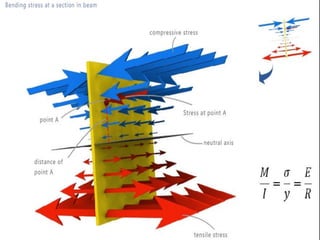
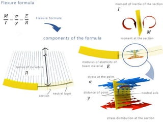
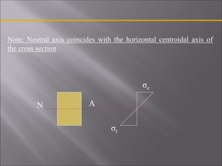
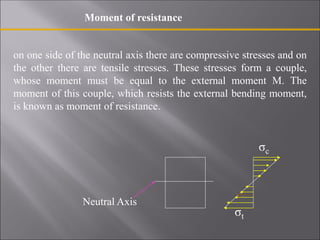
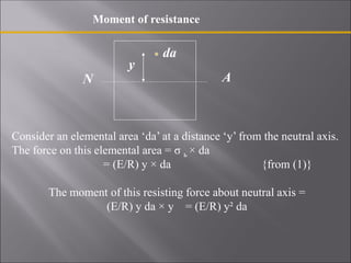
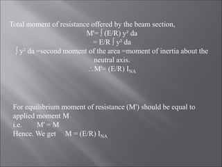
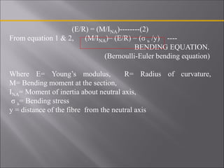
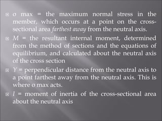
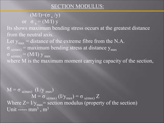
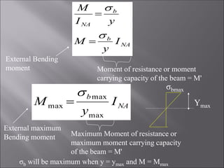
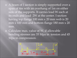
SlideShare a Scribd company logo
By
Prof. Ramesh R. Rajguru
Learning Outcomes L20
Bending Stresses
 In this module we will determine the stress in a
beam caused by bending.
 How to find the variation of the shear and
moment in these members.
 Then once the internal moment is determined,
the maximum bending stress can be calculated.
3.1 Bending stresses:
Theory of pure Bending, Assumptions, Flexural formula for straight beams, moment of
resistance, bending stress distribution, Section modulus, beams of uniform strength.
3.2 Direct & Bending Stresses:
Combined stresses, Eccentricity, Stress distribution, Core /kernel of Section.
3.3 Shear Stresses:
Distribution of shear stresses for the section of beam.
Module 3
Here is an example of where combined
axial and bending stress can occur.
Beams are important structural members used in
building construction. Their design is often based
upon their ability to resist bending stress.
Note the distortion of the lines due to bending of this rubber bar. The top line
stretches, the bottom line compresses, and the center line remains the same
length. Furthermore the vertical lines rotate and yet remain straight.
This wood specimen failed in bending due to its fibers being
crushed at its top and torn apart at its bottom.
BENDING STRESSES IN BEAMS
Beams are subjected to bending moment and shearing forces
which vary from section to section. To resist the bending
moment and shearing force, the beam section develops
stresses.
Bending is usually associated with shear. However, for
simplicity we neglect effect of shear and consider moment
alone ( this is true when the maximum bending moment is
considered---- shear is ZERO) to find the stresses due to
bending. Such a theory wherein stresses due to bending alone
is considered is known as PURE BENDING or SIMPLE
BENDING theory.
Example of pure bending
W W
SFD
-
+
a a
A B
VA= W VB= W
C D
BMD
Wa Wa
+
Pure bending
between C & D
BENDING ACTION:
Sagging
M
NEUTRALAXIS
NEUT
RALLAY
ER
σc
Neutral Axis
σt
Hogging
σc
Neutral Axis
σt
Neutral layer
BENDING ACTION
•Sagging-> Fibres below the neutral axis (NA) get stretched -> Fibres
are under tension
•Fibres above the NA get compressed -> Fibres are in compression
•Hogging -> Vice-versa
•In between there is a fibre or layer which neither undergoes tension
nor compression. This layer is called Neutral Layer (stresses are
zero).
•The trace of this layer on the c/s is called the Neutral Axis.
Assumptions made in Pure bending theory
1) The beam is initially straight and every layer is free to
expand or contract.
2) The material is homogenous and isotropic.
3) Young’s modulus (E) is same in both tension and
compression.
4) Stresses are within the elastic limit.
5) The radius of curvature of the beam is very large in
comparison to the depth of the beam.
6) A transverse section of the beam which is plane before bending
will remain plane even after bending.
7) Stress is purely longitudinal.
DERIVATION OF PURE BENDING EQUATION
Relationship between bending stress and radius of curvature.
PART I:
Consider the beam section of length “dx” subjected to pure
bending. After bending the fibre AB is shortened in length,
whereas the fibre CD is increased in length.
In b/w there is a fibre (EF) which is neither shortened in length
nor increased in length (Neutral Layer).
Let the radius of the fibre E'F′ be R . Let us select one more fibre
GH at a distance of ‘y’ from the fibre EF as shown in the fig.
EF= E'F′ = dx = R dθ
The initial length of fibre GH equals R dθ
After bending the new length of GH equals
G'H′= (R+y) dθ
= R dθ + y dθ
Change in length of fibre GH = (R dθ + y dθ) - R dθ = y dθ
Therefore the strain in fibre GH
Є= change in length / original length= y dθ/ R dθ
Є = y/R
If σ ь is the bending stress and E is the Young’s modulus of the material,
then strain
Є = σ ь/E
σ ь /E = y/R => σ ь = (E/R) y---------(1)
σ ь = (E/R) y => i.e. bending stress in any fibre is proportional to the
distance of the fibre (y) from the neutral axis and hence maximum
bending stress occurs at the farthest fibre from the neutral axis.
Note: Neutral axis coincides with the horizontal centroidal axis of
the cross section
N A
σc
σt
on one side of the neutral axis there are compressive stresses and on
the other there are tensile stresses. These stresses form a couple,
whose moment must be equal to the external moment M. The
moment of this couple, which resists the external bending moment,
is known as moment of resistance.
Moment of resistance
σc
Neutral Axis
σt
Moment of resistance
Consider an elemental area ‘da’ at a distance ‘y’ from the neutral axis.
The force on this elemental area = σ ь × da
= (E/R) y × da {from (1)}
The moment of this resisting force about neutral axis =
(E/R) y da × y = (E/R) y² da
da
y
N A
Total moment of resistance offered by the beam section,
M'=  (E/R) y² da
= E/R  y² da
 y² da =second moment of the area =moment of inertia about the
neutral axis.
M'= (E/R) INA
For equilibrium moment of resistance (M') should be equal to
applied moment M
i.e. M' = M
Hence. We get M = (E/R) INA
(E/R) = (M/INA)--------(2)
From equation 1 & 2, (M/INA)= (E/R) = (σ ь /y) ----
BENDING EQUATION.
(Bernoulli-Euler bending equation)
Where E= Young’s modulus, R= Radius of curvature,
M= Bending moment at the section,
INA= Moment of inertia about neutral axis,
σ ь= Bending stress
y = distance of the fibre from the neutral axis
 σ max = the maximum normal stress in the
member, which occurs at a point on the cross-
sectional area farthest away from the neutral axis.
 M = the resultant internal moment, determined
from the method of sections and the equations of
equilibrium, and calculated about the neutral axis
of the cross section
 Y = perpendicular distance from the neutral axis to
a point farthest away from the neutral axis. This is
where σ max acts.
 I = moment of inertia of the cross-sectional area
about the neutral axis
(M/I)=(σ ь /y)
or σ ь = (M/I) y
Its shows maximum bending stress occurs at the greatest distance
from the neutral axis.
Let ymax = distance of the extreme fibre from the N.A.
σ ь(max) = maximum bending stress at distance ymax
σ ь(max) = (M/I) y max
where M is the maximum moment carrying capacity of the section,
SECTION MODULUS:
M = σ ь(max) (I /y max)
M = σ ь(max) (I/ymax) = σ ь(max) Z
Where Z= I/ymax= section modulus (property of the section)
Unit ----- mm3 , m3
NA
b
b
NA
I
y
M
y
I
M




Moment of resistance or moment
carrying capacity of the beam = M'
External Bending
moment
NA
b
I
y
M
max
max
max


External maximum
Bending moment Maximum Moment of resistance or
maximum moment carrying capacity
of the beam = M'
σbmax
Ymax
σb will be maximum when y = ymax and M = Mmax
(1) Rectangular cross section
Z= INA/ ymax
=( bd3/12) / d/2
=bd2/6
section modulus
b
N A
Y max=d/2
d
(2) Hollow rectangular section
Z= INA / ymax
=1/12(BD3-bd3) / (D/2)
=(BD3-bd3) / 6D
(3) Circular section
Z= INA / ymax
=(d4/64) / (d/2)
= d3/ 32
B
b
D/2
Ymax=D/2
d/2 D
N A
d
N A
Y max=d/2
(4) Triangular section
b
h
N A
Y max = 2h/3
Z = INA / Y max
=(bh3 /36) / (2h/3)
=bh2/24
h/3
 The simply supported beam in Fig. a has the
cross-sectional area shown in Fig. b. Determine
the maximum bending stress in the beam and
draw the stress distribution over the cross
section at this location. Also, what is the stress
at point B?
The simply supported beam in Fig. a has the cross-sectional
area shown in Fig. b. Determine the maximum bending stress
in the beam and draw the stress distribution over the cross
section at this location. Also, what is the stress at point B?
A T beam of span 5m has a flange 125 mm x 12.5 mm and web
187.5mm x8mm. If the maximum permissible stress is 150 Mpa,
find the max. UDL the beam can carry.
 An I section girder 250 mm deep has 20mm thick
web. The top flange is 120 mm x 20 mm and the
bottom flange is 160 mm x 20 mm. The UDL on the
girder is 6KN/m and the Max. stress due to
bending is limited to 70 Mpa. Determine the max.
simply supported span on the girder can be
supported. Also determine the % of BM regsisted
by the flanges.
 A beam of I section is simply supported over a
span of 4m with an overhang of 1m on either
side of the supports. It carries load W each at
its ends and load 2W at the center. I section
having top flange 100 mm x 20 mm web is 20
mm x 100 mm and bottom flange 180 mm x 20
mm.
 Calculate max. value of W, if allowable
bending stresses are 35 Mpa in tension and 45
Mpa in compression.
 A beam with rectangular C/S of dimension 150
mm x 175mm is loaded as shown in Fig.
Determine the maximum tensile and
compressive stresses acting normal to the
section through the beam.

More Related Content

Similar to SOM_M3_Bending stress_

MEC2402 Stress Analysis.docx
MEC2402 Stress Analysis.docxMEC2402 Stress Analysis.docx
MEC2402 Stress Analysis.docx
stirlingvwriters
 
Module 4 flexural stresses- theory of bending
Module 4 flexural stresses- theory of bendingModule 4 flexural stresses- theory of bending
Module 4 flexural stresses- theory of bending
Akash Bharti
 
Megha.pdf
Megha.pdfMegha.pdf
Megha.pdf
P Ramana
 
Torsional and bending stresses in machine parts
Torsional and bending stresses in machine partsTorsional and bending stresses in machine parts
Torsional and bending stresses in machine parts
Mohamed Mohamed El-Sayed
 
Som complete unit 01 notes
Som complete unit 01 notesSom complete unit 01 notes
Som complete unit 01 notes
sistec
 
Structure design -I (Moment of Resistance)
Structure design -I (Moment of Resistance)Structure design -I (Moment of Resistance)
Structure design -I (Moment of Resistance)
Simran Vats
 
Mechanics of solid
Mechanics of solidMechanics of solid
Mechanics of solid
Uttam Trasadiya
 
SM MIT PPT.pdf
SM MIT PPT.pdfSM MIT PPT.pdf
SM MIT PPT.pdf
RamSingh391895
 
Shear stresses on beam (MECHANICS OF SOLIDS)
Shear stresses on beam (MECHANICS OF SOLIDS)Shear stresses on beam (MECHANICS OF SOLIDS)
Shear stresses on beam (MECHANICS OF SOLIDS)
Er.Navazhushen Patel
 
Young's modulus by single cantilever method
Young's modulus by single cantilever methodYoung's modulus by single cantilever method
Young's modulus by single cantilever method
Praveen Vaidya
 
Engineering science lesson 6 1
Engineering science lesson 6 1Engineering science lesson 6 1
Engineering science lesson 6 1
Shahid Aaqil
 
1. simple stress and strains
1. simple stress and strains1. simple stress and strains
1. simple stress and strains
Mahesh_infomatica
 
14756171(1).ppt
14756171(1).ppt14756171(1).ppt
14756171(1).ppt
Praveen Kumar
 
Strengthofmaterialsbyskmondal 130102103545-phpapp02
Strengthofmaterialsbyskmondal 130102103545-phpapp02Strengthofmaterialsbyskmondal 130102103545-phpapp02
Strengthofmaterialsbyskmondal 130102103545-phpapp02
Priyabrata Behera
 
General theory of Bending
General theory of BendingGeneral theory of Bending
General theory of Bending
Simran Vats
 
Reliability Analysis of the Sectional Beams Due To Distribution of Shearing S...
Reliability Analysis of the Sectional Beams Due To Distribution of Shearing S...Reliability Analysis of the Sectional Beams Due To Distribution of Shearing S...
Reliability Analysis of the Sectional Beams Due To Distribution of Shearing S...
researchinventy
 
Reg 162 note dr norizal
Reg 162 note dr norizalReg 162 note dr norizal
Reg 162 note dr norizalaliah idris
 
9._Mechanical_Properties_of_Solids_1.pptx
9._Mechanical_Properties_of_Solids_1.pptx9._Mechanical_Properties_of_Solids_1.pptx
9._Mechanical_Properties_of_Solids_1.pptx
GXRVILLAIN
 
Simple stresses and Stain
Simple stresses and StainSimple stresses and Stain
Simple stresses and Stain
Hamood Saif
 

Similar to SOM_M3_Bending stress_ (20)

MEC2402 Stress Analysis.docx
MEC2402 Stress Analysis.docxMEC2402 Stress Analysis.docx
MEC2402 Stress Analysis.docx
 
Module 4 flexural stresses- theory of bending
Module 4 flexural stresses- theory of bendingModule 4 flexural stresses- theory of bending
Module 4 flexural stresses- theory of bending
 
Megha.pdf
Megha.pdfMegha.pdf
Megha.pdf
 
Torsional and bending stresses in machine parts
Torsional and bending stresses in machine partsTorsional and bending stresses in machine parts
Torsional and bending stresses in machine parts
 
Som complete unit 01 notes
Som complete unit 01 notesSom complete unit 01 notes
Som complete unit 01 notes
 
Structure design -I (Moment of Resistance)
Structure design -I (Moment of Resistance)Structure design -I (Moment of Resistance)
Structure design -I (Moment of Resistance)
 
Mechanics of solid
Mechanics of solidMechanics of solid
Mechanics of solid
 
SM MIT PPT.pdf
SM MIT PPT.pdfSM MIT PPT.pdf
SM MIT PPT.pdf
 
Shear stresses on beam (MECHANICS OF SOLIDS)
Shear stresses on beam (MECHANICS OF SOLIDS)Shear stresses on beam (MECHANICS OF SOLIDS)
Shear stresses on beam (MECHANICS OF SOLIDS)
 
Young's modulus by single cantilever method
Young's modulus by single cantilever methodYoung's modulus by single cantilever method
Young's modulus by single cantilever method
 
Engineering science lesson 6 1
Engineering science lesson 6 1Engineering science lesson 6 1
Engineering science lesson 6 1
 
1. simple stress and strains
1. simple stress and strains1. simple stress and strains
1. simple stress and strains
 
14756171(1).ppt
14756171(1).ppt14756171(1).ppt
14756171(1).ppt
 
Strengthofmaterialsbyskmondal 130102103545-phpapp02
Strengthofmaterialsbyskmondal 130102103545-phpapp02Strengthofmaterialsbyskmondal 130102103545-phpapp02
Strengthofmaterialsbyskmondal 130102103545-phpapp02
 
General theory of Bending
General theory of BendingGeneral theory of Bending
General theory of Bending
 
Reliability Analysis of the Sectional Beams Due To Distribution of Shearing S...
Reliability Analysis of the Sectional Beams Due To Distribution of Shearing S...Reliability Analysis of the Sectional Beams Due To Distribution of Shearing S...
Reliability Analysis of the Sectional Beams Due To Distribution of Shearing S...
 
Reg 162 note dr norizal
Reg 162 note dr norizalReg 162 note dr norizal
Reg 162 note dr norizal
 
Me211 2
Me211 2Me211 2
Me211 2
 
9._Mechanical_Properties_of_Solids_1.pptx
9._Mechanical_Properties_of_Solids_1.pptx9._Mechanical_Properties_of_Solids_1.pptx
9._Mechanical_Properties_of_Solids_1.pptx
 
Simple stresses and Stain
Simple stresses and StainSimple stresses and Stain
Simple stresses and Stain
 

Recently uploaded

Multi-source connectivity as the driver of solar wind variability in the heli...
Multi-source connectivity as the driver of solar wind variability in the heli...Multi-source connectivity as the driver of solar wind variability in the heli...
Multi-source connectivity as the driver of solar wind variability in the heli...
Sérgio Sacani
 
4. An Overview of Sugarcane White Leaf Disease in Vietnam.pdf
4. An Overview of Sugarcane White Leaf Disease in Vietnam.pdf4. An Overview of Sugarcane White Leaf Disease in Vietnam.pdf
4. An Overview of Sugarcane White Leaf Disease in Vietnam.pdf
ssuserbfdca9
 
general properties of oerganologametal.ppt
general properties of oerganologametal.pptgeneral properties of oerganologametal.ppt
general properties of oerganologametal.ppt
IqrimaNabilatulhusni
 
EY - Supply Chain Services 2018_template.pptx
EY - Supply Chain Services 2018_template.pptxEY - Supply Chain Services 2018_template.pptx
EY - Supply Chain Services 2018_template.pptx
AlguinaldoKong
 
insect taxonomy importance systematics and classification
insect taxonomy importance systematics and classificationinsect taxonomy importance systematics and classification
insect taxonomy importance systematics and classification
anitaento25
 
PRESENTATION ABOUT PRINCIPLE OF COSMATIC EVALUATION
PRESENTATION ABOUT PRINCIPLE OF COSMATIC EVALUATIONPRESENTATION ABOUT PRINCIPLE OF COSMATIC EVALUATION
PRESENTATION ABOUT PRINCIPLE OF COSMATIC EVALUATION
ChetanK57
 
GBSN - Microbiology (Lab 4) Culture Media
GBSN - Microbiology (Lab 4) Culture MediaGBSN - Microbiology (Lab 4) Culture Media
GBSN - Microbiology (Lab 4) Culture Media
Areesha Ahmad
 
Richard's aventures in two entangled wonderlands
Richard's aventures in two entangled wonderlandsRichard's aventures in two entangled wonderlands
Richard's aventures in two entangled wonderlands
Richard Gill
 
Nutraceutical market, scope and growth: Herbal drug technology
Nutraceutical market, scope and growth: Herbal drug technologyNutraceutical market, scope and growth: Herbal drug technology
Nutraceutical market, scope and growth: Herbal drug technology
Lokesh Patil
 
Leaf Initiation, Growth and Differentiation.pdf
Leaf Initiation, Growth and Differentiation.pdfLeaf Initiation, Growth and Differentiation.pdf
Leaf Initiation, Growth and Differentiation.pdf
RenuJangid3
 
Body fluids_tonicity_dehydration_hypovolemia_hypervolemia.pptx
Body fluids_tonicity_dehydration_hypovolemia_hypervolemia.pptxBody fluids_tonicity_dehydration_hypovolemia_hypervolemia.pptx
Body fluids_tonicity_dehydration_hypovolemia_hypervolemia.pptx
muralinath2
 
Deep Behavioral Phenotyping in Systems Neuroscience for Functional Atlasing a...
Deep Behavioral Phenotyping in Systems Neuroscience for Functional Atlasing a...Deep Behavioral Phenotyping in Systems Neuroscience for Functional Atlasing a...
Deep Behavioral Phenotyping in Systems Neuroscience for Functional Atlasing a...
Ana Luísa Pinho
 
Unveiling the Energy Potential of Marshmallow Deposits.pdf
Unveiling the Energy Potential of Marshmallow Deposits.pdfUnveiling the Energy Potential of Marshmallow Deposits.pdf
Unveiling the Energy Potential of Marshmallow Deposits.pdf
Erdal Coalmaker
 
Seminar of U.V. Spectroscopy by SAMIR PANDA
 Seminar of U.V. Spectroscopy by SAMIR PANDA Seminar of U.V. Spectroscopy by SAMIR PANDA
Seminar of U.V. Spectroscopy by SAMIR PANDA
SAMIR PANDA
 
platelets_clotting_biogenesis.clot retractionpptx
platelets_clotting_biogenesis.clot retractionpptxplatelets_clotting_biogenesis.clot retractionpptx
platelets_clotting_biogenesis.clot retractionpptx
muralinath2
 
GBSN- Microbiology (Lab 3) Gram Staining
GBSN- Microbiology (Lab 3) Gram StainingGBSN- Microbiology (Lab 3) Gram Staining
GBSN- Microbiology (Lab 3) Gram Staining
Areesha Ahmad
 
SCHIZOPHRENIA Disorder/ Brain Disorder.pdf
SCHIZOPHRENIA Disorder/ Brain Disorder.pdfSCHIZOPHRENIA Disorder/ Brain Disorder.pdf
SCHIZOPHRENIA Disorder/ Brain Disorder.pdf
SELF-EXPLANATORY
 
Orion Air Quality Monitoring Systems - CWS
Orion Air Quality Monitoring Systems - CWSOrion Air Quality Monitoring Systems - CWS
Orion Air Quality Monitoring Systems - CWS
Columbia Weather Systems
 
extra-chromosomal-inheritance[1].pptx.pdfpdf
extra-chromosomal-inheritance[1].pptx.pdfpdfextra-chromosomal-inheritance[1].pptx.pdfpdf
extra-chromosomal-inheritance[1].pptx.pdfpdf
DiyaBiswas10
 
Nucleic Acid-its structural and functional complexity.
Nucleic Acid-its structural and functional complexity.Nucleic Acid-its structural and functional complexity.
Nucleic Acid-its structural and functional complexity.
Nistarini College, Purulia (W.B) India
 

Recently uploaded (20)

Multi-source connectivity as the driver of solar wind variability in the heli...
Multi-source connectivity as the driver of solar wind variability in the heli...Multi-source connectivity as the driver of solar wind variability in the heli...
Multi-source connectivity as the driver of solar wind variability in the heli...
 
4. An Overview of Sugarcane White Leaf Disease in Vietnam.pdf
4. An Overview of Sugarcane White Leaf Disease in Vietnam.pdf4. An Overview of Sugarcane White Leaf Disease in Vietnam.pdf
4. An Overview of Sugarcane White Leaf Disease in Vietnam.pdf
 
general properties of oerganologametal.ppt
general properties of oerganologametal.pptgeneral properties of oerganologametal.ppt
general properties of oerganologametal.ppt
 
EY - Supply Chain Services 2018_template.pptx
EY - Supply Chain Services 2018_template.pptxEY - Supply Chain Services 2018_template.pptx
EY - Supply Chain Services 2018_template.pptx
 
insect taxonomy importance systematics and classification
insect taxonomy importance systematics and classificationinsect taxonomy importance systematics and classification
insect taxonomy importance systematics and classification
 
PRESENTATION ABOUT PRINCIPLE OF COSMATIC EVALUATION
PRESENTATION ABOUT PRINCIPLE OF COSMATIC EVALUATIONPRESENTATION ABOUT PRINCIPLE OF COSMATIC EVALUATION
PRESENTATION ABOUT PRINCIPLE OF COSMATIC EVALUATION
 
GBSN - Microbiology (Lab 4) Culture Media
GBSN - Microbiology (Lab 4) Culture MediaGBSN - Microbiology (Lab 4) Culture Media
GBSN - Microbiology (Lab 4) Culture Media
 
Richard's aventures in two entangled wonderlands
Richard's aventures in two entangled wonderlandsRichard's aventures in two entangled wonderlands
Richard's aventures in two entangled wonderlands
 
Nutraceutical market, scope and growth: Herbal drug technology
Nutraceutical market, scope and growth: Herbal drug technologyNutraceutical market, scope and growth: Herbal drug technology
Nutraceutical market, scope and growth: Herbal drug technology
 
Leaf Initiation, Growth and Differentiation.pdf
Leaf Initiation, Growth and Differentiation.pdfLeaf Initiation, Growth and Differentiation.pdf
Leaf Initiation, Growth and Differentiation.pdf
 
Body fluids_tonicity_dehydration_hypovolemia_hypervolemia.pptx
Body fluids_tonicity_dehydration_hypovolemia_hypervolemia.pptxBody fluids_tonicity_dehydration_hypovolemia_hypervolemia.pptx
Body fluids_tonicity_dehydration_hypovolemia_hypervolemia.pptx
 
Deep Behavioral Phenotyping in Systems Neuroscience for Functional Atlasing a...
Deep Behavioral Phenotyping in Systems Neuroscience for Functional Atlasing a...Deep Behavioral Phenotyping in Systems Neuroscience for Functional Atlasing a...
Deep Behavioral Phenotyping in Systems Neuroscience for Functional Atlasing a...
 
Unveiling the Energy Potential of Marshmallow Deposits.pdf
Unveiling the Energy Potential of Marshmallow Deposits.pdfUnveiling the Energy Potential of Marshmallow Deposits.pdf
Unveiling the Energy Potential of Marshmallow Deposits.pdf
 
Seminar of U.V. Spectroscopy by SAMIR PANDA
 Seminar of U.V. Spectroscopy by SAMIR PANDA Seminar of U.V. Spectroscopy by SAMIR PANDA
Seminar of U.V. Spectroscopy by SAMIR PANDA
 
platelets_clotting_biogenesis.clot retractionpptx
platelets_clotting_biogenesis.clot retractionpptxplatelets_clotting_biogenesis.clot retractionpptx
platelets_clotting_biogenesis.clot retractionpptx
 
GBSN- Microbiology (Lab 3) Gram Staining
GBSN- Microbiology (Lab 3) Gram StainingGBSN- Microbiology (Lab 3) Gram Staining
GBSN- Microbiology (Lab 3) Gram Staining
 
SCHIZOPHRENIA Disorder/ Brain Disorder.pdf
SCHIZOPHRENIA Disorder/ Brain Disorder.pdfSCHIZOPHRENIA Disorder/ Brain Disorder.pdf
SCHIZOPHRENIA Disorder/ Brain Disorder.pdf
 
Orion Air Quality Monitoring Systems - CWS
Orion Air Quality Monitoring Systems - CWSOrion Air Quality Monitoring Systems - CWS
Orion Air Quality Monitoring Systems - CWS
 
extra-chromosomal-inheritance[1].pptx.pdfpdf
extra-chromosomal-inheritance[1].pptx.pdfpdfextra-chromosomal-inheritance[1].pptx.pdfpdf
extra-chromosomal-inheritance[1].pptx.pdfpdf
 
Nucleic Acid-its structural and functional complexity.
Nucleic Acid-its structural and functional complexity.Nucleic Acid-its structural and functional complexity.
Nucleic Acid-its structural and functional complexity.
 

SOM_M3_Bending stress_

  • 3.  In this module we will determine the stress in a beam caused by bending.  How to find the variation of the shear and moment in these members.  Then once the internal moment is determined, the maximum bending stress can be calculated.
  • 4. 3.1 Bending stresses: Theory of pure Bending, Assumptions, Flexural formula for straight beams, moment of resistance, bending stress distribution, Section modulus, beams of uniform strength. 3.2 Direct & Bending Stresses: Combined stresses, Eccentricity, Stress distribution, Core /kernel of Section. 3.3 Shear Stresses: Distribution of shear stresses for the section of beam. Module 3
  • 5. Here is an example of where combined axial and bending stress can occur. Beams are important structural members used in building construction. Their design is often based upon their ability to resist bending stress.
  • 6. Note the distortion of the lines due to bending of this rubber bar. The top line stretches, the bottom line compresses, and the center line remains the same length. Furthermore the vertical lines rotate and yet remain straight.
  • 7. This wood specimen failed in bending due to its fibers being crushed at its top and torn apart at its bottom.
  • 8.
  • 9.
  • 10.
  • 11.
  • 12. BENDING STRESSES IN BEAMS Beams are subjected to bending moment and shearing forces which vary from section to section. To resist the bending moment and shearing force, the beam section develops stresses. Bending is usually associated with shear. However, for simplicity we neglect effect of shear and consider moment alone ( this is true when the maximum bending moment is considered---- shear is ZERO) to find the stresses due to bending. Such a theory wherein stresses due to bending alone is considered is known as PURE BENDING or SIMPLE BENDING theory.
  • 13. Example of pure bending W W SFD - + a a A B VA= W VB= W C D BMD Wa Wa + Pure bending between C & D
  • 16. BENDING ACTION •Sagging-> Fibres below the neutral axis (NA) get stretched -> Fibres are under tension •Fibres above the NA get compressed -> Fibres are in compression •Hogging -> Vice-versa •In between there is a fibre or layer which neither undergoes tension nor compression. This layer is called Neutral Layer (stresses are zero). •The trace of this layer on the c/s is called the Neutral Axis.
  • 17. Assumptions made in Pure bending theory 1) The beam is initially straight and every layer is free to expand or contract. 2) The material is homogenous and isotropic. 3) Young’s modulus (E) is same in both tension and compression. 4) Stresses are within the elastic limit. 5) The radius of curvature of the beam is very large in comparison to the depth of the beam.
  • 18. 6) A transverse section of the beam which is plane before bending will remain plane even after bending. 7) Stress is purely longitudinal.
  • 19. DERIVATION OF PURE BENDING EQUATION Relationship between bending stress and radius of curvature. PART I:
  • 20. Consider the beam section of length “dx” subjected to pure bending. After bending the fibre AB is shortened in length, whereas the fibre CD is increased in length. In b/w there is a fibre (EF) which is neither shortened in length nor increased in length (Neutral Layer). Let the radius of the fibre E'F′ be R . Let us select one more fibre GH at a distance of ‘y’ from the fibre EF as shown in the fig. EF= E'F′ = dx = R dθ The initial length of fibre GH equals R dθ After bending the new length of GH equals G'H′= (R+y) dθ = R dθ + y dθ
  • 21. Change in length of fibre GH = (R dθ + y dθ) - R dθ = y dθ Therefore the strain in fibre GH Є= change in length / original length= y dθ/ R dθ Є = y/R If σ ь is the bending stress and E is the Young’s modulus of the material, then strain Є = σ ь/E σ ь /E = y/R => σ ь = (E/R) y---------(1) σ ь = (E/R) y => i.e. bending stress in any fibre is proportional to the distance of the fibre (y) from the neutral axis and hence maximum bending stress occurs at the farthest fibre from the neutral axis.
  • 22. Note: Neutral axis coincides with the horizontal centroidal axis of the cross section N A σc σt
  • 23. on one side of the neutral axis there are compressive stresses and on the other there are tensile stresses. These stresses form a couple, whose moment must be equal to the external moment M. The moment of this couple, which resists the external bending moment, is known as moment of resistance. Moment of resistance σc Neutral Axis σt
  • 24. Moment of resistance Consider an elemental area ‘da’ at a distance ‘y’ from the neutral axis. The force on this elemental area = σ ь × da = (E/R) y × da {from (1)} The moment of this resisting force about neutral axis = (E/R) y da × y = (E/R) y² da da y N A
  • 25. Total moment of resistance offered by the beam section, M'=  (E/R) y² da = E/R  y² da  y² da =second moment of the area =moment of inertia about the neutral axis. M'= (E/R) INA For equilibrium moment of resistance (M') should be equal to applied moment M i.e. M' = M Hence. We get M = (E/R) INA
  • 26. (E/R) = (M/INA)--------(2) From equation 1 & 2, (M/INA)= (E/R) = (σ ь /y) ---- BENDING EQUATION. (Bernoulli-Euler bending equation) Where E= Young’s modulus, R= Radius of curvature, M= Bending moment at the section, INA= Moment of inertia about neutral axis, σ ь= Bending stress y = distance of the fibre from the neutral axis
  • 27.  σ max = the maximum normal stress in the member, which occurs at a point on the cross- sectional area farthest away from the neutral axis.  M = the resultant internal moment, determined from the method of sections and the equations of equilibrium, and calculated about the neutral axis of the cross section  Y = perpendicular distance from the neutral axis to a point farthest away from the neutral axis. This is where σ max acts.  I = moment of inertia of the cross-sectional area about the neutral axis
  • 28. (M/I)=(σ ь /y) or σ ь = (M/I) y Its shows maximum bending stress occurs at the greatest distance from the neutral axis. Let ymax = distance of the extreme fibre from the N.A. σ ь(max) = maximum bending stress at distance ymax σ ь(max) = (M/I) y max where M is the maximum moment carrying capacity of the section, SECTION MODULUS: M = σ ь(max) (I /y max) M = σ ь(max) (I/ymax) = σ ь(max) Z Where Z= I/ymax= section modulus (property of the section) Unit ----- mm3 , m3
  • 29. NA b b NA I y M y I M     Moment of resistance or moment carrying capacity of the beam = M' External Bending moment NA b I y M max max max   External maximum Bending moment Maximum Moment of resistance or maximum moment carrying capacity of the beam = M' σbmax Ymax σb will be maximum when y = ymax and M = Mmax
  • 30. (1) Rectangular cross section Z= INA/ ymax =( bd3/12) / d/2 =bd2/6 section modulus b N A Y max=d/2 d
  • 31. (2) Hollow rectangular section Z= INA / ymax =1/12(BD3-bd3) / (D/2) =(BD3-bd3) / 6D (3) Circular section Z= INA / ymax =(d4/64) / (d/2) = d3/ 32 B b D/2 Ymax=D/2 d/2 D N A d N A Y max=d/2
  • 32. (4) Triangular section b h N A Y max = 2h/3 Z = INA / Y max =(bh3 /36) / (2h/3) =bh2/24 h/3
  • 33.  The simply supported beam in Fig. a has the cross-sectional area shown in Fig. b. Determine the maximum bending stress in the beam and draw the stress distribution over the cross section at this location. Also, what is the stress at point B?
  • 34. The simply supported beam in Fig. a has the cross-sectional area shown in Fig. b. Determine the maximum bending stress in the beam and draw the stress distribution over the cross section at this location. Also, what is the stress at point B?
  • 35.
  • 36.
  • 37.
  • 38. A T beam of span 5m has a flange 125 mm x 12.5 mm and web 187.5mm x8mm. If the maximum permissible stress is 150 Mpa, find the max. UDL the beam can carry.
  • 39.  An I section girder 250 mm deep has 20mm thick web. The top flange is 120 mm x 20 mm and the bottom flange is 160 mm x 20 mm. The UDL on the girder is 6KN/m and the Max. stress due to bending is limited to 70 Mpa. Determine the max. simply supported span on the girder can be supported. Also determine the % of BM regsisted by the flanges.
  • 40.
  • 41.
  • 42.
  • 43.  A beam of I section is simply supported over a span of 4m with an overhang of 1m on either side of the supports. It carries load W each at its ends and load 2W at the center. I section having top flange 100 mm x 20 mm web is 20 mm x 100 mm and bottom flange 180 mm x 20 mm.  Calculate max. value of W, if allowable bending stresses are 35 Mpa in tension and 45 Mpa in compression.
  • 44.
  • 45.
  • 46.  A beam with rectangular C/S of dimension 150 mm x 175mm is loaded as shown in Fig. Determine the maximum tensile and compressive stresses acting normal to the section through the beam.