Download to read offline

![Engineering Physics Experiments, Prof. Praveen N. Vaidya, SDMCET Dharwad.
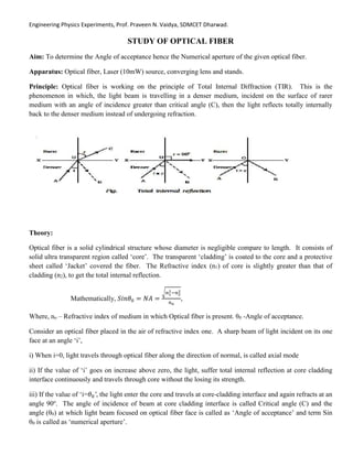
iv) If the value of i>𝜃0, then light beam entered into the core will completely refracts into the cladding.
For all the angle incidence, which equal to or less than critical angle light ray gives total internal reflection
through core, come out from the other face of optical fiber and falls on the screen placed on opposite side at
distance ‘l’ in circular shape of diameter ‘d’, now the critical angle θc is given by,
𝑡𝑎𝑛𝜃𝑐 =
𝑑/2
𝑙
𝑜𝑟 𝑡𝑎𝑛𝜃𝑐 =
𝑑
2𝑙
𝑜𝑟 𝐴𝑛𝑔𝑙𝑒 𝑜𝑓 𝑎𝑐𝑐𝑒𝑝𝑡𝑎𝑛𝑐𝑒, 𝜃𝑐 = 𝑡𝑎𝑛−1 𝑑
2𝑙
,
∴ 𝑁𝑢𝑚𝑒𝑟𝑖𝑐𝑎𝑙 𝐴𝑝𝑒𝑟𝑡𝑢𝑟𝑒, 𝑁. 𝐴 = 𝑆𝑖𝑛 [𝑡𝑎𝑛−1
𝑑
2𝑙
]
Procedure:
Set up the apparatus of optical fiber experiment as shown in the diagram.
The laser beam is to be converted into a sharp beam by the use of condensing lens.
The beam emerged of the lens is focused on the one face of optical fiber at right direction.
The screen with a white drawing paper fitted is kept opposite to other face of optical fiber, so that the beam
appeared on the screen.
The intensity of image of laser beam appeared on the screen is adjusted to be high.
Mark the circumference of image using pencil and hence measure its diameter (d). The length between
screen and optical fiber face also measured (l ).
Determine value of angle of acceptance, using formula 𝜃𝑐 = 𝑡𝑎𝑛−1 𝑑
2𝑙
and NA using formula
𝑁. 𝐴 = 𝑆𝑖𝑛 [𝑡𝑎𝑛−1
𝑑
2𝑙
]
Repeat the experiment for different values of ‘l’ and‘d’ and tabulate the readings.
Determine the average value of N.A. and note down the result.
θ0 O
C O θ0
l
d](https://image.slidesharecdn.com/opticalfiberexperiment-230511102124-736f9bfc/85/Optical-fiber-Experiment-docx-2-320.jpg)
![Engineering Physics Experiments, Prof. Praveen N. Vaidya, SDMCET Dharwad.
Diagram:
Formula used for calculation of Angle of acceptance.
𝜃0 = 𝑡𝑎𝑛−1
𝑑
2𝑙
Formula used for calculation of Numerical Aperture.
𝑁. 𝐴 = 𝑆𝑖𝑛 [𝑡𝑎𝑛−1
𝑑
2𝑙
]
Average value of Acceptance angle ____________o
,
Average value of Numerical aperture, N.A._______
Result: Acceptance angle of optical fiber ________________ o
.
Numerical aperture of the optical fiber ____________.
******
Trial
No.
Distance between
output end of the
optical fiber and
screen. ‘l’ cm
Diameter of the
image of the laser
beam on the screen
‘d’ cm
𝑑
2𝑙
Angle of
acceptance
𝜃0 = 𝑡𝑎𝑛−1
𝑑
2𝑙
Numerical
Aperture
𝑁. 𝐴 = 𝑆𝑖𝑛𝜃0
1
2
3
4
5
6
7
8](https://image.slidesharecdn.com/opticalfiberexperiment-230511102124-736f9bfc/85/Optical-fiber-Experiment-docx-3-320.jpg)

The document describes an engineering physics experiment focused on the study of optical fibers to determine their angle of acceptance and numerical aperture. It outlines the apparatus, principles, and procedures involved in measuring the critical angles and total internal reflection as light travels through the fiber. The experiment involves calculating the acceptance angle and numerical aperture based on the diameter of the laser image and the distance to the screen.


![Sectionanddevelopment(thedirectdata[1].com)](https://cdn.slidesharecdn.com/ss_thumbnails/sectionanddevelopmentthedirectdata1-170802182625-thumbnail.jpg?width=640&height=640&fit=bounds)


