Ekeeda is an online portal which creates and provides exclusive content for all branches engineering.To have more updates you can goto www.ekeeda.com..or you can contact on 8433429809...
The document discusses stress and strain under axial loading. It covers topics such as normal strain, stress-strain diagrams, Hooke's law, elastic and plastic behavior, fatigue, deformations under axial loading, static indeterminacy, thermal stresses, Poisson's ratio, generalized Hooke's law, shear strain, relations among elastic properties, composite materials, stress concentrations, and examples.
The document discusses stress and strain in engineering structures. It defines load, stress, strain and different types of each. Stress is the internal resisting force per unit area within a loaded component. Strain is the ratio of dimensional change to original dimension of a loaded body. Loads can be tensile, compressive or shear. Hooke's law states stress is proportional to strain within the elastic limit. The elastic modulus defines this proportionality. A tensile test measures the stress-strain curve, identifying elastic limit and other failure points. Multi-axial stress-strain relationships follow Poisson's ratio definitions.
This document provides an overview of topics related to simple stresses and strains, including:
- Types of stresses and strains such as tensile, compressive, direct stress, and direct strain.
- Hooke's law and how stress is proportional to strain below the material's yield point.
- Stress-strain diagrams and key points such as the elastic region, yield point, and fracture point.
- Definitions of terms like working stress, factor of safety, Poisson's ratio, and elastic moduli.
- Examples of problems calculating stresses, strains, extensions, and deformations of simple structural members under various loads.
This document provides information about the Solid Mechanics course ME 302 taught by Dr. Nirmal Baran Hui at NIT Durgapur in West Bengal, India. It lists four required textbooks for the course and provides a detailed syllabus covering topics like stress, strain, elasticity, bending, deflection, columns, torsion, pressure vessels, combined loadings, springs, and failure theories. The document also includes examples of lecture content on stress analysis, stresses on oblique planes, and material subjected to pure shear.
This document provides information about shear stresses and shear force in structures. It includes:
- Definitions of shear force and shear stress. Shear force is an unbalanced force parallel to a cross-section, and shear stress develops to resist the shear force.
- Explanations of horizontal and vertical shear stresses that develop in beams due to bending moments. Shear stress is highest at the neutral axis and reduces towards the top and bottom of the beam cross-section.
- Derivations of formulas for calculating shear stress across different beam cross-sections. Shear stress is directly proportional to the shear force and beam geometry.
- Examples of calculating maximum and average shear stresses for various cross-sections
This document provides an introduction and overview of mechanics of materials. It defines key terms like stress, strain, normal stress, shear stress, factor of safety, and allowable stress. It also gives examples of calculating stresses in structural members subjected to various loads. The document is an introductory reading for a mechanics of materials course that will analyze the relationship between external forces and internal stresses and strains in structural elements.
The document discusses different types of strain energy stored in materials when subjected to loads. It defines strain energy as the work done or energy stored in a body during elastic deformation. The types of strain energy discussed include: elastic strain energy, strain energy due to gradual, sudden, impact, shock and shear loading. Formulas are provided to calculate strain energy due to these different loadings. Examples of calculating strain energy in axially loaded bars and beams subjected to bending and torsional loads are also presented.
The document discusses Deepak's academic and professional background, including an MBA from IE Business School in Spain and experience founding perfectbazaar.com. It also provides an overview of the topics to be covered in the Strength of Materials course, such as stresses, strains, Hooke's law, and analysis of bars with varying cross-sections. The grading policy and syllabus are outlined which divide the course into 5 units covering various strength of materials concepts.
This document outlines an introduction to strength of materials course taught by Dr. Dawood S. Atrushi. The course covers topics such as simple stress and strain, shear force and bending moment diagrams, stresses in beams, and torsion. It discusses how strength of materials relates to other areas of mechanics and engineering. The course aims to help students understand how different forces affect structural components and materials, and analyze stresses and deformations. SI units and concepts like stress, internal forces, and free-body diagrams are also introduced.
Stresses and its components - Theory of Elasticity and PlasticityAshishVivekSukh
Stress at any section is internal resistance offered by metal against the deformation caused by applied load.
It is Internal resistance pre-unit area.
When a metal is subjected to a load, it is deformed, no matter how strong the metal.
If the load is small, the distortion will probably disappear when the load is removed.
If the distortion disappears and the metal returns to its original dimensions upon removal of the load, the strain is called elastic strain.
If the distortion disappears and the metal remains distorted, the strain type is called plastic strain
This document provides an overview of simple stress and strain concepts including:
- Stress is defined as the internal resisting force per unit area acting on a material. It can be expressed as the limit of the distributed force over an infinitesimal area as the area approaches zero.
- Normal stress is the intensity of force acting normally to a section, while shear stress is the intensity of force acting tangentially.
- For long, slender beams that experience uniform tensile or compressive stress, the average normal stress can be calculated as the total force divided by the cross-sectional area.
This document discusses bending stresses in beams. It defines simple or pure bending as when a beam experiences zero shear force and constant bending moment over a length. For simple bending, the stress distribution can be calculated using beam theory. The key points are:
- Bending stresses are introduced due to bending moments and are highest at the extreme fibers furthest from the neutral axis.
- The neutral axis experiences no bending stress and its location is defined by the centroidal axis of the beam cross-section.
- Bending stress is directly proportional to the distance from the neutral axis. The stress distribution follows σ = My/I, where M is the bending moment, y is the distance from neutral axis, and I is
The document discusses beams, which are horizontal structural members that support applied loads. It defines applied and reactive forces, and describes different types of supports including roller, hinge, and fixed supports. It then defines and describes different types of beams, including cantilever, simply supported, overhanging, fixed, and continuous beams. It also discusses types of loads, including concentrated and distributed loads, and how beams experience both bending and shear forces from loads.
ppt about simple stress and strains. use full for B.E. in 3 semester. all content of chapter are covered in this ppt. i hope this is useful fore some peoples.if you like then plz click lick.
The document discusses key concepts related to elastic, homogeneous, and isotropic materials including: limits of proportionality and elasticity, yield limit, ultimate strength, strain hardening, proof stress, and the stress-strain relationships of ductile and brittle materials. It provides definitions and examples for each term and describes the stress-strain graphs for ductile materials like mild steel and brittle materials.
1. When a force is applied to a body, it causes the body to deform or change shape. This deformation is called strain. Direct stress is calculated as the applied force divided by the cross-sectional area.
2. Materials deform both elastically and plastically when stressed. Elastic deformation is reversible but plastic deformation causes a permanent change in shape. Hooke's law describes the linear elastic behavior of many materials, where stress is directly proportional to strain up to the elastic limit.
3. Thermal expansion and contraction can induce stress in materials as temperature changes unless deformation is unconstrained. The total strain is the sum of strain due to stress and strain due to temperature changes.
1. The document discusses various types of mechanical loading and stresses including tensile, compressive, shear, bending, and torsional stresses.
2. It describes different types of strains and properties of materials like elasticity, plasticity, ductility. Hooke's law and relationships between stress and strain are explained.
3. Methods for analyzing stresses in machine components subjected to combinations of loads are presented, including principal stresses, Mohr's circle, and thermal stresses. Bending stresses and shear stresses are analyzed for beams under different support conditions.
Bending Stresses are important in the design of beams from strength point of view. The present source gives an idea on theory and problems in bending stresses.
This document summarizes key concepts related to structural analysis including:
1) The effects of axial and eccentric loading on columns including direct stress, bending stress, and maximum/minimum stresses.
2) Maximum and minimum pressures at the base of dams and retaining walls including calculations of total water/earth pressure, eccentricity, and stability conditions.
3) Forces and stresses on chimneys and walls due to wind pressure including calculations of direct stress from self-weight, wind force, induced bending moment, and maximum/minimum stresses.
This document provides an overview of stress, strain, and modulus of elasticity concepts in mechanical engineering. It defines stress as force per unit area, strain as the deformation per original length. Hooke's law states deformation is directly proportional to force. The modulus of elasticity E is the constant of proportionality between stress and strain. A stress-strain diagram is presented showing the elastic region, yield point, plastic region, strain hardening, and necking behavior. Shear stress and modulus of rigidity G are also defined. Design considerations like factor of safety are discussed for selecting allowable loads below ultimate strengths.
What is Bending Moment?
What are its sign conventions?
What is BMD?
What is the difference between moment and bending moment?
Find out answers for these questions and many more in this presentation.
This document discusses beam theory and provides equations for calculating the deflection and slope of beams under different loading conditions. It defines key terms like bending moment, radius of curvature, flexural stiffness, and provides equations relating these terms. Specifically, it gives the deflection and slope equations for a cantilever beam with a point load, cantilever with uniform load, simply supported beam with central point load, and simply supported beam with uniform load.
The document provides information about bending stresses and shear stresses in beams. It includes definitions of key terms like bending moment, shear force, radius of gyration, moment of inertia. It describes the assumptions in simple bending theory and concepts of neutral layer and neutral axis. Flexural formulas for pure bending and stress distribution diagrams are presented. Formulas for moment of inertia of various cross sections and moment of resistance are provided. Two example problems are included, one calculating moment of inertia for a rectangular lamina and another finding maximum stress induced in a beam with a non-uniform cross section.
1. Strain energy is the energy stored in a body when it is strained within the elastic limit due to an applied load. The formula for strain energy is U = σ2/2E x V, where U is strain energy, σ is stress, E is modulus of elasticity, and V is volume.
2. Resilience is the total strain energy stored in a body within the elastic limit. Proof resilience is the maximum strain energy that can be stored at the elastic limit. Modulus of resilience is the maximum strain energy that can be stored per unit volume at the elastic limit.
3. An impact or shock load is a sudden load applied to a body, such as a load falling from
This document provides information about the Strength of Materials CIE 102 course for first year B.E. degree students. It includes a list of 10 topics that will be covered in the course, such as simple stress and strain, shearing force and bending moment, and stability of columns. It also lists several reference books for the course and provides an overview of concepts that will be discussed in the first chapter, including stress, strain, stress-strain diagrams, and ductile vs brittle materials.
1) Bending moment is a measure of the bending effect on a beam due to applied forces and is measured in units of Newton-meters or foot-pounds force.
2) The bending moment equation is the algebraic sum of the moments about a section of the beam from all forces acting on one side.
3) Positive bending moments cause tension in the bottom fibers and compression in the top fibers (sagging) while negative moments cause the opposite (hogging).
Some basic defintions of the topics used in Strength of Materials subject. Pictorial presentation is more than details. Many examples are provided as well.
Strength of Materials Lecture - 2
Elastic stress and strain of materials (stress-strain diagram)
Mehran University of Engineering and Technology.
Department of Mechanical Engineering.
This document provides an overview of strength of materials and introduces key concepts. It discusses stress and strain, ductile and brittle materials, and stress-strain diagrams. Stress is defined as the internal resisting force per unit area acting on a material. Strain is the ratio of change in dimension to the original dimension when a body is subjected to external force. Ductile materials show deformation under stress, while brittle materials do not. The stress-strain diagram shows the relationship between stress and strain for ductile and brittle materials.
This document provides an overview of the syllabus and objectives for the course CE8395 Strength of materials for Mechanical Engineers. It outlines the 5 units that will be covered: 1) Stress, Strain and Deformation of Solids, 2) Transverse Loading on Beams and Stresses in Beam, 3) Torsion, 4) Deflection of Beams, and 5) Thin Cylinders, Spheres and Thick Cylinders. Key concepts that will be studied include stresses, strains, principal stresses, shear force and bending moment in beams, torsion, deflections, and stresses in thin shells and cylinders. The document also provides two mark questions and answers related to stress, strain, elastic properties
The document discusses stress and strain in materials. It introduces the key concepts of normal stress, shear stress, bearing stress, and thermal stress. Normal stress acts perpendicular to a cross-section, shear stress acts tangentially, and bearing stress occurs at contact points. The relationships between stress, strain, elastic modulus, and Poisson's ratio are explained. Methods for calculating stress and strain in axial loading, torsion, bending and combined loading are presented through examples. The stress-strain diagram is discussed to show material properties like yield strength and ductility.
This document discusses the mechanical properties of solids, including elasticity, plasticity, stress, strain, elastic limit, Hooke's law, modulus of elasticity, and stress-strain curves. It defines key terms and concepts related to how solids deform under force. Examples are given of how understanding mechanical properties informs applications like designing ropes for cranes and bridges to withstand loads within safe elastic limits. The maximum possible height of mountains is also calculated based on the shear modulus of typical rock.
Chapter-1 Concept of Stress and Strain.pdfBereketAdugna
The document discusses concepts of stress and strain in materials. It defines stress as an internal force per unit area within a material. Stress can be normal (perpendicular to the surface) or shear (parallel to the surface). Normal stress can be tensile or compressive. Strain is a measure of deformation in response to stress. Hooke's law states that stress is proportional to strain in the elastic region. Poisson's ratio describes the contraction that occurs perpendicular to an applied tensile load. Stress-strain diagrams are used to analyze a material's behavior under different loads. The document also discusses volumetric strain, shear stress and strain, bearing stress, and provides examples of stress and strain calculations.
Diploma sem 2 applied science physics-unit 2-chap-1 elasticityRai University
Elastic and plastic deformation are described. Elastic deformation is reversible and no permanent change occurs. Plastic deformation results in a permanent change in shape as interatomic bonds are broken. Stress is defined as force over area, and strain as the ratio of deformation to original length. Hooke's law states that stress is proportional to strain within the elastic limit. The elastic moduli - Young's modulus, shear modulus, and bulk modulus - are defined relating stress and strain. Poisson's ratio describes the lateral contraction that occurs during stretching. Examples show calculations of stress, strain, and dimensions based on given loads and properties.
mechanics of structure(CE3G)- simple stress & strain.pptDrAnkitaUpadhya
This document covers topics related to stress and strain including:
- Definitions of stress as force per unit area and strain as deformation per original length. Stress is proportional to strain below the proportional limit according to Hooke's law.
- The stress-strain diagram shows elastic behavior, yield point, plastic deformation, strain hardening, necking and fracture.
- Shear stress is defined as force per unit area applied sideways. Shear strain is the ratio of deformation to original height. Shear modulus relates shear stress and strain.
- Materials have ultimate tensile, compressive and shear stresses at which they fail. Design allows only a fraction of these stresses for safety.
1. The document defines key terms related to loads, stresses, strains, and elastic behavior of materials. It describes different types of loads, stresses, strains and their relationships based on Hooke's law.
2. Formulas are provided for calculating tensile stress, compressive stress, shear stress, elastic modulus, and deformation of tapered and composite bars.
3. The principles of superposition and self-weight induced stresses in cantilever beams are also summarized.
This document provides an overview of stresses in beams due to bending. It defines key terms like beam, bending moment, neutral axis, and radius of curvature. It then derives the bending formula that relates stress, bending moment, moment of inertia, and distance from the neutral axis. Several examples are worked through to demonstrate calculating stress in standard beam cross sections given bending moment values. The document concludes with self-assessment exercises for the reader.
I. The course aims to enable students to relate material properties to behavior under loads, analyze loaded structural members, and evaluate stresses, strains, and deflections.
II. The course structure covers stresses and strains, shear force and bending moment diagrams, flexural and shear stresses in beams, torsion of circular shafts, and columns and struts.
III. Teaching methods include lectures involving tutorial solutions, coursework assignments, and daily assessment. The course examines topics like stress-strain relationships, thermal and volumetric strains, Hooke's law, modulus of elasticity, yield stresses, and factors of safety.
Machine elements are basic mechanical components that are combined to form machines. They experience various stresses from forces like loads, temperature changes, and vibrations. Stresses produce strains in the elements. The relationship between stress and strain is linear within the elastic limit according to Hooke's law. Different types of stresses like tensile, compressive, shear, and bearing are discussed along with the corresponding strains. Material properties important for design like modulus of elasticity, Poisson's ratio, and stress-strain diagrams are also introduced. Factors to consider for selecting appropriate materials and factors of safety for machine elements are outlined.
Mohamad Redhwan Abd Aziz is a lecturer at the DEAN CENTER OF HND STUDIES who teaches the subject of Solid Mechanics (BME 2023). The 3 credit hour course involves 2 hours of lectures and 2 hours of labs/tutorials each week. Student assessment includes quizzes, assignments, tests, lab reports, and a final exam. The course objectives are to understand stress, strain, and forces in solid bodies through various principles and experiments. Topic areas covered include stress and strain, elasticity, shear, torsion, bending, deflection, and more. References for the course are provided.
Strengthofmaterialsbyskmondal 130102103545-phpapp02Priyabrata Behera
This document contains a table of contents for a book on strength of materials with 16 chapters covering topics like stress and strain, bending, torsion, columns, and failure theories. It also contains introductory material on stress, strain, Hooke's law, true stress and strain, volumetric strain, Young's modulus, shear modulus, and bulk modulus. Key definitions provided include normal stress, shear stress, tensile strain, compressive strain, engineering stress and strain, true stress and strain, Hooke's law, and the relationships between elastic constants.
The document discusses various topics relating to material properties and crystal structure:
- Crystal structure determines material properties and is the arrangement of atoms in the material. The smallest repeating unit that can generate the crystal structure is called the unit cell.
- Metallic crystals have densely packed structures due to small atomic radii and non-directional metallic bonding. Common unit cell structures are simple cubic, body centered cubic, and face centered cubic.
- Mechanical properties like stress, strain, elastic moduli, ductility, and toughness are influenced by the crystal structure and affect how the material responds to forces. The stress-strain curve provides information on a material's elastic and plastic deformation.
- Other topics covered
1) Materials deform when stressed, returning to original shape within the elastic limit. Beyond this, deformation is permanent.
2) Hooke's law describes the linear relationship between stress and strain within the elastic limit. The slope is Young's modulus, a measure of stiffness.
3) Poisson's ratio defines the lateral contraction that occurs when a material is stretched. Most materials contract laterally to some degree.
- Stress is the internal resisting force per unit area caused by external forces. It is measured in units of pressure like Pa or MPa. Strain is the deformation per original length and is dimensionless.
- Hooke's law states that deformation is directly proportional to applied force. The constant of proportionality is the modulus of elasticity E. A graph of stress vs strain results in a straight line with slope E.
- Materials have a maximum stress level before breaking called the ultimate tensile stress. Shear stress is caused by sideways forces and measured as force per unit area. Shear strain is the ratio of deformation to original height for small angles. The modulus of rigidity G defines the relationship between shear
Introduction to Mechanical Properties of Fluids
Fluids, encompassing both liquids and gases, exhibit intriguing behaviours that can be understood through the study of their mechanical properties. Class 11 introduces students to the fundamental concepts that govern how fluids behave under various conditions. From the density and pressure of fluids at rest to their dynamic characteristics during flow, this chapter delves into the essential principles shaping the behaviour of fluids. Topics such as Pascal's Law, hydrostatic pressure, Bernoulli's Principle, viscosity, and surface tension form the core of understanding the intricate world of fluid mechanics. As we explore these mechanical properties, we unlock insights into the forces that govern fluid motion, buoyancy, and the dynamic equilibrium within these fascinating substances. This foundation lays the groundwork for comprehending more complex fluid dynamics in higher studies and real-world applications.
For more information, visit. www.vavaclasses.com
Theoretical concepts, and practical examples, students explore how materials respond to external forces, how they deform under stress, and how they ultimately fail. They learn about concepts such as Hooke's Law, which describes the linear relationship between stress and strain within the elastic limit of a material, and they delve into the factors that influence the mechanical behavior of solids, including material microstructure, temperature, and rate of loading.
For more information, visit-www.vavaclasses.com
Fluid mechanics is a crucial branch of physics that deals with the behavior of fluids, both liquids and gases, under various conditions. Understanding the mechanical properties of fluids is essential for grasping the fundamentals of fluid mechanics. In this set of study notes, we delve into the key concepts related to mechanical properties of fluids targeted specifically for Class 11 students.
For more information, visit- www.vavaclasses.com
In this section the concept of stress will be introduced, and this will be applied to components that are in a state of tension, compression, and shear. Strain measurement methods will also be briefly discussed.
A review on techniques and modelling methodologies used for checking electrom...nooriasukmaningtyas
The proper function of the integrated circuit (IC) in an inhibiting electromagnetic environment has always been a serious concern throughout the decades of revolution in the world of electronics, from disjunct devices to today’s integrated circuit technology, where billions of transistors are combined on a single chip. The automotive industry and smart vehicles in particular, are confronting design issues such as being prone to electromagnetic interference (EMI). Electronic control devices calculate incorrect outputs because of EMI and sensors give misleading values which can prove fatal in case of automotives. In this paper, the authors have non exhaustively tried to review research work concerned with the investigation of EMI in ICs and prediction of this EMI using various modelling methodologies and measurement setups.
Advanced control scheme of doubly fed induction generator for wind turbine us...IJECEIAES
This paper describes a speed control device for generating electrical energy on an electricity network based on the doubly fed induction generator (DFIG) used for wind power conversion systems. At first, a double-fed induction generator model was constructed. A control law is formulated to govern the flow of energy between the stator of a DFIG and the energy network using three types of controllers: proportional integral (PI), sliding mode controller (SMC) and second order sliding mode controller (SOSMC). Their different results in terms of power reference tracking, reaction to unexpected speed fluctuations, sensitivity to perturbations, and resilience against machine parameter alterations are compared. MATLAB/Simulink was used to conduct the simulations for the preceding study. Multiple simulations have shown very satisfying results, and the investigations demonstrate the efficacy and power-enhancing capabilities of the suggested control system.
Optimizing Gradle Builds - Gradle DPE Tour Berlin 2024Sinan KOZAK
Sinan from the Delivery Hero mobile infrastructure engineering team shares a deep dive into performance acceleration with Gradle build cache optimizations. Sinan shares their journey into solving complex build-cache problems that affect Gradle builds. By understanding the challenges and solutions found in our journey, we aim to demonstrate the possibilities for faster builds. The case study reveals how overlapping outputs and cache misconfigurations led to significant increases in build times, especially as the project scaled up with numerous modules using Paparazzi tests. The journey from diagnosing to defeating cache issues offers invaluable lessons on maintaining cache integrity without sacrificing functionality.
Embedded machine learning-based road conditions and driving behavior monitoringIJECEIAES
Car accident rates have increased in recent years, resulting in losses in human lives, properties, and other financial costs. An embedded machine learning-based system is developed to address this critical issue. The system can monitor road conditions, detect driving patterns, and identify aggressive driving behaviors. The system is based on neural networks trained on a comprehensive dataset of driving events, driving styles, and road conditions. The system effectively detects potential risks and helps mitigate the frequency and impact of accidents. The primary goal is to ensure the safety of drivers and vehicles. Collecting data involved gathering information on three key road events: normal street and normal drive, speed bumps, circular yellow speed bumps, and three aggressive driving actions: sudden start, sudden stop, and sudden entry. The gathered data is processed and analyzed using a machine learning system designed for limited power and memory devices. The developed system resulted in 91.9% accuracy, 93.6% precision, and 92% recall. The achieved inference time on an Arduino Nano 33 BLE Sense with a 32-bit CPU running at 64 MHz is 34 ms and requires 2.6 kB peak RAM and 139.9 kB program flash memory, making it suitable for resource-constrained embedded systems.
Literature Review Basics and Understanding Reference Management.pptxDr Ramhari Poudyal
Three-day training on academic research focuses on analytical tools at United Technical College, supported by the University Grant Commission, Nepal. 24-26 May 2024
Using recycled concrete aggregates (RCA) for pavements is crucial to achieving sustainability. Implementing RCA for new pavement can minimize carbon footprint, conserve natural resources, reduce harmful emissions, and lower life cycle costs. Compared to natural aggregate (NA), RCA pavement has fewer comprehensive studies and sustainability assessments.
Harnessing WebAssembly for Real-time Stateless Streaming PipelinesChristina Lin
Traditionally, dealing with real-time data pipelines has involved significant overhead, even for straightforward tasks like data transformation or masking. However, in this talk, we’ll venture into the dynamic realm of WebAssembly (WASM) and discover how it can revolutionize the creation of stateless streaming pipelines within a Kafka (Redpanda) broker. These pipelines are adept at managing low-latency, high-data-volume scenarios.
Understanding Inductive Bias in Machine LearningSUTEJAS
This presentation explores the concept of inductive bias in machine learning. It explains how algorithms come with built-in assumptions and preferences that guide the learning process. You'll learn about the different types of inductive bias and how they can impact the performance and generalizability of machine learning models.
The presentation also covers the positive and negative aspects of inductive bias, along with strategies for mitigating potential drawbacks. We'll explore examples of how bias manifests in algorithms like neural networks and decision trees.
By understanding inductive bias, you can gain valuable insights into how machine learning models work and make informed decisions when building and deploying them.
A SYSTEMATIC RISK ASSESSMENT APPROACH FOR SECURING THE SMART IRRIGATION SYSTEMSIJNSA Journal
The smart irrigation system represents an innovative approach to optimize water usage in agricultural and landscaping practices. The integration of cutting-edge technologies, including sensors, actuators, and data analysis, empowers this system to provide accurate monitoring and control of irrigation processes by leveraging real-time environmental conditions. The main objective of a smart irrigation system is to optimize water efficiency, minimize expenses, and foster the adoption of sustainable water management methods. This paper conducts a systematic risk assessment by exploring the key components/assets and their functionalities in the smart irrigation system. The crucial role of sensors in gathering data on soil moisture, weather patterns, and plant well-being is emphasized in this system. These sensors enable intelligent decision-making in irrigation scheduling and water distribution, leading to enhanced water efficiency and sustainable water management practices. Actuators enable automated control of irrigation devices, ensuring precise and targeted water delivery to plants. Additionally, the paper addresses the potential threat and vulnerabilities associated with smart irrigation systems. It discusses limitations of the system, such as power constraints and computational capabilities, and calculates the potential security risks. The paper suggests possible risk treatment methods for effective secure system operation. In conclusion, the paper emphasizes the significant benefits of implementing smart irrigation systems, including improved water conservation, increased crop yield, and reduced environmental impact. Additionally, based on the security analysis conducted, the paper recommends the implementation of countermeasures and security approaches to address vulnerabilities and ensure the integrity and reliability of the system. By incorporating these measures, smart irrigation technology can revolutionize water management practices in agriculture, promoting sustainability, resource efficiency, and safeguarding against potential security threats.
Presentation of IEEE Slovenia CIS (Computational Intelligence Society) Chapte...University of Maribor
Slides from talk presenting:
Aleš Zamuda: Presentation of IEEE Slovenia CIS (Computational Intelligence Society) Chapter and Networking.
Presentation at IcETRAN 2024 session:
"Inter-Society Networking Panel GRSS/MTT-S/CIS
Panel Session: Promoting Connection and Cooperation"
IEEE Slovenia GRSS
IEEE Serbia and Montenegro MTT-S
IEEE Slovenia CIS
11TH INTERNATIONAL CONFERENCE ON ELECTRICAL, ELECTRONIC AND COMPUTING ENGINEERING
3-6 June 2024, Niš, Serbia
IEEE Aerospace and Electronic Systems Society as a Graduate Student Member
1. simple stress and strains
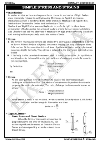
1. EKEEDA CONTACT: 9029006464
www.ekeeda.com simple stress & strains1
SIMPLE STRESS AND STRAINS
Introduction:-
In earlier studies we have undergone a basic course in mechanics of Rigid Bodies,
more commonly referred to as Engineering Mechanics or Applied Mechanics.
Mechanics as such is subdivided into three branches; Mechanics of Rigid bodies,
Mechanics of Deformable Bodies and Mechanics of fluids.
Mechanics of Rigid Bodies assumed bodies to be perfectly rigid i.e. there is no
deformation of bodies under the action of loads to which they are subjected statics
and Dynamics are the two branches of Mechanics Of rigid Bodies involving stationary
and moving bodies respectively under the action of loads.
Stress:-
i. The force of resistances per unit are offered by a body against deformation is known
as Stress. When a body is subjected to external loading the body undergoes some
deformation. At the same time internal force of resistance is due to the cohesion of
molecules inside the body. Thus stress is induced in the body upon external action
of load
ii. If the body is able to resist the external load , it is said to be stable , in equilibrium
and therefore for this condition the internal force of resistance should be equal to
the external load.
By Definition
Or
Strain:-
As the body produce force of resistance to counter the external loading it
undergoes some deformation .The extent of deformation depend on the material
property like molecular cohesion .The ratio of change in dimension is known as
strain.
Changeindimension
Strain =
Originaldimension
Since Strain is ratio, it has no units. We shall denote strain by letter e. If L is the
original dimension and is change in dimension and then
δL
Strain = e =
L
Types of Stress:-
1) Direct Stress and Direct Strain:-
When the force of resistance acts normal or
perpendicular to the area on which it acts, the
stress so produced is termed as Direct or Normal
Stress and corresponding strain is referred to as
Direct Strain.
forceof resistance
Stress =
Cross-sectionalarea
P
Stress =
A
2. EKEEDA CONTACT: 9029006464
www.ekeeda.com simple stress & strains2
forceof resistance toc/sarea
c/sarea on which forceof resistanceacts
Direct Stress
R
f
A
P
f
A
We shall denote direct stress by letter 'f'. Direct stress could be of tensile nature of
compressive nature.
2) Tensile stress:-
When the force of resistance acts away from the cross sectional area, the direct
stress is of tensile nature. Tensile stresses tend to cause an increase in the original
dimension.
3) Compressive Stress:-
When the force of resistance acts towards the cross sectional area, the direct stress is of
compressive in nature .Compressive stresses tend to cause a decrease in the original
dimension.
Stress–Strain curve for Ductile Materials:-
1) Proportional Limit:-
It is the point (A) upto which stress is proportional
to strain and the material obeys Hooke’s Law.
2) Elastic Limit:-
It is a point (B) very close to A upto which the
material is said to be elastic.
3) Yield Point:-
It is a region from point C upto point D where the
curves is nearly flat or horizontal indicating no
increase in stress but appreciable increase in
strain.
4) Ultimate stress:-
It is the point E on the graph and is the maximum stress which the material can
with stand before it finally fails.
5) Breaking Point:-
3. EKEEDA CONTACT: 9029006464
www.ekeeda.com simple stress & strains3
Any ductile material does not fail at the ultimate stress point but before failure the
necking of the specimen takes place which leads to failure.
Stress-Strain Curve for Brittle materials:-
i. Brittle materials undergo very little deformation on tensile loading and fail at low
tensile loads. Brittle materials absorb little energy on impact. Glass, cast-iron,
concrete etc. are examples of brittle materials.
ii. The stress-strain curve for a brittle material shows low proportional limit and also a
low ultimate stress value. The yield point (A) is not very well defined and
approximations are used to locate it. The Ultimate stress point and Breaking point
(B) are the same.
Hooke’s Law:-
Stress is proportional to strain and the material is fully elastic in this region. This is
known as Hooke`s law.
f e
or f = E.e
E =
f
e
Relation for Change in Length of a Material of a Member under Direct Stress:-
4. EKEEDA CONTACT: 9029006464
www.ekeeda.com simple stress & strains4
P
Wehave directstressf =
A
δL
also Strain e =
L
f
Also Modulus of ElectricityE =
e
Combining theabove equation weget
PL
Change in Lenght δL =
AE
The ratio of Ultimate stress to safe stress is known as the Factor of Safety. It works
as a protective shield against failure of material under stress.
Ultimatestress
Factory of Safety =
Safe stress
Deformation of Uniformly Tapering Circular Section Bar:-
Consider a tapering rod with diameter D at one end which tapers uniformly to
diameter d at the other end over a length L. Let the rod be subjected to an axial tensile
load of P. Consider an element of length dx located at distance x from the smaller end.
The element would also be under the axial pull P.
Length of element eL dx
Diameter of the element e
D d
d d x
L
c/s area of the element
2
2
4 4
e e
D d
A d d x
L
Change in length of element e
e
P L
Le
A E
2
4
p dx
D d
d x E
L
Total change in length of the rod
2
0
4
L
Pdx
L
D d
E d x
L
5. EKEEDA CONTACT: 9029006464
www.ekeeda.com simple stress & strains5
0
4 1
L
P L
L
D dE D d
d x
L
4 1 1
( )
PL
L
E D d D d
4PL
L
EDd
……………… 1.7 Deformation of circular tapering rod
Deformation of Uniformly Tapering Rectangular Section Bar:-
Consider a tapering bar of uniform thickness t with side a on one end which tapers
uniformly to side b at the other end over a length L. Let the rod be subjected to an axial
tensile load P. Consider an element of length dx located at distance x from the smaller
end. The element would also be under the axial pull P.
Length of element eL dx
Tapering side of the element =
a b
b x
L
c/s area of the element e
a b
A b x t
L
Change in length of element e
e
P L
Le
A E
P dx
a b
b x t E
L
Total change in length of the bar
0
L
Pdx
L
a b
tE b x
L
log
L
e
o
P L a b
L b x
tE a b L
6. EKEEDA CONTACT: 9029006464
www.ekeeda.com simple stress & strains6
log
( )
e
PL a
L
tE a b b
……….. Deformation of rectangular tapering bar
Deformation due to Self Weight
Member when vertically suspended from one end, may
undergo elongation under its own weight. This deformation is
usually very small in magnitude as compared to other deformation.
However if the length of the suspended member is large, the
elongation due to self weight becomes appreciable.
Uniform Rod Under Self Weight:-
Let us derive a relation for elongation of a uniform rod and
relation for direct stress when supported in a vertical
position by suspending if from the top-most point of the
rod.
Figure shows a rod of uniform c/s area A, modulus of
elasticity E and length L.
Let be the unit weight of the material of the rod.
Consider a section x-x at distance y from the bottom.
The weight of the portion below the section xx ( )A y
Stress at section x –x =
.
/
P wt of portionbelow x x
A c s area
. ..... stress at a distance y from the bottom
A y
f
A
f y
Consider an element of length ‘dy’ being elongated due to force P at
section x-x
Change in length of the element =
( )PL A y dy
AE AE
. y dy
E
Total change in length of member =
0
.
L
y dy
E
2
2
L
L
E
….elongation of uniform rod under self weight
7. EKEEDA CONTACT: 9029006464
www.ekeeda.com simple stress & strains7
Analysis of Members Made of Composite Materials:-
Member made up of more than one material are referred to as composite members.
Members are intentionally made of composite materials to increase mainly their load
carrying capacity and also other parameters effecting strength, stiffness and stability.
For solving problems on composite materials we develop two basic relations, these
are
(1) Load Shearing Relation :
This relation relates the individual loads carried by different materials to the
total load carried by the composite member.
(2) Strain Relation :
This relation relates the deformation of different materials of the composite
section.
Shear Stress:-
When the load acts tangential to the cross-sectional area it tends to shear or cut the
member. When the blades of the scissor of the scissor cut a paper the force of the
blades act tangential to the cross-section of the
paper and the effect is shearing of the paper.
Shear stress is defined as the shear resistance per
unit shear area. We shall denote shear stress by
Greek letter .
Shear Resistance
Share Stress =
Shear Area
R
=
b×d
Shear Force
ShearStress τ =
Shear Area
S.I. Unit of Shear Stress is N/m2
Single Shear and Double Shear:-
1) Single Shear:-
When the shearing force causes the resistance shear to act at only one plane the
shear is referred to as single shear.
Refer to which shows two plates connected by a rivet. If force P acts in the two
plates as shown. The rivet is subjected to single shear. The shear resistance is
seen acting at one plane.
2) Double Shear:-
When the shearing force causes the resistance shear to act at two planes the shear
is referred to as double shear.
8. EKEEDA CONTACT: 9029006464
www.ekeeda.com simple stress & strains8
Refer to Fig. which shows a member connected by a bolt to a change. If force P acts
on the member as shown. The bolt is subjected to double shear. The shearing
resistance acts at two planes as seen in the figure
3) Temperature Stress:-
Materials tend to naturally expand or contract due to rise or fall in temperature.
This expansion or contraction which takes place is known as free expansion or free
contraction of the materials and is proportional to
A. the change in temperature ‘T’
B. coefficient of linear thermal expansion of the material ‘α’ and
C. the original length of the member ‘L’
Free expansion or contraction T L
No temperature stresses are generated
in the member if the free expansion or
contraction is allowed.
Whenever the free expansion or
contraction of a material is prevented,
temperature stresses which are
compressive or tensile in nature are
developed.
Temperature strain and temperature
stresses are calculated using the following
relation
PrExpansion or Contraction evented
Temperature Strain
Original Length
Temperature Stress E Temperature Strain
Temperature stresses become important in situations where the temperature is
likely to change by large amount. For example, in a railway track.
4) Lateral Strain:-
9. EKEEDA CONTACT: 9029006464
www.ekeeda.com simple stress & strains9
When direct axial load is applied on the member the length of the member changes,
but this is accompanied by changes in lateral dimensions too. Lateral dimensions
are the dimensions at right angles to the axis of the member.
Fig. Shows a bar of length L, breadth b and depth d subjected to axial tensile load.
The length L increases by ,L but the lateral dimensions b and d decrease by
b and d respectively. Fig shows axial compressive load and here the length
decreases the lateral dimensions increase.
We have seen Strain
L
L
Now we will be more specific, and call this strain which is along the direction of the
force as Longitudinal Strain.
δL
Longitudinal Strain, longitudinal=
L
The Lateral Strain is the ratio of change in lateral dimension to the original lateral
dimension.
Changein LaterealDimension
Letereal Strain =
OrigionalLeteraldimension
Lateral Strain, lateral =
b d
b d
In case of bars with circular cross-section
latereal= Where D is the rod`s diametere D
D
Lateral strains are always opposite in nature to the longitudinal strain. For tensile
stress, the length increases whereas the lateral dimension increases whereas the
length decreases. Lateral strains are smaller in magnitude as compared to
longitudinal strain.
5) Poisson’s Ratio:-
For a given material the ratio of lateral strain to the longitudinal strain is a
constant within certain limits. This ratio is termed as Poisson’s ratio.
1
It is denoted as
m
1 LeteralStrain
Poisson'sRatio =
m LongituinalStrain
1 elateral
=
m elogitudinal
Most of the materials used in engineering applications have Poisson`s Ratio
between 0.25 and 0.35.
10. EKEEDA CONTACT: 9029006464
www.ekeeda.com simple stress & strains10
6) Volumetric Strain:-
Volumetric strain is defined as the ratio change in volume to the original volume.
Volumetric strain is denoted as Ve
V
changein Volume
Volume Strain e =
OriginalVolume
Volumetric Strain for Uni-Axial Loading
A body subjected to axial force in one direction and hence the stress
developing along one single direction, is said to be under Uni-Axial loading.
Figure shows a bar subjected to stress in the x direction.
Volumetric Strain ve under Uni-Axial Loading,
log 2v itudinal laterale e e …………………
or
1
2v
f f
e
E M E
2
1v
f
e
E M
……………….. Volumetric Strain in terms of stress
Note: In equation if the load is tensile longitudinale is positive and laterale is negative. For
compressive load, longitudinale is negative and laterale is positive. In equation stress f
is positive if the load is tensile and negative if load is compressive.
Volumetric Strain for Tri-Axial Loading
A body subjected to axial forces in all three directions and hence the
stresses developing along all the three directions, is said to be under Tri-Axial
loading.
Volumetric Strain ve under Tri-Axial Loading
11. EKEEDA CONTACT: 9029006464
www.ekeeda.com simple stress & strains11
v x y ze e e e
Here ,xe ye and ze are the strains in the ,x y and z directions respectively.
yx z
x
ff f
e
E mE mE
y x z
y
f f f
e
E mE mE
yxz
z
fff
e
E mE mE
2x yf f f f …….Volumetric Strain in terms of stress
We shall use +ve values of stress if they are tensile and -ve values of stress if they
are compressive.
7) Bulk Modulus:-
The ratio of direct stress to the volumetric strain produced in the material within
certain limits is a constant and is referred to as Bulk Modulus. It is a material
properly like E and G.
Bulk Modulus is denoted by letter K and its S.I. unit is 2
N / m .
Hence Bulk Modulus
v
f
K
e
Relation between E and G
Consider a solid cube subjected to shear force F at the top face. This produces
shear stress on faces AB and CD and complementary shear stress on face BC and AD.
The distortion due to shear stress is shown by dotted lines. The diagonal AC also distorts
to AC.
Now, Shear strain
'CC
BC
Modulus of Rigidity
Shear Stress
G
Shear Strain
Shear Stress
Shear strain
G
'CC
BC G
…………… (1)
From C drop a on the distorted diagonal 'AC
' ' 'cos 45
( / cos45)
EC EC CC
strain of the diagonal
AE AC BC
12. EKEEDA CONTACT: 9029006464
www.ekeeda.com simple stress & strains12
1
2 1E G
m
………………………. (2)
Substituting from (1) and (2) we get
Strain of the diagonal
2G
Let f be the direct stress induced in the diagonal AC due to the shear stress
2 2
f
strain of the diagonal
G G
……………………………. (3)
The diagonal AC is subjected to direct tensile stress while the diagonal BD is
subjected to direct compressive stress.
The total strain of the diagonal AC would therefore be
1
.
f f
E M E
1
1
f
E m
………….. (4)
Comparing equations 3 and 4, we get
1
1
2
f f
G E m
1
2 1E G
m
Relation between E and K
Instead of shear stress , Now let the same solid cube be subjected to direct
stress f on all the faces.
From equation
3 2
1v
f
e
E m
Since 2x yf f f f
We have
3 2
1v
f
e
E m
………………. (1)
From equation
v
f
e
k
……………….(2)
Equating equation (1) and (2)
13. EKEEDA CONTACT: 9029006464
www.ekeeda.com simple stress & strains13
3 2
1
f f
k E m
9
3
KG
E
K G
Relation between E, G and K
The relation between the three moduli can be obtained by eliminating m from the
equations and
From equation
1 2
2
E G
m G
From equation
1 3
6
K E
m K
Equation we get
2 3
2 6
E G K E
G K
6 12 6 2EK KG KG EG
18 6 2KG E K G
9
3
KG
E
K G