Downloaded 236 times

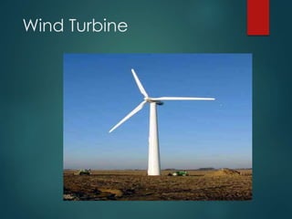

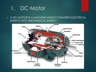
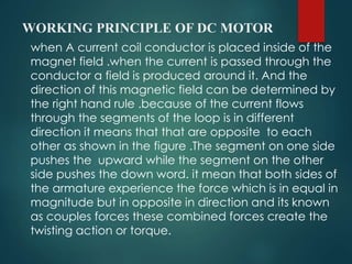
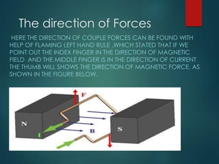
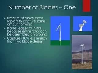
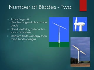
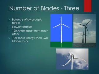
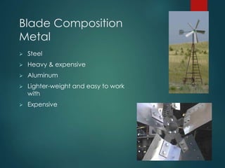
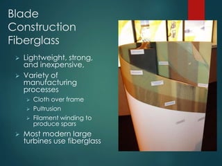
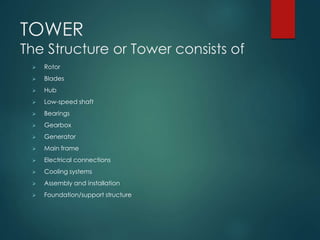
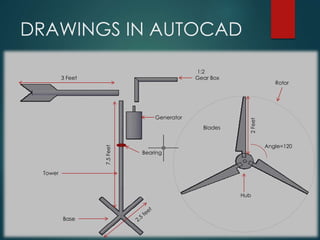
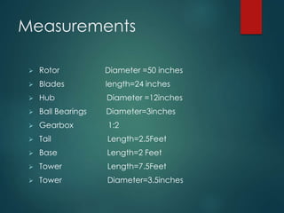
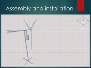
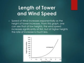
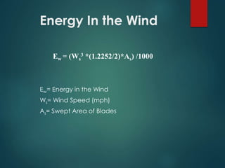
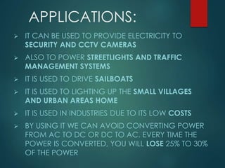


This document describes the design and components of a wind turbine generator. It contains sections on the basic components of a wind turbine - the DC motor, blades, and tower. It explains that a DC motor is used to convert the kinetic energy of the wind into mechanical energy. Common wind turbine designs use either two or three blades attached to a hub. The tower raises the rotor and blades to heights with higher wind speeds. Diagrams and specifications are provided for a sample 3-foot wind turbine design, including dimensions, a gearbox ratio, and intended applications for power generation.