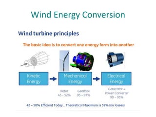
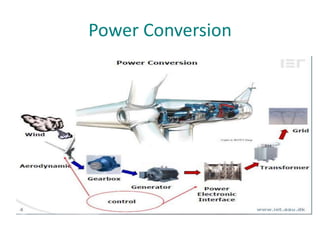
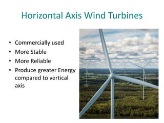
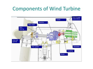
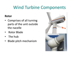
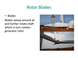
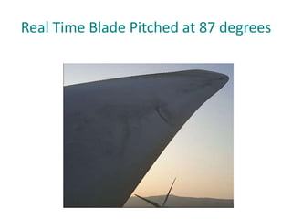
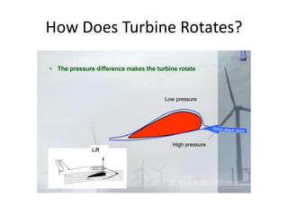
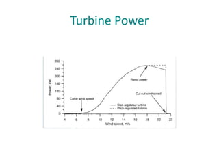
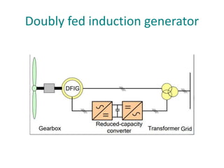
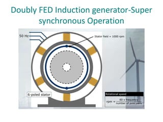
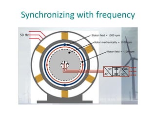
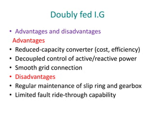
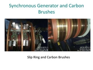
Operation and Maintenance of
Wind Turbines
Speakers
Abdullah Aftab Asjad Ali
(O&M Engr SGRE) (O&M Engr SGRE)
Introduction
• Wind turbines - a successful technology for
clean and safe production of electricity.
• Fastest growing renewable energy source.
• Globally recognized as environment friendly
and sustainable.
• Emerging as a economically competitive
source of energy.
• Wind energy will never run out, and is very
helpful in mitigating CO2 production.
Wind as a source of energy
• Wind is air in motion.
• It has a mass.
• A mass in motion has a
momentum
• Momentum is a form of
energy that can be
harvested.
• Wind energy relies on
sun. Wind is created by
uneven heating of the
earth’s surface.
Global creation of Winds
• Uneven heating of the
earth's surface. When
sun hits one part of the
earth more directly, it
warms that part up. The
warm air rises and
cooler air rushes in,
creating wind.
Kinetic Energy in the Wind
• Kinetic Energy = Work = ½mV^2
• Where:
• M= mass of moving object
• V = velocity of moving object
What is the mass of moving air?
density (ρ) x volume (Area x distance) = ρ x A x d
= (kg/m3 ) (m2 ) (m) = kg
Power in the Wind
• Power = Work / time
= Kinetic Energy / time = ½mV2 / t
= ½(ρAd)V2 /t
= ½ρAV2 (d/t) = ½ρAV3 d/t = V
Power in the Wind = ½ρAV3
• Power in the Wind =
½ρAV3
• Swept Area – A = πR2
(m2 ) Area of the circle
swept by the rotor.
• ρ = air density – in
Pakistan its about
1.225-kg/m3.
The Betz Limit
• A maximum of 59.26% of the available wind
power can be converted to mechanical power
at ideal conditions
Wind Energy Conversion
Power Conversion
Vertical Axis Wind Turbines
Horizontal Axis Wind Turbines
• Commercially used
• More Stable
• More Reliable
• Produce greater Energy
compared to vertical
axis
Mechanical-Electrical Single Line
Diagram
Components of Wind Turbine
Wind Turbine Components
• Rotor, or blades, which convert the wind's
energy into rotational shaft energy.
• Nacelle (enclosure) containing a drive train,
usually including a gearbox (Some turbines
operate without a gearbox) and a generator.
Tower, to support the rotor and drive train.
• Electronic equipment such as controls,
electrical cables, ground support equipment,
and interconnection equipment.
Wind Turbine Components
Rotor
• Comprises of all turning
parts of the unit outside
the nacelle
• Rotor Blade
• The hub
• Blade pitch mechanism
Rotor Blades
• Blades
Blades sweep around air
and further rotate shaft
which in turn rotates
generator rotor.
Real Time Blade Pitched at 87 degrees
How Does Turbine Rotates?
Turbine Power
Power Control of Turbine
Power Control through Aerodynamic
(Angle of attack, Pitch angle, Lift & Drag)
• Stall control
• Pitch control
Power Control of Turbine
Pitch Control
• Pitch controls adjust the
blades in wind turbines by
rotating them so that they use
the right fraction of the
available wind energy to get
the most power output, all the
while ensuring the turbine
does not exceed its maximum
rotational speed. This
maintains the turbine’s safety
in the event of high winds, loss
of electrical load, or other
catastrophic events.
Stall Control
• Blades are fixed at a
specific pitch angle and
start to stall in case of
high wind
ROTOR BLADE-MATERIAL
Materials
Al, Titanium, Steel, Fiber reinforced composite material
Fiber reinforced composite
Material blades currently used in almost all WT structure
Types:
Glass fiber
Carbon fiber
Organic aramid fiber (Kevlar)
Mostly used is glass fiber -Strength properties are
extraordinarily high
Carbon fibers
• Has longest tearing strength
• High modules of elasticity
• The stiffness of carbon fiber
components is comparable to that of
steel
• Fatigue properties are good
Number of Blades
• Most common design is the three-bladed turbine. The
most important reason is the stability of the turbine. A
rotor with an odd number of rotor blades (and at least
three blades) can be considered to be similar to a disc
when calculating the dynamic properties of the
machine.
• A rotor with an even number of blades will give
stability problems for a machine with a stiff structure.
The reason is that at the very moment when the
uppermost blade bends backwards, because it gets the
maximum power from the wind, the lowermost blade
passes into the wind shade in front of the tower.
Hub Of Turbines
• All major parts fixed
relative to the main
shaft in which blade
pitch can be varied no
other blade motion is
allowed
• The main body of the
rigid hub casting or
weldment to which the
blades are attached.
Inner Hub of Wind Turbines
Inner Hub of wind turbines
Drive Train
Complete wind turbine drive train consist of
all the rotating components
• 1. Main shaft
• 2. Coupling
• 3. Gearbox
• 4. Brake
• 5. Generator
Shaft
• Cylindrical element designed to rotate
• Transmit torque
• Attached to the gear pulley and couplings
• Wind turbine shafts are especially found in
gearboxes, generators and linkages.
MAIN SHAFT / LOW SPEED SHAFT /
ROTOR SHAFT
• Transfer torque from
the rotor to the rest of
the drive train and
transfer of all other
loads to the nacelle
structure
• Supports the weight of
the rotor
• Made of steel
Low Speed Shaft
High Shaft
• Connecting shaft of the
gearbox outlet to the
electric generator
rotates with nominal
speed of 1500 RPM
• Fitted with flexible
coupling at each end to
cater for small
misalignment between
generator and gearbox
High Speed Shaft
PLANETARY GEARBOX
• Input and output shafts
are co-axial
• There are multiple
pairs of gear teeth
meshing at anytime
• Loads on each gear
reduced
Planetary Gearbox
• Planet carrier rotates with the same carrier arm
rotational speed of the rotor blades
• Three planet wheel turn around inner
circumference of the ring wheel
• Increase the speed of the sun wheel
Advantages:
• Always three gear wheels supporting each other
and that all gear wheels are engaged at the time
• in principle it only needs to about a 1/3 of the
size
Doubly fed induction generator
Doubly FED Induction generator-Super
synchronous Operation
Synchronizing with frequency
Doubly fed induction generator
• The configuration known as DFIG (Double fed induction
generator) correspond to the WRIG (Wound rotor induction
generator) with partial scale frequency converter
• The partial scale frequency converter performs the reactive
power compensation and ensures smoother grid
connection
• The generator has a wider range of speed control, e.g., (-
40% to +30%) around the synchronous speed (wider than
OptiSlip)
• The use of slip rings and protection in case of grid faults is
a major drawback
• Variable speed operation is obtained by injecting a
controllable voltage into the rotor at the desired frequency
Doubly fed I.G
• Advantages and disadvantages
Advantages
• Reduced-capacity converter (cost, efficiency)
• Decoupled control of active/reactive power
• Smooth grid connection
• Disadvantages
• Regular maintenance of slip ring and gearbox
• Limited fault ride-through capability
Synchronous Generator and Carbon
Brushes
Slip Ring and Carbon Brushes
Control and Protection systems
• Increasing use of advanced electronics for
• Generator, converter and power control
• Pitch system
• Start, stop and sequencing
• Surveillance
Why do we need a control!
• The primary energy source is non linear and
unpredictable. Increase in wind speed develops
an enormous power in rotor – To be optimized
• To transfer the electrical power to the grid at an
imposed level, for wide range of wind velocities.
• To meet power quality requirements
• To detect the abnormal conditions and
preventing the wind turbine from possible
dangerous situations
• Achieve desired function and Safe Operation
Control system
• Control system consists of
• Various sensors, Transducers and Limit
switches (input)
• PLC (Process)
• Circuit breakers, Converters, contactors and
relays (output)
• Set point list
Important functions of Control system
• Alignment to the wind by Yawing
• Start-up and shutdown procedure
• Connection of the electrical load
• Rotor speed Control
• Power limitation
• Cable twist limits
• Temperature control
General Sequence
PROTECTION SYSTEM
• Over-speed
• Generator overload or fault
• Excessive vibration
• Abnormal cable Twist
NACELLE
• The nacelle cover is the wind turbine housing
Protects turbine components from weather
• Reduces emitted mechanical sound Material
• G-FRC glass-fiber reinforced composite
materials
• On larger Machines it has a hole that it can be
entered personal for inspector (or) maintains
the internal components.
Inside of a Nacelle
Inside of a nacelle
Main Frame
• Transfer the rotor loading to the yaw bearing
and to provide mountings for the gearbox and
generator
• Either welded beam or casted
Yaw Control
• Rotate the nacelle with respect to the tower
on its slew bearing
• Keep the turbine facing in the wind
• Unwind the power and other cables – Wind
Vane on nacelle tells controller which way to
point rotor into the wind – Yaw drive turns
gears to point rotor into wind
Yaw Drive
• Rotate the nacelle with
respect to the tower on
its slew bearing
• Keep the turbine facing
in the wind unwind the
power and other cables
Yaw clamps and Yaw Drive
• Yaw clamps acts as
break and keep the
nacelle at fixed
position.
Converter Cabinet
• A power electronic converter
enables efficient conversion of
the variable frequency output
of an induction generator,
driven by a variable speed
wind turbine, to a fixed
frequency appropriate for the
grid or a load..
• All the power is transmitted to
the grid through the converter.
The converter tracks the
frequency and phases of grid
voltage to keep the output
current and frequency of
turbines in consistent with
those of the grid
Converter Cabinet
Tower
• Made from tubular steel,
the tower supports the
structure of the turbine.
Towers usually come in
three sections and are
assembled on-site.
Because wind speed
increases with height,
taller towers enable
turbines to capture more
energy and generate
more electricity.
Towers
• Towers are stacked
upon one another
• Mostly there are more
than one parts of a
tower fastened to one
another with huge bolts
Operations and Maintenance of
Turbines
Maintenance of wind turbines involve
• Tensioning of blades bolts
• Torquing of all the towers bolts, main frame,
main shaft disc, generator feet etc.
• Greasing of Generator, yaw teeth's.
• Cleaning of Fiber and Platforms
Tensioning of blades
• During Tensioning of Blades a
pressure of 1000 bar using a
Tensioner pump is given and
bolts are tightened that are
loose before any catastrophe
happens.
• When pressure is applied on
the bolt, the tensioner pulls
the bolt upwards and using
ratchet bolts are tightened.
• Precautions are important
when dealing with such high
pressure, a little mistake can
put your or others life in
jeopardy.
Torquing of bolts
• Using different Keys at different
pressures, the bolts in the tower
and inside the nacelle are
tightened
• For the first tower, the pressure is
425 bar and 400 bar onwards for
remaining, the yaw tower is
tightened at 374 bars.
• Inside the nacelle, the bolts of
main frame are tightened at 500
bars and there are different
pressures for other bolts.
• Different RT’s mainly RT 5, RT3
and RT2 are used with different
key sizes mainly 36, 27, 46
depending upon the size of bolt.
Greasing of blades, yaw teeth and
Generator and cleaning
• Greasing of yaw teeth,
Blades and generator is
done after 3 months and
6 months. This is known
as 3M/6M maintenance.
• Cleaning of wind turbine
is very important as the
dirt particles can lead to a
lot of warnings and
alarming situations on
turbine.
Operations in Wind Turbine
There are number of alarms that can occur on
turbine, and they are the major reason for
availability loss of any wind turbine. So, it is very
important to keep the turbine on going and
available for power production. Some alarms are
removed using SCADA, but some are removed
by fixing the fault or any intricacy on turbine.
SCADA
Real time instantaneous data
of wind turbines is monitored
an analyzed. Any abnormality
is observed and removed.
Operators monitor wind
turbine production 24/7.
Total Wind Capacity of Pakistan
• Currently, 1836 MW of power is being
produced from wind in Pakistan while Pakistan
has more than 132,000 MW capacity on wind
including both off shore and on shore.
• The recent wind Plants that are set up in
Pakistan has each turbine with capacity of 2.1
MW power production.
• Wind is the second most biggest source of
clean energy in the World.
Wind Map of Pakistan
THANKS For Your Time

Wind Turbine operation & Maintenance.pptx

  • 1.
    Operation and Maintenanceof Wind Turbines Speakers Abdullah Aftab Asjad Ali (O&M Engr SGRE) (O&M Engr SGRE)
  • 2.
    Introduction • Wind turbines- a successful technology for clean and safe production of electricity. • Fastest growing renewable energy source. • Globally recognized as environment friendly and sustainable. • Emerging as a economically competitive source of energy. • Wind energy will never run out, and is very helpful in mitigating CO2 production.
  • 3.
    Wind as asource of energy • Wind is air in motion. • It has a mass. • A mass in motion has a momentum • Momentum is a form of energy that can be harvested. • Wind energy relies on sun. Wind is created by uneven heating of the earth’s surface.
  • 4.
    Global creation ofWinds • Uneven heating of the earth's surface. When sun hits one part of the earth more directly, it warms that part up. The warm air rises and cooler air rushes in, creating wind.
  • 5.
    Kinetic Energy inthe Wind • Kinetic Energy = Work = ½mV^2 • Where: • M= mass of moving object • V = velocity of moving object What is the mass of moving air? density (ρ) x volume (Area x distance) = ρ x A x d = (kg/m3 ) (m2 ) (m) = kg
  • 6.
    Power in theWind • Power = Work / time = Kinetic Energy / time = ½mV2 / t = ½(ρAd)V2 /t = ½ρAV2 (d/t) = ½ρAV3 d/t = V Power in the Wind = ½ρAV3
  • 7.
    • Power inthe Wind = ½ρAV3 • Swept Area – A = πR2 (m2 ) Area of the circle swept by the rotor. • ρ = air density – in Pakistan its about 1.225-kg/m3.
  • 8.
    The Betz Limit •A maximum of 59.26% of the available wind power can be converted to mechanical power at ideal conditions
  • 9.
  • 10.
  • 11.
  • 12.
    Horizontal Axis WindTurbines • Commercially used • More Stable • More Reliable • Produce greater Energy compared to vertical axis
  • 13.
  • 14.
  • 15.
    Wind Turbine Components •Rotor, or blades, which convert the wind's energy into rotational shaft energy. • Nacelle (enclosure) containing a drive train, usually including a gearbox (Some turbines operate without a gearbox) and a generator. Tower, to support the rotor and drive train. • Electronic equipment such as controls, electrical cables, ground support equipment, and interconnection equipment.
  • 16.
    Wind Turbine Components Rotor •Comprises of all turning parts of the unit outside the nacelle • Rotor Blade • The hub • Blade pitch mechanism
  • 17.
    Rotor Blades • Blades Bladessweep around air and further rotate shaft which in turn rotates generator rotor.
  • 18.
    Real Time BladePitched at 87 degrees
  • 19.
  • 20.
  • 21.
    Power Control ofTurbine Power Control through Aerodynamic (Angle of attack, Pitch angle, Lift & Drag) • Stall control • Pitch control
  • 22.
    Power Control ofTurbine Pitch Control • Pitch controls adjust the blades in wind turbines by rotating them so that they use the right fraction of the available wind energy to get the most power output, all the while ensuring the turbine does not exceed its maximum rotational speed. This maintains the turbine’s safety in the event of high winds, loss of electrical load, or other catastrophic events.
  • 23.
    Stall Control • Bladesare fixed at a specific pitch angle and start to stall in case of high wind
  • 24.
    ROTOR BLADE-MATERIAL Materials Al, Titanium,Steel, Fiber reinforced composite material Fiber reinforced composite Material blades currently used in almost all WT structure Types: Glass fiber Carbon fiber Organic aramid fiber (Kevlar) Mostly used is glass fiber -Strength properties are extraordinarily high
  • 25.
    Carbon fibers • Haslongest tearing strength • High modules of elasticity • The stiffness of carbon fiber components is comparable to that of steel • Fatigue properties are good
  • 26.
    Number of Blades •Most common design is the three-bladed turbine. The most important reason is the stability of the turbine. A rotor with an odd number of rotor blades (and at least three blades) can be considered to be similar to a disc when calculating the dynamic properties of the machine. • A rotor with an even number of blades will give stability problems for a machine with a stiff structure. The reason is that at the very moment when the uppermost blade bends backwards, because it gets the maximum power from the wind, the lowermost blade passes into the wind shade in front of the tower.
  • 27.
    Hub Of Turbines •All major parts fixed relative to the main shaft in which blade pitch can be varied no other blade motion is allowed • The main body of the rigid hub casting or weldment to which the blades are attached.
  • 28.
    Inner Hub ofWind Turbines
  • 29.
    Inner Hub ofwind turbines
  • 30.
    Drive Train Complete windturbine drive train consist of all the rotating components • 1. Main shaft • 2. Coupling • 3. Gearbox • 4. Brake • 5. Generator
  • 31.
    Shaft • Cylindrical elementdesigned to rotate • Transmit torque • Attached to the gear pulley and couplings • Wind turbine shafts are especially found in gearboxes, generators and linkages.
  • 32.
    MAIN SHAFT /LOW SPEED SHAFT / ROTOR SHAFT • Transfer torque from the rotor to the rest of the drive train and transfer of all other loads to the nacelle structure • Supports the weight of the rotor • Made of steel
  • 33.
  • 34.
    High Shaft • Connectingshaft of the gearbox outlet to the electric generator rotates with nominal speed of 1500 RPM • Fitted with flexible coupling at each end to cater for small misalignment between generator and gearbox
  • 35.
  • 36.
    PLANETARY GEARBOX • Inputand output shafts are co-axial • There are multiple pairs of gear teeth meshing at anytime • Loads on each gear reduced
  • 37.
    Planetary Gearbox • Planetcarrier rotates with the same carrier arm rotational speed of the rotor blades • Three planet wheel turn around inner circumference of the ring wheel • Increase the speed of the sun wheel Advantages: • Always three gear wheels supporting each other and that all gear wheels are engaged at the time • in principle it only needs to about a 1/3 of the size
  • 38.
  • 39.
    Doubly FED Inductiongenerator-Super synchronous Operation
  • 40.
  • 41.
    Doubly fed inductiongenerator • The configuration known as DFIG (Double fed induction generator) correspond to the WRIG (Wound rotor induction generator) with partial scale frequency converter • The partial scale frequency converter performs the reactive power compensation and ensures smoother grid connection • The generator has a wider range of speed control, e.g., (- 40% to +30%) around the synchronous speed (wider than OptiSlip) • The use of slip rings and protection in case of grid faults is a major drawback • Variable speed operation is obtained by injecting a controllable voltage into the rotor at the desired frequency
  • 42.
    Doubly fed I.G •Advantages and disadvantages Advantages • Reduced-capacity converter (cost, efficiency) • Decoupled control of active/reactive power • Smooth grid connection • Disadvantages • Regular maintenance of slip ring and gearbox • Limited fault ride-through capability
  • 43.
    Synchronous Generator andCarbon Brushes Slip Ring and Carbon Brushes
  • 44.
    Control and Protectionsystems • Increasing use of advanced electronics for • Generator, converter and power control • Pitch system • Start, stop and sequencing • Surveillance
  • 45.
    Why do weneed a control! • The primary energy source is non linear and unpredictable. Increase in wind speed develops an enormous power in rotor – To be optimized • To transfer the electrical power to the grid at an imposed level, for wide range of wind velocities. • To meet power quality requirements • To detect the abnormal conditions and preventing the wind turbine from possible dangerous situations • Achieve desired function and Safe Operation
  • 46.
    Control system • Controlsystem consists of • Various sensors, Transducers and Limit switches (input) • PLC (Process) • Circuit breakers, Converters, contactors and relays (output) • Set point list
  • 47.
    Important functions ofControl system • Alignment to the wind by Yawing • Start-up and shutdown procedure • Connection of the electrical load • Rotor speed Control • Power limitation • Cable twist limits • Temperature control
  • 48.
  • 49.
    PROTECTION SYSTEM • Over-speed •Generator overload or fault • Excessive vibration • Abnormal cable Twist
  • 50.
    NACELLE • The nacellecover is the wind turbine housing Protects turbine components from weather • Reduces emitted mechanical sound Material • G-FRC glass-fiber reinforced composite materials • On larger Machines it has a hole that it can be entered personal for inspector (or) maintains the internal components.
  • 51.
    Inside of aNacelle
  • 52.
    Inside of anacelle
  • 53.
    Main Frame • Transferthe rotor loading to the yaw bearing and to provide mountings for the gearbox and generator • Either welded beam or casted
  • 54.
    Yaw Control • Rotatethe nacelle with respect to the tower on its slew bearing • Keep the turbine facing in the wind • Unwind the power and other cables – Wind Vane on nacelle tells controller which way to point rotor into the wind – Yaw drive turns gears to point rotor into wind
  • 55.
    Yaw Drive • Rotatethe nacelle with respect to the tower on its slew bearing • Keep the turbine facing in the wind unwind the power and other cables
  • 56.
    Yaw clamps andYaw Drive • Yaw clamps acts as break and keep the nacelle at fixed position.
  • 57.
    Converter Cabinet • Apower electronic converter enables efficient conversion of the variable frequency output of an induction generator, driven by a variable speed wind turbine, to a fixed frequency appropriate for the grid or a load.. • All the power is transmitted to the grid through the converter. The converter tracks the frequency and phases of grid voltage to keep the output current and frequency of turbines in consistent with those of the grid
  • 58.
  • 59.
    Tower • Made fromtubular steel, the tower supports the structure of the turbine. Towers usually come in three sections and are assembled on-site. Because wind speed increases with height, taller towers enable turbines to capture more energy and generate more electricity.
  • 60.
    Towers • Towers arestacked upon one another • Mostly there are more than one parts of a tower fastened to one another with huge bolts
  • 61.
    Operations and Maintenanceof Turbines Maintenance of wind turbines involve • Tensioning of blades bolts • Torquing of all the towers bolts, main frame, main shaft disc, generator feet etc. • Greasing of Generator, yaw teeth's. • Cleaning of Fiber and Platforms
  • 62.
    Tensioning of blades •During Tensioning of Blades a pressure of 1000 bar using a Tensioner pump is given and bolts are tightened that are loose before any catastrophe happens. • When pressure is applied on the bolt, the tensioner pulls the bolt upwards and using ratchet bolts are tightened. • Precautions are important when dealing with such high pressure, a little mistake can put your or others life in jeopardy.
  • 63.
    Torquing of bolts •Using different Keys at different pressures, the bolts in the tower and inside the nacelle are tightened • For the first tower, the pressure is 425 bar and 400 bar onwards for remaining, the yaw tower is tightened at 374 bars. • Inside the nacelle, the bolts of main frame are tightened at 500 bars and there are different pressures for other bolts. • Different RT’s mainly RT 5, RT3 and RT2 are used with different key sizes mainly 36, 27, 46 depending upon the size of bolt.
  • 64.
    Greasing of blades,yaw teeth and Generator and cleaning • Greasing of yaw teeth, Blades and generator is done after 3 months and 6 months. This is known as 3M/6M maintenance. • Cleaning of wind turbine is very important as the dirt particles can lead to a lot of warnings and alarming situations on turbine.
  • 65.
    Operations in WindTurbine There are number of alarms that can occur on turbine, and they are the major reason for availability loss of any wind turbine. So, it is very important to keep the turbine on going and available for power production. Some alarms are removed using SCADA, but some are removed by fixing the fault or any intricacy on turbine.
  • 66.
    SCADA Real time instantaneousdata of wind turbines is monitored an analyzed. Any abnormality is observed and removed. Operators monitor wind turbine production 24/7.
  • 67.
    Total Wind Capacityof Pakistan • Currently, 1836 MW of power is being produced from wind in Pakistan while Pakistan has more than 132,000 MW capacity on wind including both off shore and on shore. • The recent wind Plants that are set up in Pakistan has each turbine with capacity of 2.1 MW power production. • Wind is the second most biggest source of clean energy in the World.
  • 68.
    Wind Map ofPakistan
  • 69.