Downloaded 779 times

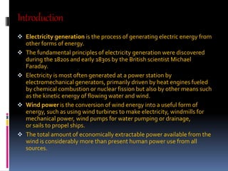
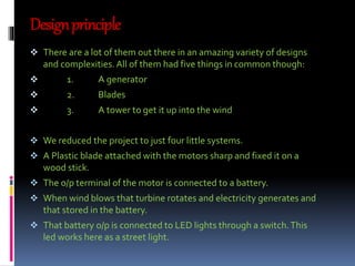
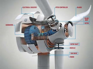


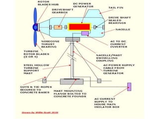


The document discusses the design and components of a wind turbine for power generation. It describes the key parts of a wind turbine including the generator, blades, hub, tower, and how it is connected to the electric grid. The generator converts the kinetic energy of the rotating blades into electrical energy. Blades are made of composite materials and their shape and count are optimized for aerodynamic efficiency. The tower needs to be tall to access stronger winds higher above the ground.