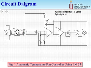
AUTOMATIC TEMPERATURE
FAN CONTROLLER
AUTOMATIC TEMPERATURE
FAN CONTROLLER
Presenter:
MUHAMMAD FAZIL MEMON
Batch: 2016
Presented to:
Engr. LATIF SHAH
FACULTY OF ENGINEERING,SCIENCE AND TECHNOLOGY
(FEST) INDUS UNIVERSITY
ContentsContents
 Abstract
 Introduction
 Methodology
 Results
 Cost
 Conclusion
 References
AbstractAbstract
 This project is based on the working of temperature controller
using LM35 and fan as cooler. The circuit automatically senses
the temperature and works normally within a particular
temperature ranges.
 VR of 33k is using which the temperature can be controlled with
the help of a LM35 temperature sensor.
 
IntroductionIntroduction
 This project is based on the working of temperature
controller using LM35 and fan as cooler. The circuit
automatically senses the temperature and works
normally within a particular temperature range.
MethodologyMethodology
• It comprises of a LM35, comparator, relay and a reference
voltage to set the reference temperature.
 LM35: Temperature sensor which is calibrated in the Celsius
(Centigrade) scale with a linear degree to volt conversion.
Comparator :An accurate comparator (A1 of LM358) in order to
construct a complete thermal-controlled switch Reference
voltage.
 The preset (VR1) & resistor (R3) from a variable voltage
divider which sets a reference voltage (V ref) form 0V ~ 1.62V.
The op-amp (A2) buffers the reference voltage so as to avoid
loading the divider network (VR1 &R3).Relay.
 The circuit switches a miniature relay ON or OFF
according to the temperature
detected by the single chip temperature sensor LM35DZ.
 When the LM35DZ detects atemperature higher than the
preset level (set by VR1), the relay is actuated. When
the temperature falls below the preset temperature, relay
is de-energized.
MethodologyMethodology
Circuit DaigramCircuit Daigram
Fig. 1 Automatic Temperature Fan Controller Using LM 35Fig. 1 Automatic Temperature Fan Controller Using LM 35
 IC1: LM35
 DZ Precision Celsius (Centigrade) Temperature sensor 
 LM358
 Dual single supply Op-amp.
 Q1:
 General purpose PNP transistor ( A1015,...) with E-C-B pin-out
 D1, D2:
 1N4148 silicon diodes (or 1SS133)
  D3, D4:
 1N400x (x=2,,,,.7) rectifier diodes
 ZD1:
 Zener diode, 13V, 400mW
 Preset
 (trim pot)
 2.2K
 (Temperature set point) 
 (# 222 or 2k2)
List of ComponentsList of Components
 2.2K
 (Temperature set point) 
 (# 222 or 2k2
 Resistors:
 ( 1/4W or 1/6W)
  R1 -- 470K
  R2 – 68K
  R3 -- 33K
  R4 -- 10K
  VR -- 10K
  Capacitors:
  C1 -- 100 nF
  C2 -- 1 µF
List of ComponentsList of Components
Fig. 2 Pin diagram of LM358 OP-AMPFig. 2 Pin diagram of LM358 OP-AMP
LM 35LM 35
 After designing, simulating, assembling, soldering and
testing the circuit, we came to the conclusion that our
circuit of the temperature based fan speed controller is
working satisfactorily.
 The construction hardware perfect.
 The total project work perfectly and has negligible
amount of unexpected functioning.
ResultsResults
Components Price
Resistors 50
Capacitors 70
Operational Amplifiers OPM 50
Transformer 150
Vero Board 100
Diodes 30
LM 35 IC 50
Power Supply Cable 30
BJT Transistor 20
DC Motor 150
TOTAL 700
CostCost
 [1]https://www.scribd.com/doc/110380630/Automatic-
Temperature-Controller-Using-Lm35
RefrencesRefrences
 The problem statement is implemented.
 Hardware part is halfway implemented.
 As the technology is going on developing day by
day, we prefer things to be done automatically and
in the same way our projects reduces the work to
mankind.
ConclusionConclusion

AUTOMATIC TEMPERATURE FAN CONTROLLER

  • 1.
    AUTOMATIC TEMPERATURE FAN CONTROLLER AUTOMATICTEMPERATURE FAN CONTROLLER Presenter: MUHAMMAD FAZIL MEMON Batch: 2016 Presented to: Engr. LATIF SHAH FACULTY OF ENGINEERING,SCIENCE AND TECHNOLOGY (FEST) INDUS UNIVERSITY
  • 2.
    ContentsContents  Abstract  Introduction Methodology  Results  Cost  Conclusion  References
  • 3.
    AbstractAbstract  This projectis based on the working of temperature controller using LM35 and fan as cooler. The circuit automatically senses the temperature and works normally within a particular temperature ranges.  VR of 33k is using which the temperature can be controlled with the help of a LM35 temperature sensor.  
  • 4.
    IntroductionIntroduction  This projectis based on the working of temperature controller using LM35 and fan as cooler. The circuit automatically senses the temperature and works normally within a particular temperature range.
  • 5.
    MethodologyMethodology • It comprisesof a LM35, comparator, relay and a reference voltage to set the reference temperature.  LM35: Temperature sensor which is calibrated in the Celsius (Centigrade) scale with a linear degree to volt conversion. Comparator :An accurate comparator (A1 of LM358) in order to construct a complete thermal-controlled switch Reference voltage.  The preset (VR1) & resistor (R3) from a variable voltage divider which sets a reference voltage (V ref) form 0V ~ 1.62V. The op-amp (A2) buffers the reference voltage so as to avoid loading the divider network (VR1 &R3).Relay.
  • 6.
     The circuitswitches a miniature relay ON or OFF according to the temperature detected by the single chip temperature sensor LM35DZ.  When the LM35DZ detects atemperature higher than the preset level (set by VR1), the relay is actuated. When the temperature falls below the preset temperature, relay is de-energized. MethodologyMethodology
  • 7.
    Circuit DaigramCircuit Daigram Fig.1 Automatic Temperature Fan Controller Using LM 35Fig. 1 Automatic Temperature Fan Controller Using LM 35
  • 8.
     IC1: LM35 DZ Precision Celsius (Centigrade) Temperature sensor   LM358  Dual single supply Op-amp.  Q1:  General purpose PNP transistor ( A1015,...) with E-C-B pin-out  D1, D2:  1N4148 silicon diodes (or 1SS133)   D3, D4:  1N400x (x=2,,,,.7) rectifier diodes  ZD1:  Zener diode, 13V, 400mW  Preset  (trim pot)  2.2K  (Temperature set point)   (# 222 or 2k2) List of ComponentsList of Components
  • 9.
     2.2K  (Temperatureset point)   (# 222 or 2k2  Resistors:  ( 1/4W or 1/6W)   R1 -- 470K   R2 – 68K   R3 -- 33K   R4 -- 10K   VR -- 10K   Capacitors:   C1 -- 100 nF   C2 -- 1 µF List of ComponentsList of Components
  • 10.
    Fig. 2 Pindiagram of LM358 OP-AMPFig. 2 Pin diagram of LM358 OP-AMP LM 35LM 35
  • 11.
     After designing,simulating, assembling, soldering and testing the circuit, we came to the conclusion that our circuit of the temperature based fan speed controller is working satisfactorily.  The construction hardware perfect.  The total project work perfectly and has negligible amount of unexpected functioning. ResultsResults
  • 12.
    Components Price Resistors 50 Capacitors70 Operational Amplifiers OPM 50 Transformer 150 Vero Board 100 Diodes 30 LM 35 IC 50 Power Supply Cable 30 BJT Transistor 20 DC Motor 150 TOTAL 700 CostCost
  • 13.
  • 14.
     The problemstatement is implemented.  Hardware part is halfway implemented.  As the technology is going on developing day by day, we prefer things to be done automatically and in the same way our projects reduces the work to mankind. ConclusionConclusion