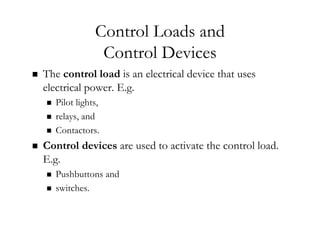
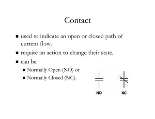
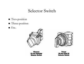
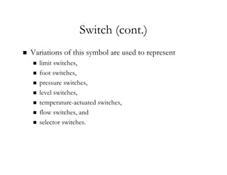
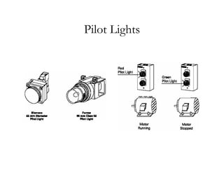
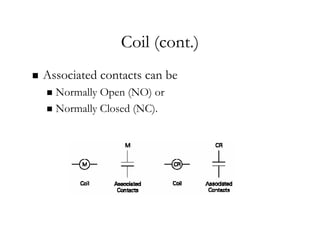
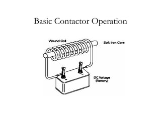
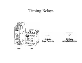
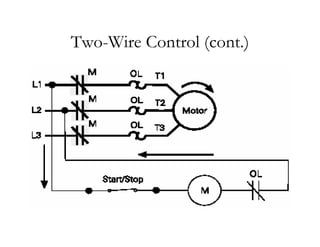
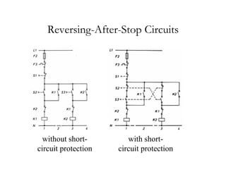
Basics of Control
Basics of Control
Components
Components
INC 100
INC 100 Electrotechnology
Electrotechnology
Assist. Prof. Pakorn
Assist. Prof. Pakorn Kaewtrakulpong
Kaewtrakulpong, Ph.D.
, Ph.D.
INC, KMUTT
INC, KMUTT
Objectives
Objectives
„
„ State the purpose and general
State the purpose and general principles
principles of
of control
control
components
components and
and circuits
circuits
„
„ Identify various
Identify various symbols
symbols which represent control
which represent control
components
components
„
„ Read a basic
Read a basic line diagram
line diagram
„
„ Describe the construction and operating principles of
Describe the construction and operating principles of
magnetic contactors
magnetic contactors and
and control relays
control relays
Control Loads and
Control Loads and
Control Devices
Control Devices
„
„ The
The control load
control load is an electrical device that uses
is an electrical device that uses
electrical power. E.g.
„
„ Pilot lights,
Pilot lights,
„
„ relays, and
relays, and
„
„ Contactors.
Contactors.
„
„ Control devices
Control devices are used to activate the control load.
are used to activate the control load.
E.g.
E.g.
„
„ Pushbuttons and
Pushbuttons and
„
„ switches.
switches.
Electrical Symbols
Electrical Symbols
„
„ Contact
Contact
„
„ Switch
Switch
„
„ Pushbutton
Pushbutton
„
„ Coil
Coil
„
„ Overload Relay
Overload Relay
„
„ Pilot Light
Pilot Light
„
„ etc
etc
Contact
Contact
„
„ used to indicate an
used to indicate an open or closed path of
open or closed path of
current flow
current flow.
.
„
„ require an action to change their
require an action to change their state
state.
.
„
„ can be
can be
„
„ Normally Open (
Normally Open (NO
NO) or
) or
„
„ Normally Closed (
Normally Closed (NC
NC).
).
Switch
Switch
„
„ also used to indicate an
also used to indicate an open or closed path of
open or closed path of
current flow
current flow.
.
„
„ require another device or action to change their
require another device or action to change their
state
state.
.
„
„ can be
can be
„
„ Normally Open (
Normally Open (NO
NO) or
) or
„
„ Normally Closed (
Normally Closed (NC
NC).
).
Selector Switch
Selector Switch
„
„ Two
Two-
-position
position
„
„ Three
Three-
-position
position
„
„ Etc.
Etc.
Switch (cont.)
Switch (cont.)
„
„ Variations of this symbol are used to represent
Variations of this symbol are used to represent
„
„ limit
limit switches,
switches,
„
„ foot
foot switches,
switches,
„
„ pressure
pressure switches,
switches,
„
„ level
level switches,
switches,
„
„ temperature
temperature-
-actuated
actuated switches,
switches,
„
„ flow
flow switches, and
switches, and
„
„ selector
selector switches.
switches.
Pushbutton
Pushbutton
Pushbutton (cont.)
Pushbutton (cont.)
„
„ 2 basic types of pushbuttons:
2 basic types of pushbuttons:
„
„ momentary
momentary
„
„ maintained
maintained (latches in place when the button is
(latches in place when the button is
pressed.)
pressed.)
„
„ can be
can be
„
„ Normally Open (
Normally Open (NO
NO) or
) or
„
„ Normally Closed (
Normally Closed (NC
NC).
).
Pilot Lights
Pilot Lights
Pilot Light
Pilot Light
„
„ a small electric light used to indicate a specific
a small electric light used to indicate a specific
condition of a circuit.
„
„ E.g., a red light might be used to indicate a motor is
E.g., a red light might be used to indicate a motor is
running.
running.
„
„ The
The letter
letter in the center of the pilot light symbol
in the center of the pilot light symbol
indicates the
indicates the color
color of the light.
of the light.
Control Relays
Control Relays
Control Relays (cont.)
„
„ Relays are widely used in
Relays are widely used in control circuits
control circuits.
.
„
„ They are used
They are used
„
„ for switching multiple control circuits and
for switching multiple control circuits and
„
„ for
for controlling light loads
controlling light loads e.g. starting coils, pilot
e.g. starting coils, pilot
lights, and audible alarms.
Relay Operation
Relay Operation
Coil
Coil
„
„ used in
used in electromagnetic starters
electromagnetic starters,
, contactors
contactors, and
, and
relays
relays.
.
„
„ The purpose of
The purpose of contactors
contactors and
and relays
relays is to open
is to open
and close
and close associated contacts
associated contacts.
.
„
„ A letter is used to designate the
A letter is used to designate the coil
coil; the
; the
associated
associated contacts
contacts have the
have the same identifying
same identifying
letter
letter.
.
Coil (cont.)
Coil (cont.)
„
„ Associated contacts
Associated contacts can be
can be
„
„ Normally Open (
Normally Open (NO
NO) or
) or
„
„ Normally Closed (
Normally Closed (NC
NC).
).
Coil Example
Coil Example
Magnetic Contactors
Magnetic Contactors
Basic Contactor Operation
Magnetic Contactors: Interior
Control Transformers
Timing Relays
Timing Relays
On
On-
-Delay, Time Closed
Delay, Time Closed
Off
Off-
-Delay, Timed Open
Delay, Timed Open
Line Diagrams
Line Diagrams
„
„ also referred to as a
also referred to as a ladder diagrams
ladder diagrams.
.
„
„ show the
show the functional
functional relationship of
relationship of
components and devices in an electrical circuit,
not
not the
the physical
physical relationship.
relationship.
„
„ made up of 2 circuits,
made up of 2 circuits,
„
„ the
the control
control circuit and
circuit and
„
„ the
the power
power circuit.
circuit.
Line Diagrams (cont.)
„
„ Electrical wires in a line diagram are represented by
Electrical wires in a line diagram are represented by
lines.
lines.
„
„ Control
Control-
-circuit
circuit wiring is represented by a
wiring is represented by a lighter
lighter-
-weight
weight
line and
line and power
power-
-circuit
circuit wiring is represented by a
wiring is represented by a heavier
heavier-
-
weight
weight line.
line.
„
„ A small
A small dot
dot or node at the intersection of 2 or more
or node at the intersection of 2 or more
wires indicates an
wires indicates an electrical connection
electrical connection.
.
„
„ Line diagrams are read from
Line diagrams are read from left to right
left to right.
.
Example: Power Circuit and Control
Circuit
Circuit
Connecting Loads and
Control Devices
Control Devices
„
„ Control circuits are made up of control loads
Control circuits are made up of control loads
and control devices.
Line Numbering
Line Numbering
Two
Two-
-Wire Control
Wire Control
„
„ A two
A two-
-wire control circuit provides
wire control circuit provides low
low-
-voltage
voltage
release
release but
but not
not low
low-
-voltage protection
voltage protection.
.
„
„ low
low-
-voltage release
voltage release
„
„ In the event of a power loss the contactor will
In the event of a power loss the contactor will
deenergize
deenergize, stopping the motor.
, stopping the motor.
„
„ However, when power is restored, the motor will
However, when power is restored, the motor will
restart without warning if the control device is still
closed.
closed.
Two
Two-
-Wire Control (cont.)
Wire Control (cont.)
„
„ This type of control scheme is used for
This type of control scheme is used for remote
remote
or
or inaccessible
inaccessible installations such as water
installations such as water-
-
treatment plants or pumping stations. In these
applications it is desirable to have an immediate
return to service when power is restored.
Two
Two-
-Wire Control (cont.)
Wire Control (cont.)
Holding Circuit
Holding Circuit
Three
Three-
-Wire Control
Wire Control
„
„ low
low-
-voltage protection
voltage protection.
.
„
„ If an overload causes the
If an overload causes the “
“OL
OL”
” contacts in the control
contacts in the control
circuit to open,
circuit to open,
„
„ the
the “
“M
M”
” coil is
coil is deenergized
deenergized and
and
„
„ the motor shut down.
the motor shut down.
„
„ When the overload is cleared,
When the overload is cleared,
„
„ the motor will not suddenly restart on its own.
the motor will not suddenly restart on its own.
„
„ An operator must depress the
An operator must depress the “
“Start
Start”
” button to restart the
button to restart the
motor.
motor.
Holding Circuit
Holding Circuit
Three
Three-
-Wire Control (cont
Wire Control (cont.)
.)
Interposing a Relay
Interposing a Relay
„
„ A 24 VAC coil may
A 24 VAC coil may not
not be
be strong enough
strong enough to
to
operate a
operate a large starter
large starter. E.g.
. E.g.
„
„ the electromagnetic coil of the
the electromagnetic coil of the “
“M
M”
” contactor
contactor
selected is rated for
selected is rated for 460 VAC
460 VAC.
.
„
„ The electromagnetic coil of the
The electromagnetic coil of the control relay
control relay (CR)
(CR)
selected is
selected is 24 VAC
24 VAC.
.
Interposing a Relay (cont.)
Schematic Diagram
Schematic Diagram
Wiring Diagram
Wiring Diagram
Some Simple Motor Control
Applications
Applications
„
„ Forward
Forward-
-Reverse Motor Control
Reverse Motor Control
„
„ Star
Star-
-Delta Motor
Delta Motor-
-Starting Control
Starting Control
Forward
Forward-
-Reverse Motor Control
Reverse Motor Control
e.g.
e.g.
„
„ Jogging circuits
Jogging circuits
„
„ Reversing
Reversing-
-after
after-
-stop
stop
circuits
circuits
Jogging Circuits
Jogging Circuits
using selector
switch
without short-
circuit protection
with short-
circuit protection
Reversing
Reversing-
-After
After-
-Stop Circuits
Stop Circuits
without short-
circuit protection
with short-
circuit protection
Star
Star-
-Delta Motor
Delta Motor-
-Starting Control
Starting Control

basic of control component description.pdf

  • 1.
    Basics of Control Basicsof Control Components Components INC 100 INC 100 Electrotechnology Electrotechnology Assist. Prof. Pakorn Assist. Prof. Pakorn Kaewtrakulpong Kaewtrakulpong, Ph.D. , Ph.D. INC, KMUTT INC, KMUTT
  • 2.
    Objectives Objectives „ „ State thepurpose and general State the purpose and general principles principles of of control control components components and and circuits circuits „ „ Identify various Identify various symbols symbols which represent control which represent control components components „ „ Read a basic Read a basic line diagram line diagram „ „ Describe the construction and operating principles of Describe the construction and operating principles of magnetic contactors magnetic contactors and and control relays control relays
  • 3.
    Control Loads and ControlLoads and Control Devices Control Devices „ „ The The control load control load is an electrical device that uses is an electrical device that uses electrical power. E.g. electrical power. E.g. „ „ Pilot lights, Pilot lights, „ „ relays, and relays, and „ „ Contactors. Contactors. „ „ Control devices Control devices are used to activate the control load. are used to activate the control load. E.g. E.g. „ „ Pushbuttons and Pushbuttons and „ „ switches. switches.
  • 4.
    Electrical Symbols Electrical Symbols „ „Contact Contact „ „ Switch Switch „ „ Pushbutton Pushbutton „ „ Coil Coil „ „ Overload Relay Overload Relay „ „ Pilot Light Pilot Light „ „ etc etc
  • 5.
    Contact Contact „ „ used toindicate an used to indicate an open or closed path of open or closed path of current flow current flow. . „ „ require an action to change their require an action to change their state state. . „ „ can be can be „ „ Normally Open ( Normally Open (NO NO) or ) or „ „ Normally Closed ( Normally Closed (NC NC). ).
  • 6.
    Switch Switch „ „ also usedto indicate an also used to indicate an open or closed path of open or closed path of current flow current flow. . „ „ require another device or action to change their require another device or action to change their state state. . „ „ can be can be „ „ Normally Open ( Normally Open (NO NO) or ) or „ „ Normally Closed ( Normally Closed (NC NC). ).
  • 7.
    Selector Switch Selector Switch „ „Two Two- -position position „ „ Three Three- -position position „ „ Etc. Etc.
  • 8.
    Switch (cont.) Switch (cont.) „ „Variations of this symbol are used to represent Variations of this symbol are used to represent „ „ limit limit switches, switches, „ „ foot foot switches, switches, „ „ pressure pressure switches, switches, „ „ level level switches, switches, „ „ temperature temperature- -actuated actuated switches, switches, „ „ flow flow switches, and switches, and „ „ selector selector switches. switches.
  • 9.
  • 10.
    Pushbutton (cont.) Pushbutton (cont.) „ „2 basic types of pushbuttons: 2 basic types of pushbuttons: „ „ momentary momentary „ „ maintained maintained (latches in place when the button is (latches in place when the button is pressed.) pressed.) „ „ can be can be „ „ Normally Open ( Normally Open (NO NO) or ) or „ „ Normally Closed ( Normally Closed (NC NC). ).
  • 11.
  • 12.
    Pilot Light Pilot Light „ „a small electric light used to indicate a specific a small electric light used to indicate a specific condition of a circuit. condition of a circuit. „ „ E.g., a red light might be used to indicate a motor is E.g., a red light might be used to indicate a motor is running. running. „ „ The The letter letter in the center of the pilot light symbol in the center of the pilot light symbol indicates the indicates the color color of the light. of the light.
  • 13.
  • 14.
    Control Relays (cont.) ControlRelays (cont.) „ „ Relays are widely used in Relays are widely used in control circuits control circuits. . „ „ They are used They are used „ „ for switching multiple control circuits and for switching multiple control circuits and „ „ for for controlling light loads controlling light loads e.g. starting coils, pilot e.g. starting coils, pilot lights, and audible alarms. lights, and audible alarms.
  • 15.
  • 16.
    Coil Coil „ „ used in usedin electromagnetic starters electromagnetic starters, , contactors contactors, and , and relays relays. . „ „ The purpose of The purpose of contactors contactors and and relays relays is to open is to open and close and close associated contacts associated contacts. . „ „ A letter is used to designate the A letter is used to designate the coil coil; the ; the associated associated contacts contacts have the have the same identifying same identifying letter letter. .
  • 17.
    Coil (cont.) Coil (cont.) „ „Associated contacts Associated contacts can be can be „ „ Normally Open ( Normally Open (NO NO) or ) or „ „ Normally Closed ( Normally Closed (NC NC). ).
  • 18.
  • 19.
  • 20.
  • 21.
  • 22.
  • 23.
  • 24.
  • 25.
  • 26.
    Line Diagrams Line Diagrams „ „also referred to as a also referred to as a ladder diagrams ladder diagrams. . „ „ show the show the functional functional relationship of relationship of components and devices in an electrical circuit, components and devices in an electrical circuit, not not the the physical physical relationship. relationship. „ „ made up of 2 circuits, made up of 2 circuits, „ „ the the control control circuit and circuit and „ „ the the power power circuit. circuit.
  • 27.
    Line Diagrams (cont.) LineDiagrams (cont.) „ „ Electrical wires in a line diagram are represented by Electrical wires in a line diagram are represented by lines. lines. „ „ Control Control- -circuit circuit wiring is represented by a wiring is represented by a lighter lighter- -weight weight line and line and power power- -circuit circuit wiring is represented by a wiring is represented by a heavier heavier- - weight weight line. line. „ „ A small A small dot dot or node at the intersection of 2 or more or node at the intersection of 2 or more wires indicates an wires indicates an electrical connection electrical connection. . „ „ Line diagrams are read from Line diagrams are read from left to right left to right. .
  • 28.
    Example: Power Circuitand Control Example: Power Circuit and Control Circuit Circuit
  • 29.
    Connecting Loads and ConnectingLoads and Control Devices Control Devices „ „ Control circuits are made up of control loads Control circuits are made up of control loads and control devices. and control devices.
  • 30.
  • 31.
    Two Two- -Wire Control Wire Control „ „A two A two- -wire control circuit provides wire control circuit provides low low- -voltage voltage release release but but not not low low- -voltage protection voltage protection. . „ „ low low- -voltage release voltage release „ „ In the event of a power loss the contactor will In the event of a power loss the contactor will deenergize deenergize, stopping the motor. , stopping the motor. „ „ However, when power is restored, the motor will However, when power is restored, the motor will restart without warning if the control device is still restart without warning if the control device is still closed. closed.
  • 32.
    Two Two- -Wire Control (cont.) WireControl (cont.) „ „ This type of control scheme is used for This type of control scheme is used for remote remote or or inaccessible inaccessible installations such as water installations such as water- - treatment plants or pumping stations. In these treatment plants or pumping stations. In these applications it is desirable to have an immediate applications it is desirable to have an immediate return to service when power is restored. return to service when power is restored.
  • 33.
  • 34.
    Holding Circuit Holding Circuit Three Three- -WireControl Wire Control „ „ low low- -voltage protection voltage protection. . „ „ If an overload causes the If an overload causes the “ “OL OL” ” contacts in the control contacts in the control circuit to open, circuit to open, „ „ the the “ “M M” ” coil is coil is deenergized deenergized and and „ „ the motor shut down. the motor shut down. „ „ When the overload is cleared, When the overload is cleared, „ „ the motor will not suddenly restart on its own. the motor will not suddenly restart on its own. „ „ An operator must depress the An operator must depress the “ “Start Start” ” button to restart the button to restart the motor. motor.
  • 35.
    Holding Circuit Holding Circuit Three Three- -WireControl (cont Wire Control (cont.) .)
  • 36.
    Interposing a Relay Interposinga Relay „ „ A 24 VAC coil may A 24 VAC coil may not not be be strong enough strong enough to to operate a operate a large starter large starter. E.g. . E.g. „ „ the electromagnetic coil of the the electromagnetic coil of the “ “M M” ” contactor contactor selected is rated for selected is rated for 460 VAC 460 VAC. . „ „ The electromagnetic coil of the The electromagnetic coil of the control relay control relay (CR) (CR) selected is selected is 24 VAC 24 VAC. .
  • 37.
    Interposing a Relay(cont.) Interposing a Relay (cont.)
  • 38.
  • 39.
  • 40.
    Some Simple MotorControl Some Simple Motor Control Applications Applications „ „ Forward Forward- -Reverse Motor Control Reverse Motor Control „ „ Star Star- -Delta Motor Delta Motor- -Starting Control Starting Control
  • 41.
    Forward Forward- -Reverse Motor Control ReverseMotor Control e.g. e.g. „ „ Jogging circuits Jogging circuits „ „ Reversing Reversing- -after after- -stop stop circuits circuits
  • 42.
    Jogging Circuits Jogging Circuits usingselector switch without short- circuit protection with short- circuit protection
  • 43.
    Reversing Reversing- -After After- -Stop Circuits Stop Circuits withoutshort- circuit protection with short- circuit protection
  • 44.