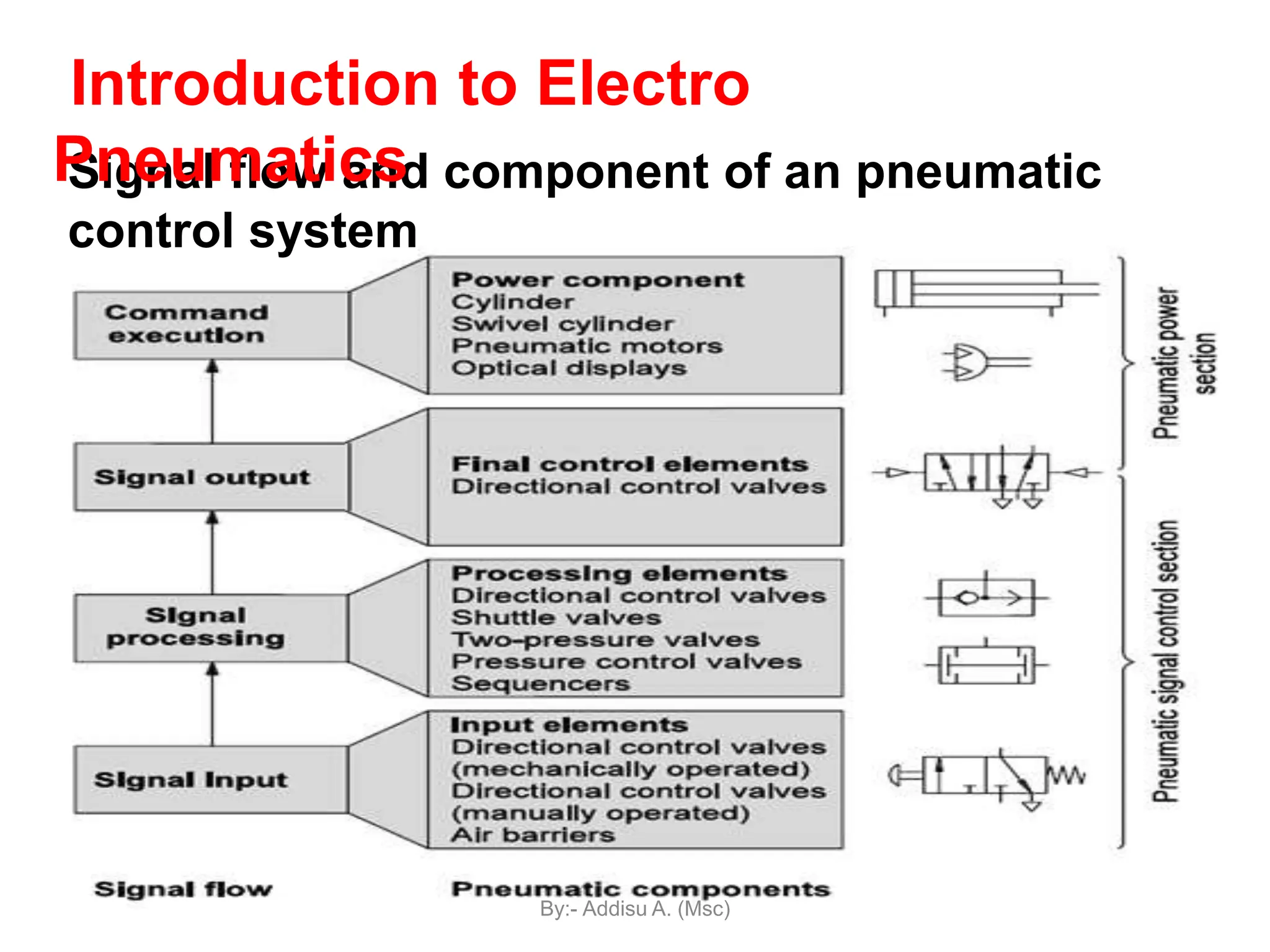
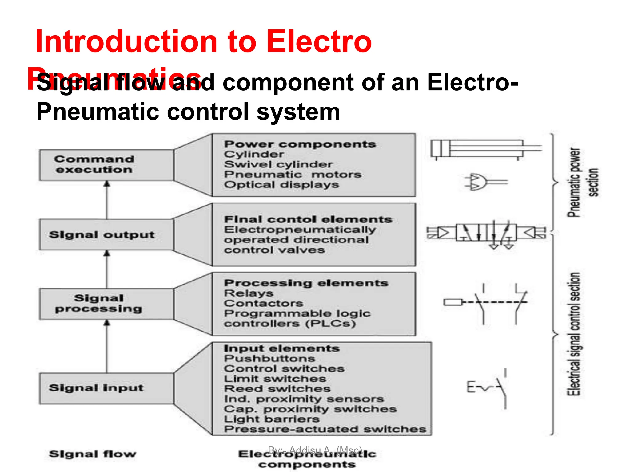
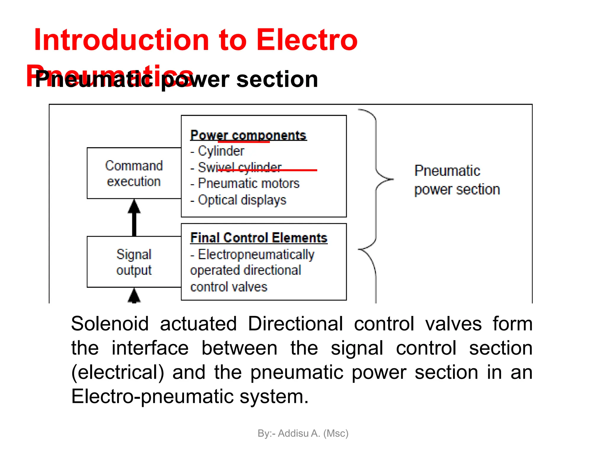
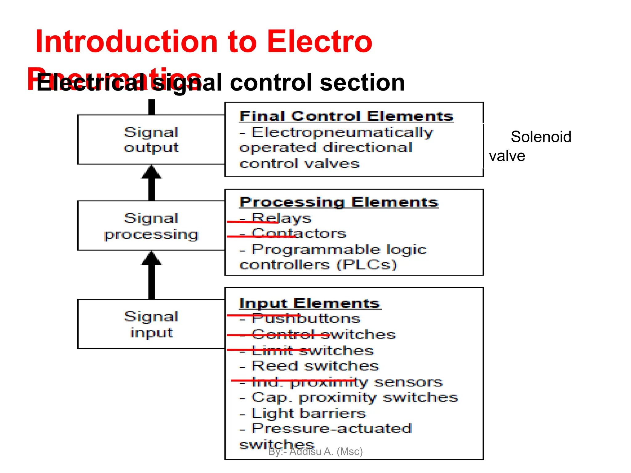
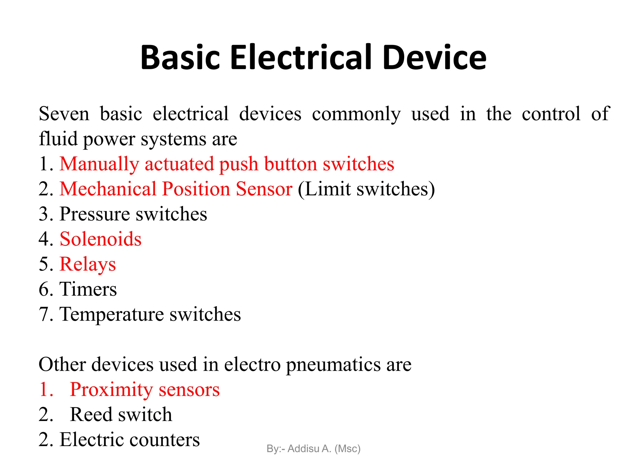
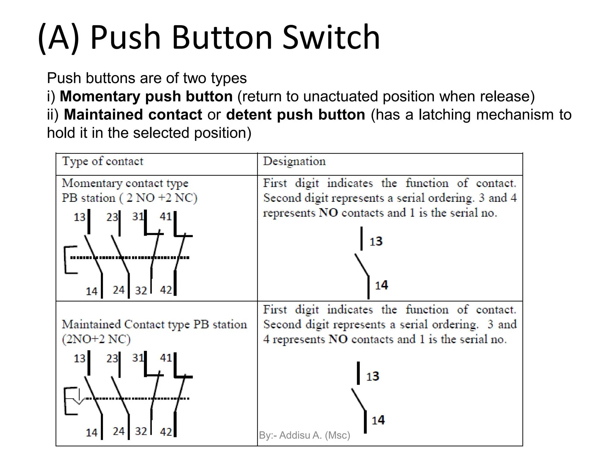
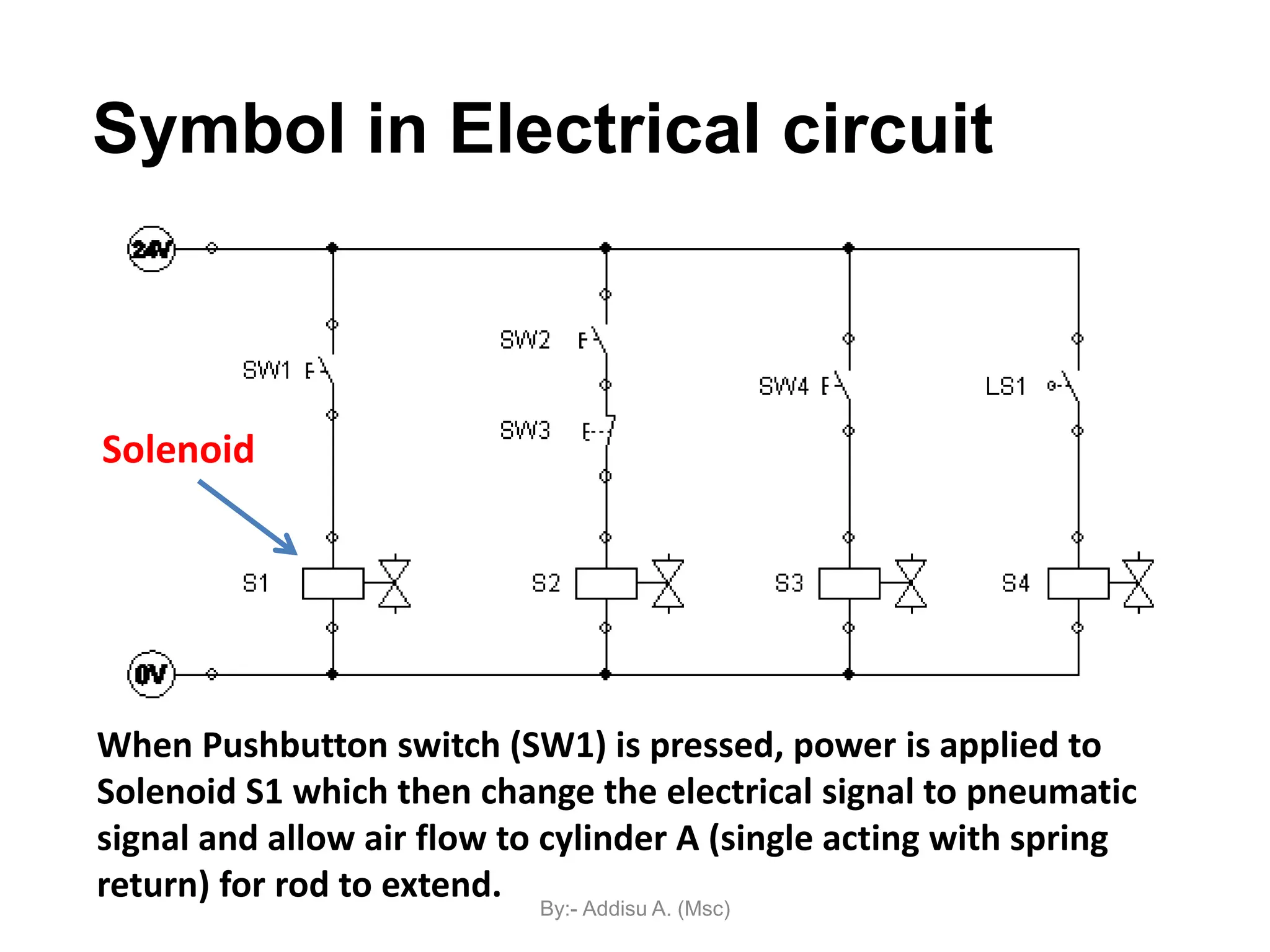
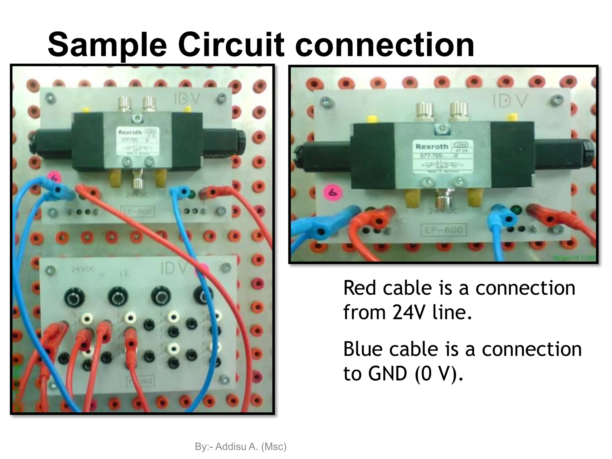
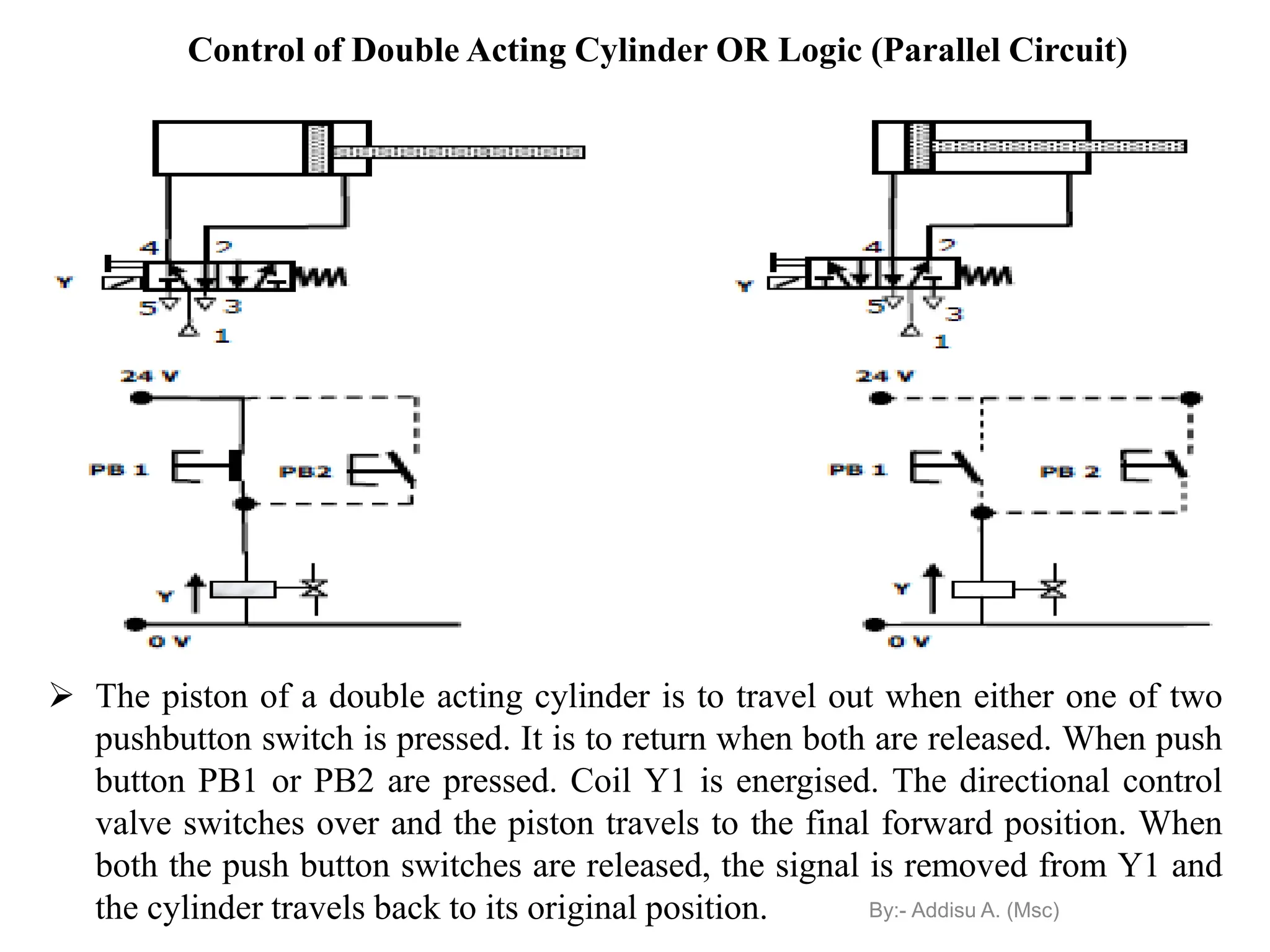
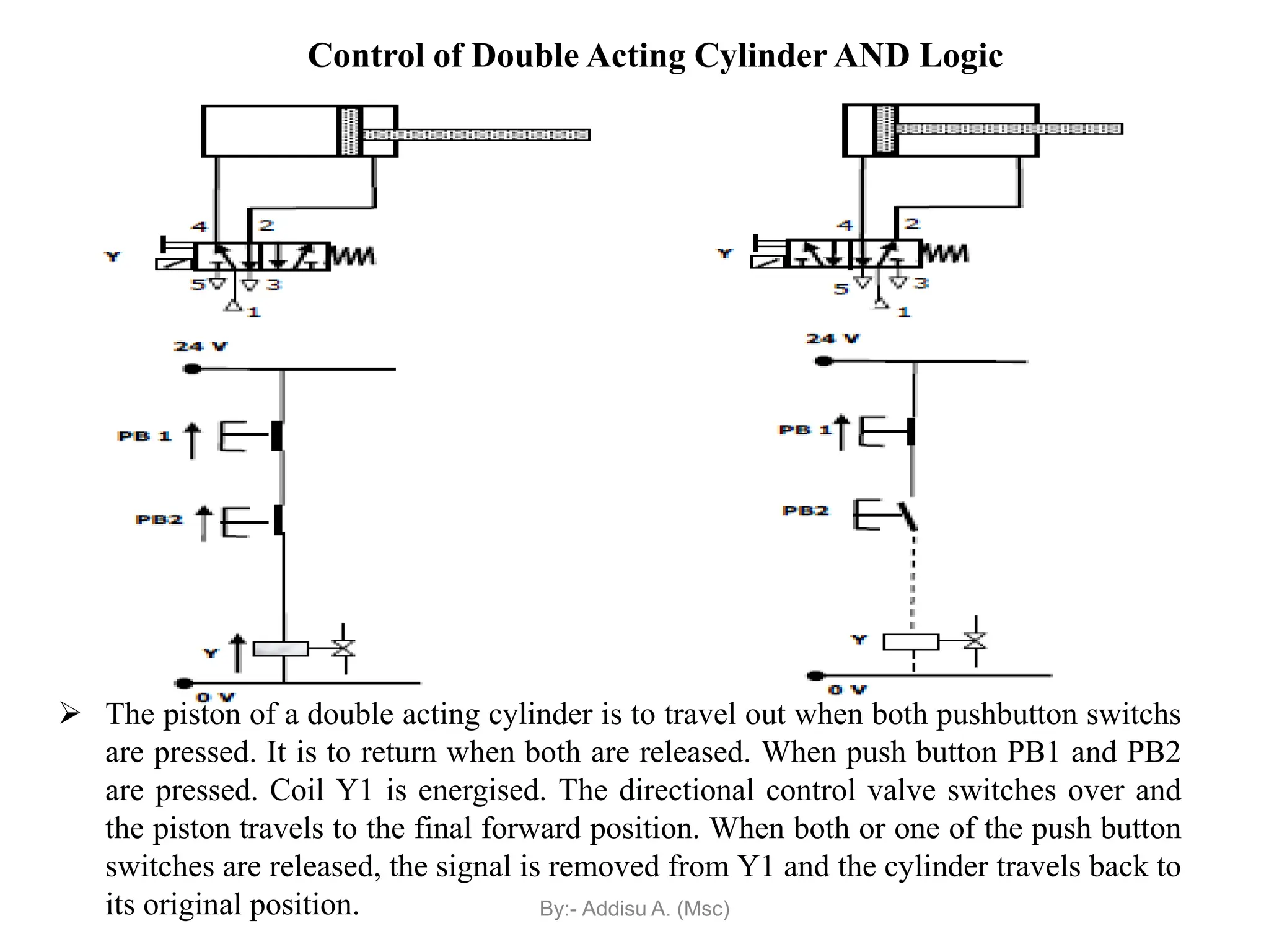
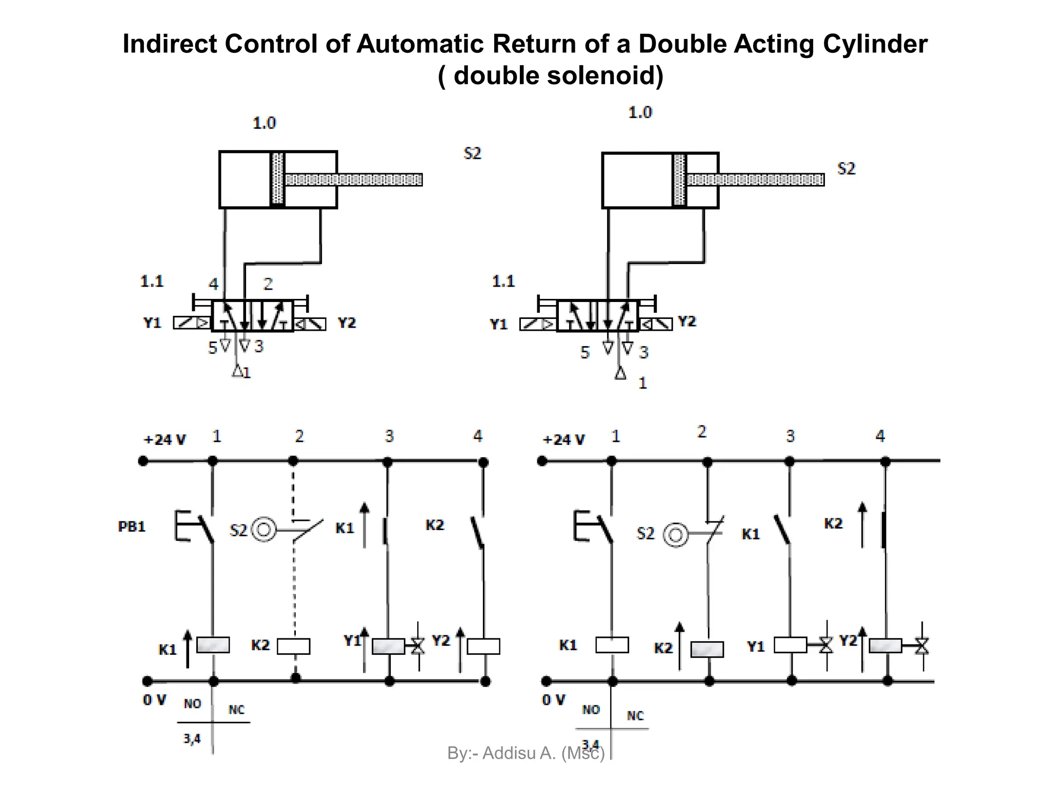
Introduction to Electro-pneumatics
By:- Addisu A. (Msc)
Introduction to Electro
Pneumatics
Definition :
 Electro-pneumatic term is defined from the words of
electro which means electrical and pneumatic which
means pressurized air.
 The electro-pneumatics equipments and system is an
integration of electrical and mechanical components
with compressed air source.
 Electro pneumatic is a pneumatic control system where
air pressure and direction of valve are controlled by an
electrical current.
Electro-Pneumatics
By:- Addisu A. (Msc)
Introduction to Electro
Pneumatics
• Pneumatics is a method to transfer energy from one point to another
using actuators which are driven by fluids under pressure (definition of
pneumatic).
Pneumatics restricts itself to gaseous fluids while hydraulics uses
liquids to transfer the energy.
 Pressure of the pneumatic system can be controlled by
 manually opening a valve,
 automatically by detecting its pressure,
 sending an electrical signal.
The control of pneumatic components by electrical impulses
(electrical signal) is known as electro-pneumatics.
Other Definition of Electro-Pneumatics
By:- Addisu A. (Msc)
Signal flow and component of an pneumatic
control system
Introduction to Electro
Pneumatics
By:- Addisu A. (Msc)
Introduction to Electro
Pneumatics
Signal flow and component of an Electro-
Pneumatic control system
By:- Addisu A. (Msc)
Introduction to Electro
Pneumatics
Pneumatic power section
Solenoid actuated Directional control valves form
the interface between the signal control section
(electrical) and the pneumatic power section in an
Electro-pneumatic system.
By:- Addisu A. (Msc)
Introduction to Electro
Pneumatics
Electrical signal control section
Solenoid
valve
By:- Addisu A. (Msc)
Introduction to Electro
Pneumatics
1. Lesser wear-off parts. Lesser installation jobs.
i.e., Electrical control valve, Electrical switches
2. Replace tube in pneumatic system to electrical wire in
electro-pneumatic
3. Less parts are used  Reduce working space.
4. Sensor and Controller (such as PLC) can be included in
the system
Advantages of using Electro-Pneumatics
Push Button
E-260
Electrical signal
input (switch
panel)
By:- Addisu A. (Msc)
Seven basic electrical devices commonly used in the control of
fluid power systems are
1. Manually actuated push button switches
2. Mechanical Position Sensor (Limit switches)
3. Pressure switches
4. Solenoids
5. Relays
6. Timers
7. Temperature switches
Other devices used in electro pneumatics are
1. Proximity sensors
2. Reed switch
2. Electric counters
Basic Electrical Device
By:- Addisu A. (Msc)
(A) Push Button Switch
Push buttons are of two types
i) Momentary push button (return to unactuated position when release)
ii) Maintained contact or detent push button (has a latching mechanism to
hold it in the selected position)
By:- Addisu A. (Msc)
Push Button Switch
By:- Addisu A. (Msc)
Example :
Normally Open (N.O) and Normally Close (N.C)
In pneumatic circuit :
For example : 3/2-way Push button (valve)
Normally Open Normally Close
In electrical circuit :
For example : Push button switch
Normally Open Normally Close
By:- Addisu A. (Msc)
(B)Mechanical Position sensor (limit
switch)
(Pneumatic)
3/2-way N.C valve with roller (Limit switch)
(Electro-Pneumatic)
Mechanical Position sensor (Limit switch)
By:- Addisu A. (Msc)
Limit Switch
• Any switch that is actuated due to the position of a fluid power
component (usually a piston rod or hydraulic motor shaft or the
position of load) is termed as limit switch.
• There are two types classification of Limit switches depending upon method of
actuations of contacts
a) Lever actuated contacts
b) Spring loaded contacts
• In lever type limit switches, the contacts are operated slowly. In spring type limit
switches, the contacts are operated rapidly. By:- Addisu A. (Msc)
 Proximity sensor contain a transistor which conducts and
switches (trigger ON) when something comes near to the
sensors.
 Some of the proximity sensor only work with steel
material components - Inductive proximity sensor
(C) Proximity sensor
By:- Addisu A. (Msc)
Question :
1. Name the switch type used for START and STOP button.
2. What is the different between A1 and A2 in Electrical circuit?
Proximity sensor – Symbol and Sample Circuit
Proximity Sensor
By:- Addisu A. (Msc)
 Relay is an electrically actuated switch, contains a coil and a
contactor switch or multiple contactors.
 When power is applied to relay coil, the core magnetizes,
drawing the contact assembly in.
 This will change the state of all the contacts in the relay (i.e.,
N.O contact becomes closed or N.C contact becomes open).
 Relay uses small amount of power to control switching
(advantage). The voltage applied to the coil doesn’t have to be
the same as that in control circuit.
 Relay is used to allow low voltage control systems to switch
large current/ high voltage
(D) Processing element - Relay
By:- Addisu A. (Msc)
Sample circuit
Coil
When Toggle switch 1S3 is pressed, power is supplied to Relay
(K1) coil which result to the all contactors in relay change their
state (open  close or close  open). Solenoid valve 1Y1
activate to ON
E-140
Contactor
By:- Addisu A. (Msc)
N.O and N.C wire / cable connection
Normally Close (N.C)
Example : Pin 21  22
Normally Open (N.O)
Example : Pin 41  44
By:- Addisu A. (Msc)
Animation (Relay OFF)
By:- Addisu A. (Msc)
Animation (Relay ON)
By:- Addisu A. (Msc)
More about Relays
 Relay has a few functions as a safety device:
1. The high voltage output (i.e. 240V) can be switched ON
through a contactor using relay with low voltage (i.e.
24V) supplied to a coil.
2. The high current output can be switched ON through a
contactor using relay with low current supplied to a coil.
3. Functioned as Safety control circuit for emergency
power cut-off (EMERGENCY START and STOP button)
to the whole circuit.
Use in automation process  Switching more than one
outputs simultaneously using relay with a coil and multiple
contactors.
To control ON and OFF of various outputs sequences using
several Relay.
By:- Addisu A. (Msc)
 Solenoid valve is an electro-mechanical device that built-in
with a coil (solenoid) and a pneumatic Directional control
valve.
 Directional control valve (DCV) solenoid operated use
electrical signals to control pneumatic valves.
 They are used to start, to stop and/or to change the
direction of air flow.
 There are 2 types operated of directional control valve
using solenoid:
1. Directly operated valve
2. Pilot operated valve
(E) Solenoid DCV
By:- Addisu A. (Msc)
1. Directly operated valve
 Flow is releases to the consuming device via armature of the
solenoid.
 In order to obtain a sufficient cross section of opening, a
comparably large armature is required. This consequently requires
a powerful return spring and the solenoid to generate a high force.
It is therefore of a large design with high power consumption.
2. Pilot operated valve
 The valve piston is moved via an air duct from pressure port1.This
only requires a Low flow so that a comparatively small armature
with minimal actuating force can be used. A minimum supply
pressure is required in order to actuate the piston against the spring
force. Solenoid can be configured in a small design and the power
consumption and heat emission is thus reduced.
By:- Addisu A. (Msc)
3/2 DCV single solenoid operated with spring
return
 The cross sectional view of 3/2 way single solenoid valve in the normal
and actuated positions are shown in Figure. In the normal position, port
1 is blocked and port 2 is connected to port 3 via back slot (details
shown in the circle) When the rated voltage is applied to coil, armature
is pulled towards the centre of the coil and in the process the armatures
is lifted away from the valve seat. The compressed air now flows from
port 1 to port 2, and ports 3 is blocked. When the voltage to the coil is
removed, the valve returns to the normal position.
By:- Addisu A. (Msc)
5/2 DCV single pilot operated single solenoid
with spring return
 The cross section view of 5/2 way single solenoid in the normal and
actuated positions are shown in Figure. In normal position, port 1 is
connected to port 2, port 4 is connected to port 5, and port 3 is blocked.
 When the rated voltage is applied to coil 14, the valve is actuated through
an internal pilot valve. In actuated position, port 1 is connected to port 4 ,
port 2 is connected to port 3, and port 5 is blocked. The valve returns to
the normal position when the voltage to the armature coil is removed.
By:- Addisu A. (Msc)
5/2 DCV double pilot operated double
solenoid
 The cross section view of 5/2 way double solenoid in the normal and actuated
positions are shown in the Figure when the rated voltage is applied to coil 14,
the valve is actuated to a one switch in position with port 1 connected to port
4, port 2 connected to port 3, and port 5 blocked. When the rated voltage is
applied to the coil 12, the valve is actuated to the other switching position
with port 1 connected to port 2, port 4 connected to port 5 and port 3 blocked.
By:- Addisu A. (Msc)
3/2 DCV single solenoid with manual
override with spring return
3/2 DCV single pilot operated single
solenoid with manual override with spring
return
5/2 DCV single solenoid with single
manual override with spring return
5/2 DCV double solenoid with double
manual override with spring return
5/2 DCV double pilot operated double
solenoid with double manual override
The symbols for the various solenoid/pilot actuated valves
are given in below
By:- Addisu A. (Msc)
5/2-DCV Single pilot operated
single solenoid with spring
return
3/2-DCV Single pilot operated
single solenoid with spring
return
Solenoid DCV
5/2-DCV double pilot operated
double solenoid
By:- Addisu A. (Msc)
Sample circuit
Pneumatic Power Component --- cylinder
Final Control element --- Solenoid valve
By:- Addisu A. (Msc)
Symbol in Electrical circuit
When Pushbutton switch (SW1) is pressed, power is applied to
Solenoid S1 which then change the electrical signal to pneumatic
signal and allow air flow to cylinder A (single acting with spring
return) for rod to extend.
Solenoid
By:- Addisu A. (Msc)
Sample Circuit connection
Red cable is a connection
from 24V line.
Blue cable is a connection
to GND (0 V).
By:- Addisu A. (Msc)
Supply / Power component
In Electro-Pneumatic system, the supply or power
source component is divided into two, based on the
system component.
1. Pneumatic - Compressor
2. Electrical -AC / DC power supply
Symbol for 24V DC
IEC Standard JIC Standard
By:- Addisu A. (Msc)
 Direct control is the control of an electro-pneumatic valve without using
intermediate components such as a relay, a contactor or an industrial computer
(PLC). The valve is connected directly to electric switch as shown in Fig. below
Direct control in electro-pneumatics
Advantages of direct control
•Simple and easy
•Less wiring
•Cheap.
Disadvantages of direct control
•Remote control is not possible
•Switching more than one valve at a
time is not possible
•Latching is not possible
•Design improvement is not flexible.
By:- Addisu A. (Msc)
Indirect control in electro pneumatics
 Indirect control is the control of an electro-pneumatic valve using
intermediate components such as relays, contactors or programmable
logic controllers (PLC).
Advantages of indirect control systems
•Remote control is possible
•Switching more than one valve at a time is possible
•Latching is possible.
•Flexible design improvement and development.
•Incorporating logic operating conditions (OR, AND
conditions)
Disadvantages of indirect control
•Complicated
•More wiring
•More cost involved
By:- Addisu A. (Msc)
Direct Control of Single Acting Cylinder
By:- Addisu A. (Msc)
Cont..
• Forward stroke: The circuit is closed when push button
PB closes.
• A magnetic field is produced in the coil Y. The armature in
the coil opens the passage for the compressed air.
• The compressed air flows from 1 to 2 of the 3/2 DCV to
cylinder, which travels to the final forward position.
• Return stroke: When the push button PB is released, the
circuit is interrupted.
• The magnetic field at coil Y collapses, the 3/2 way valve
switches back to its original position as shown in Figure .
• The compressed air in the cylinder then exhausts through
port 3 of the DCV and the cylinder travel to the final rear
position.
By:- Addisu A. (Msc)
Indirect Control of single acting cylinder
By:- Addisu A. (Msc)
Cont…
 Forward stroke: The circuit is closed when push button PB
closes. Closing of Push button PB energises a relay K1. The coil Y
is energised via normally open contact K1 (indirect energising).
A magnetic field is produced in armature of the coil Y opens the
passage for the compressed air. The compressed air flows from 1
to 2 of the 3/2 DCV to cylinder, which travels to the final forward
position.
• Return stroke: When the push button PB is released, the circuit is
interrupted. Opening of Push button PB de-energises a relay K1. The
magnetic field at coil Y is collapses due to the opening of contact K1 the
3/2 way valve switches back to its original position as shown in Figure.
The compressed air in the cylinder then exhausts through port 3 of the
DCV and the cylinder travel to the final rear position.
By:- Addisu A. (Msc)
Direct Control of Double Acting Cylinder
By:- Addisu A. (Msc)
Cont…
• Forward stroke: The double acting cylinder is controlled
by 5/2 way valve.
• When the pushbutton PB is pressed, coil Y is energised
and the directional control valve is activated by
compressed air via pilot control.
• The piston travels to the final forward position.
• Return stroke: When the push button PB is released, the
circuit is interrupted.
• The magnetic field at coil Y collapses, the return spring of
5/2 becomes active and the 5/2 way valve switches back to
its original position as shown in Figure . The compressed
air in the cylinder then exhausts through port 5 of the 5/2
DCV and the cylinder travel to the final rear position.
By:- Addisu A. (Msc)
Indirect Control of double acting cylinder
(using 5/2 way, single solenoid)
By:- Addisu A. (Msc)
Cont..
 Forward stroke: The circuit is closed when push button PB
closes. Closing of Push button PB energises a relay K1. The
coil Y is energised via normally open contact K1 (indirect
energising).
A magnetic field is produced in armature of the coil Y opens the
passage for the compressed air through internal pilot. The
compressed air flows from 1 to 4 of the 5/2 DCV to cylinder,
which travels to the final forward position.
• Return stroke: When the push button PB is released, the
circuit is interrupted. Opening of Push button PB de-energises
a relay K1. The magnetic field at coil Y is collapses due to the
opening of contact K1 the 5/2 way valve switches back to its
original position as shown in Figure 1.30. The compressed air
in the cylinder then exhausts through port 5 of the DCV and
the cylinder travel to the final rear position. By:- Addisu A. (Msc)
Indirect Control of double acting cylinder (using 5/2 way, double solenoid)
By:- Addisu A. (Msc)
Cont…
• Forward stroke: when push button PB1 is pressed, coil Y1 is
energised and 5/2 way directional control valve changes over. The
piston travels out and remains in the final forward position until a
signal is applied to coil Y2. The 5/2 directional control valve will
remain in the last position because it is double solenoid valve and has
no return spring.
• Return stroke: When the push button PB1 is released and PB2 is
pressed. Opening of Push button PB1 de-energises a relay K1. The
magnetic field at coil Y1 is collapses due to the opening of contact K1.
Closing of PB2 energises Y2 and the piston returns to its original
position as a result of changeover of the 5/2 way valve. The 5/2 way
directional control valve will not switch over if there is an active
opposing signal. For example, if Y1 is switched on and a signal is
given to Y2, there will be no reaction as there would be an opposing
signal
By:- Addisu A. (Msc)
Control of Double Acting Cylinder OR Logic (Parallel Circuit)
 The piston of a double acting cylinder is to travel out when either one of two
pushbutton switch is pressed. It is to return when both are released. When push
button PB1 or PB2 are pressed. Coil Y1 is energised. The directional control
valve switches over and the piston travels to the final forward position. When
both the push button switches are released, the signal is removed from Y1 and
the cylinder travels back to its original position. By:- Addisu A. (Msc)
 The piston of a double acting cylinder is to travel out when both pushbutton switchs
are pressed. It is to return when both are released. When push button PB1 and PB2
are pressed. Coil Y1 is energised. The directional control valve switches over and
the piston travels to the final forward position. When both or one of the push button
switches are released, the signal is removed from Y1 and the cylinder travels back to
its original position.
Control of Double Acting Cylinder AND Logic
By:- Addisu A. (Msc)
Indirect Control of Automatic Return of a Double Acting Cylinder
( double solenoid)
By:- Addisu A. (Msc)
Oscillating motion of a double acting cylinder (Forward )
By:- Addisu A. (Msc)
Oscillating motion of a double acting cylinder (Return )
By:- Addisu A. (Msc)

an introduction to electro pneumatic and

  • 1.
  • 2.
    Introduction to Electro Pneumatics Definition:  Electro-pneumatic term is defined from the words of electro which means electrical and pneumatic which means pressurized air.  The electro-pneumatics equipments and system is an integration of electrical and mechanical components with compressed air source.  Electro pneumatic is a pneumatic control system where air pressure and direction of valve are controlled by an electrical current. Electro-Pneumatics By:- Addisu A. (Msc)
  • 3.
    Introduction to Electro Pneumatics •Pneumatics is a method to transfer energy from one point to another using actuators which are driven by fluids under pressure (definition of pneumatic). Pneumatics restricts itself to gaseous fluids while hydraulics uses liquids to transfer the energy.  Pressure of the pneumatic system can be controlled by  manually opening a valve,  automatically by detecting its pressure,  sending an electrical signal. The control of pneumatic components by electrical impulses (electrical signal) is known as electro-pneumatics. Other Definition of Electro-Pneumatics By:- Addisu A. (Msc)
  • 4.
    Signal flow andcomponent of an pneumatic control system Introduction to Electro Pneumatics By:- Addisu A. (Msc)
  • 5.
    Introduction to Electro Pneumatics Signalflow and component of an Electro- Pneumatic control system By:- Addisu A. (Msc)
  • 6.
    Introduction to Electro Pneumatics Pneumaticpower section Solenoid actuated Directional control valves form the interface between the signal control section (electrical) and the pneumatic power section in an Electro-pneumatic system. By:- Addisu A. (Msc)
  • 7.
    Introduction to Electro Pneumatics Electricalsignal control section Solenoid valve By:- Addisu A. (Msc)
  • 8.
    Introduction to Electro Pneumatics 1.Lesser wear-off parts. Lesser installation jobs. i.e., Electrical control valve, Electrical switches 2. Replace tube in pneumatic system to electrical wire in electro-pneumatic 3. Less parts are used  Reduce working space. 4. Sensor and Controller (such as PLC) can be included in the system Advantages of using Electro-Pneumatics Push Button E-260 Electrical signal input (switch panel) By:- Addisu A. (Msc)
  • 9.
    Seven basic electricaldevices commonly used in the control of fluid power systems are 1. Manually actuated push button switches 2. Mechanical Position Sensor (Limit switches) 3. Pressure switches 4. Solenoids 5. Relays 6. Timers 7. Temperature switches Other devices used in electro pneumatics are 1. Proximity sensors 2. Reed switch 2. Electric counters Basic Electrical Device By:- Addisu A. (Msc)
  • 10.
    (A) Push ButtonSwitch Push buttons are of two types i) Momentary push button (return to unactuated position when release) ii) Maintained contact or detent push button (has a latching mechanism to hold it in the selected position) By:- Addisu A. (Msc)
  • 11.
    Push Button Switch By:-Addisu A. (Msc)
  • 12.
    Example : Normally Open(N.O) and Normally Close (N.C) In pneumatic circuit : For example : 3/2-way Push button (valve) Normally Open Normally Close In electrical circuit : For example : Push button switch Normally Open Normally Close By:- Addisu A. (Msc)
  • 13.
    (B)Mechanical Position sensor(limit switch) (Pneumatic) 3/2-way N.C valve with roller (Limit switch) (Electro-Pneumatic) Mechanical Position sensor (Limit switch) By:- Addisu A. (Msc)
  • 14.
    Limit Switch • Anyswitch that is actuated due to the position of a fluid power component (usually a piston rod or hydraulic motor shaft or the position of load) is termed as limit switch. • There are two types classification of Limit switches depending upon method of actuations of contacts a) Lever actuated contacts b) Spring loaded contacts • In lever type limit switches, the contacts are operated slowly. In spring type limit switches, the contacts are operated rapidly. By:- Addisu A. (Msc)
  • 15.
     Proximity sensorcontain a transistor which conducts and switches (trigger ON) when something comes near to the sensors.  Some of the proximity sensor only work with steel material components - Inductive proximity sensor (C) Proximity sensor By:- Addisu A. (Msc)
  • 16.
    Question : 1. Namethe switch type used for START and STOP button. 2. What is the different between A1 and A2 in Electrical circuit? Proximity sensor – Symbol and Sample Circuit Proximity Sensor By:- Addisu A. (Msc)
  • 17.
     Relay isan electrically actuated switch, contains a coil and a contactor switch or multiple contactors.  When power is applied to relay coil, the core magnetizes, drawing the contact assembly in.  This will change the state of all the contacts in the relay (i.e., N.O contact becomes closed or N.C contact becomes open).  Relay uses small amount of power to control switching (advantage). The voltage applied to the coil doesn’t have to be the same as that in control circuit.  Relay is used to allow low voltage control systems to switch large current/ high voltage (D) Processing element - Relay By:- Addisu A. (Msc)
  • 18.
    Sample circuit Coil When Toggleswitch 1S3 is pressed, power is supplied to Relay (K1) coil which result to the all contactors in relay change their state (open  close or close  open). Solenoid valve 1Y1 activate to ON E-140 Contactor By:- Addisu A. (Msc)
  • 19.
    N.O and N.Cwire / cable connection Normally Close (N.C) Example : Pin 21  22 Normally Open (N.O) Example : Pin 41  44 By:- Addisu A. (Msc)
  • 20.
  • 21.
  • 22.
    More about Relays Relay has a few functions as a safety device: 1. The high voltage output (i.e. 240V) can be switched ON through a contactor using relay with low voltage (i.e. 24V) supplied to a coil. 2. The high current output can be switched ON through a contactor using relay with low current supplied to a coil. 3. Functioned as Safety control circuit for emergency power cut-off (EMERGENCY START and STOP button) to the whole circuit. Use in automation process  Switching more than one outputs simultaneously using relay with a coil and multiple contactors. To control ON and OFF of various outputs sequences using several Relay. By:- Addisu A. (Msc)
  • 23.
     Solenoid valveis an electro-mechanical device that built-in with a coil (solenoid) and a pneumatic Directional control valve.  Directional control valve (DCV) solenoid operated use electrical signals to control pneumatic valves.  They are used to start, to stop and/or to change the direction of air flow.  There are 2 types operated of directional control valve using solenoid: 1. Directly operated valve 2. Pilot operated valve (E) Solenoid DCV By:- Addisu A. (Msc)
  • 24.
    1. Directly operatedvalve  Flow is releases to the consuming device via armature of the solenoid.  In order to obtain a sufficient cross section of opening, a comparably large armature is required. This consequently requires a powerful return spring and the solenoid to generate a high force. It is therefore of a large design with high power consumption. 2. Pilot operated valve  The valve piston is moved via an air duct from pressure port1.This only requires a Low flow so that a comparatively small armature with minimal actuating force can be used. A minimum supply pressure is required in order to actuate the piston against the spring force. Solenoid can be configured in a small design and the power consumption and heat emission is thus reduced. By:- Addisu A. (Msc)
  • 25.
    3/2 DCV singlesolenoid operated with spring return  The cross sectional view of 3/2 way single solenoid valve in the normal and actuated positions are shown in Figure. In the normal position, port 1 is blocked and port 2 is connected to port 3 via back slot (details shown in the circle) When the rated voltage is applied to coil, armature is pulled towards the centre of the coil and in the process the armatures is lifted away from the valve seat. The compressed air now flows from port 1 to port 2, and ports 3 is blocked. When the voltage to the coil is removed, the valve returns to the normal position. By:- Addisu A. (Msc)
  • 26.
    5/2 DCV singlepilot operated single solenoid with spring return  The cross section view of 5/2 way single solenoid in the normal and actuated positions are shown in Figure. In normal position, port 1 is connected to port 2, port 4 is connected to port 5, and port 3 is blocked.  When the rated voltage is applied to coil 14, the valve is actuated through an internal pilot valve. In actuated position, port 1 is connected to port 4 , port 2 is connected to port 3, and port 5 is blocked. The valve returns to the normal position when the voltage to the armature coil is removed. By:- Addisu A. (Msc)
  • 27.
    5/2 DCV doublepilot operated double solenoid  The cross section view of 5/2 way double solenoid in the normal and actuated positions are shown in the Figure when the rated voltage is applied to coil 14, the valve is actuated to a one switch in position with port 1 connected to port 4, port 2 connected to port 3, and port 5 blocked. When the rated voltage is applied to the coil 12, the valve is actuated to the other switching position with port 1 connected to port 2, port 4 connected to port 5 and port 3 blocked. By:- Addisu A. (Msc)
  • 28.
    3/2 DCV singlesolenoid with manual override with spring return 3/2 DCV single pilot operated single solenoid with manual override with spring return 5/2 DCV single solenoid with single manual override with spring return 5/2 DCV double solenoid with double manual override with spring return 5/2 DCV double pilot operated double solenoid with double manual override The symbols for the various solenoid/pilot actuated valves are given in below By:- Addisu A. (Msc)
  • 29.
    5/2-DCV Single pilotoperated single solenoid with spring return 3/2-DCV Single pilot operated single solenoid with spring return Solenoid DCV 5/2-DCV double pilot operated double solenoid By:- Addisu A. (Msc)
  • 30.
    Sample circuit Pneumatic PowerComponent --- cylinder Final Control element --- Solenoid valve By:- Addisu A. (Msc)
  • 31.
    Symbol in Electricalcircuit When Pushbutton switch (SW1) is pressed, power is applied to Solenoid S1 which then change the electrical signal to pneumatic signal and allow air flow to cylinder A (single acting with spring return) for rod to extend. Solenoid By:- Addisu A. (Msc)
  • 32.
    Sample Circuit connection Redcable is a connection from 24V line. Blue cable is a connection to GND (0 V). By:- Addisu A. (Msc)
  • 33.
    Supply / Powercomponent In Electro-Pneumatic system, the supply or power source component is divided into two, based on the system component. 1. Pneumatic - Compressor 2. Electrical -AC / DC power supply Symbol for 24V DC IEC Standard JIC Standard By:- Addisu A. (Msc)
  • 34.
     Direct controlis the control of an electro-pneumatic valve without using intermediate components such as a relay, a contactor or an industrial computer (PLC). The valve is connected directly to electric switch as shown in Fig. below Direct control in electro-pneumatics Advantages of direct control •Simple and easy •Less wiring •Cheap. Disadvantages of direct control •Remote control is not possible •Switching more than one valve at a time is not possible •Latching is not possible •Design improvement is not flexible. By:- Addisu A. (Msc)
  • 35.
    Indirect control inelectro pneumatics  Indirect control is the control of an electro-pneumatic valve using intermediate components such as relays, contactors or programmable logic controllers (PLC). Advantages of indirect control systems •Remote control is possible •Switching more than one valve at a time is possible •Latching is possible. •Flexible design improvement and development. •Incorporating logic operating conditions (OR, AND conditions) Disadvantages of indirect control •Complicated •More wiring •More cost involved By:- Addisu A. (Msc)
  • 36.
    Direct Control ofSingle Acting Cylinder By:- Addisu A. (Msc)
  • 37.
    Cont.. • Forward stroke:The circuit is closed when push button PB closes. • A magnetic field is produced in the coil Y. The armature in the coil opens the passage for the compressed air. • The compressed air flows from 1 to 2 of the 3/2 DCV to cylinder, which travels to the final forward position. • Return stroke: When the push button PB is released, the circuit is interrupted. • The magnetic field at coil Y collapses, the 3/2 way valve switches back to its original position as shown in Figure . • The compressed air in the cylinder then exhausts through port 3 of the DCV and the cylinder travel to the final rear position. By:- Addisu A. (Msc)
  • 38.
    Indirect Control ofsingle acting cylinder By:- Addisu A. (Msc)
  • 39.
    Cont…  Forward stroke:The circuit is closed when push button PB closes. Closing of Push button PB energises a relay K1. The coil Y is energised via normally open contact K1 (indirect energising). A magnetic field is produced in armature of the coil Y opens the passage for the compressed air. The compressed air flows from 1 to 2 of the 3/2 DCV to cylinder, which travels to the final forward position. • Return stroke: When the push button PB is released, the circuit is interrupted. Opening of Push button PB de-energises a relay K1. The magnetic field at coil Y is collapses due to the opening of contact K1 the 3/2 way valve switches back to its original position as shown in Figure. The compressed air in the cylinder then exhausts through port 3 of the DCV and the cylinder travel to the final rear position. By:- Addisu A. (Msc)
  • 40.
    Direct Control ofDouble Acting Cylinder By:- Addisu A. (Msc)
  • 41.
    Cont… • Forward stroke:The double acting cylinder is controlled by 5/2 way valve. • When the pushbutton PB is pressed, coil Y is energised and the directional control valve is activated by compressed air via pilot control. • The piston travels to the final forward position. • Return stroke: When the push button PB is released, the circuit is interrupted. • The magnetic field at coil Y collapses, the return spring of 5/2 becomes active and the 5/2 way valve switches back to its original position as shown in Figure . The compressed air in the cylinder then exhausts through port 5 of the 5/2 DCV and the cylinder travel to the final rear position. By:- Addisu A. (Msc)
  • 42.
    Indirect Control ofdouble acting cylinder (using 5/2 way, single solenoid) By:- Addisu A. (Msc)
  • 43.
    Cont..  Forward stroke:The circuit is closed when push button PB closes. Closing of Push button PB energises a relay K1. The coil Y is energised via normally open contact K1 (indirect energising). A magnetic field is produced in armature of the coil Y opens the passage for the compressed air through internal pilot. The compressed air flows from 1 to 4 of the 5/2 DCV to cylinder, which travels to the final forward position. • Return stroke: When the push button PB is released, the circuit is interrupted. Opening of Push button PB de-energises a relay K1. The magnetic field at coil Y is collapses due to the opening of contact K1 the 5/2 way valve switches back to its original position as shown in Figure 1.30. The compressed air in the cylinder then exhausts through port 5 of the DCV and the cylinder travel to the final rear position. By:- Addisu A. (Msc)
  • 44.
    Indirect Control ofdouble acting cylinder (using 5/2 way, double solenoid) By:- Addisu A. (Msc)
  • 45.
    Cont… • Forward stroke:when push button PB1 is pressed, coil Y1 is energised and 5/2 way directional control valve changes over. The piston travels out and remains in the final forward position until a signal is applied to coil Y2. The 5/2 directional control valve will remain in the last position because it is double solenoid valve and has no return spring. • Return stroke: When the push button PB1 is released and PB2 is pressed. Opening of Push button PB1 de-energises a relay K1. The magnetic field at coil Y1 is collapses due to the opening of contact K1. Closing of PB2 energises Y2 and the piston returns to its original position as a result of changeover of the 5/2 way valve. The 5/2 way directional control valve will not switch over if there is an active opposing signal. For example, if Y1 is switched on and a signal is given to Y2, there will be no reaction as there would be an opposing signal By:- Addisu A. (Msc)
  • 46.
    Control of DoubleActing Cylinder OR Logic (Parallel Circuit)  The piston of a double acting cylinder is to travel out when either one of two pushbutton switch is pressed. It is to return when both are released. When push button PB1 or PB2 are pressed. Coil Y1 is energised. The directional control valve switches over and the piston travels to the final forward position. When both the push button switches are released, the signal is removed from Y1 and the cylinder travels back to its original position. By:- Addisu A. (Msc)
  • 47.
     The pistonof a double acting cylinder is to travel out when both pushbutton switchs are pressed. It is to return when both are released. When push button PB1 and PB2 are pressed. Coil Y1 is energised. The directional control valve switches over and the piston travels to the final forward position. When both or one of the push button switches are released, the signal is removed from Y1 and the cylinder travels back to its original position. Control of Double Acting Cylinder AND Logic By:- Addisu A. (Msc)
  • 48.
    Indirect Control ofAutomatic Return of a Double Acting Cylinder ( double solenoid) By:- Addisu A. (Msc)
  • 49.
    Oscillating motion ofa double acting cylinder (Forward ) By:- Addisu A. (Msc)
  • 50.
    Oscillating motion ofa double acting cylinder (Return ) By:- Addisu A. (Msc)