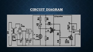
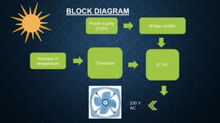
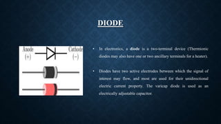
AUTOMATIC FAN CONTROLLER BASED ON
ROOM TEMPERATURE
Prepared by
P NIKHIL KUMAR REDDY
ECE
CIRCUIT DIAGRAM
KIT
IC 741Thermistor
Bridge rectifier
Increase in
temperature
Power supply
(230V)
230 V
AC
BLOCK DIAGRAM
OBJECTIVES
• BRIDGE RECTFIER
• IC 7812
• THERMISTER
• RESISTORS & VARIABLE RESISTOR
• CAPACITOR
• IC 741
• TRANSISTOR
• DIODE (2222N)
• RELAY(12V) DPDT
INTRODUCTION
• This automatic fan controller is used to monitor the temperature of the load without any human interruption by
using temperature depends upon thermistor. Generally fan speed is controlled manually. it is done by normal
regulator circuit which is controlled outside manually. In this project if the temperature increase a certain limit.
Then a fan is automatically switched on to bring the temperature to normal state.
• The automatic fan controller circuit uses a thermistor along with an operational amplifier is used for monitoring
the input voltages. The thermistor temperature sensor is used to detect the temperature. If the temperature
exceeds the predefined limit, then the thermistor will give a signal to operational amplifier to activate the lamp
using a relay to retain the temperature at that value.
BRIDGE RECTIFIER
• A Bridge rectifier is an arrangements of four or
more Diodes in a bridge circuit configuration.
which provides same output polarity.
• It is used for converting an alternating current
(AC) Input into a direct current (DC) as output.
IC 7812
• The ic 7812 is also called as voltage regulator has 3 pin
Input
Ground
Output
A voltage regulator is a electronic device. This is designed
It can operate both in AC&DC
THERMISTER
• A thermistor is a type of resistor whose resistance dependent on
temperature . The word is a portmanteau of thermal and resistor.
thermistors are widely used as current limiters.
• Thermistors are differs from resistance temperature detectors.
In this thermistors generally a ceramic (or) polymer material is used.
There are 2 types of thermistors :-
I. NTC – Negative temperature co-efficient
II. PTC - Positive temperature co-efficient
VARIABLE RESISTOR
• A Variable resistor consists of a track which provides the resistance
path. Two terminals of a device is connected to both
the end of a track. The third terminal is connected to a WIPER
that decides the motion of a track. The motion of track helps the
increase or decrease the resistance.
• A potentiometer has 3 terminals in this two terminals are fixed
and one terminal is movable. Variable resistor is also called as
potentiometer. Potentiometers are operated by rotating shafts.
Potentiometers are commonly used to control electrical devices.
CAPACITOR
• An electrical device consisting of two conducting plates
separated by an electrical insulator (the dielectric ), designed
to hold an electric charge.
• Charge builds up when a voltage is applied across the plates,
creating an electric field between them.
• The standard unit of capacitance is the farad. Symbol is “F”.
Three prefixes (multipliers) are used, µ (micro), n (nano) and p
(pico):
 µ means 10-6 (millionth), so 1000000µF = 1F
 n means 10-9 (thousand-millionth), so 1000nF = 1µF
 p means 10-12 (million-millionth), so 1000pF = 1nF
TRANSISTOR
• A transistor is a semiconductor device used as amplifier and
switch electronic signals and electrical power.
• A transistor is a basic electrical component that alters the flow of
electrical current.
• If we now join together two individual signal diodes back-to-
back, this will give us two PN-junctions connected together in
series that share a common P or N terminal. The fusion of these
two diodes produces a three layer, two junction, three terminal
device forming the basis of a Bipolar Junction Transistor, or BJT.
DIODE
• In electronics, a diode is a two-terminal device (Thermionic
diodes may also have one or two ancillary terminals for a heater).
• Diodes have two active electrodes between which the signal of
interest may flow, and most are used for their unidirectional
electric current property. The varicap diode is used as an
electrically adjustable capacitor.
RELAY (12V) DPDT
• An electrically operated switch, for example a 9V battery circuit
connected to the coil can switch a 230V AC mains circuit.
NO = Normally Open, COM = Common, NC = Normally Closed.
ADVANTAGES & DISADVANTAGES
• Quick cooling.
• More moisture removable.
• Lower fan noise and quieter operations.
• Good for night time. When cooling loads are low and humidity is high.
ADVANTAGSE:-
DISADVANTAGES:-
• Thermistor is the heart of the circuit , if thermistor is damaged the whole circuit
well be damaged .
• Speed control is independent of individual preference.
APPLICATIONS
• Applicable to the protection of the power circuits of conversion power supply.
• Applicable for switching power supply, UPS power supply, electric heaters, incandescent
lamps and other lights.
• It is also applicable for A.C’s, kitchen exhausters, ceiling fans.
Automatic fan controller based on room temperature

Automatic fan controller based on room temperature

  • 1.
    AUTOMATIC FAN CONTROLLERBASED ON ROOM TEMPERATURE Prepared by P NIKHIL KUMAR REDDY ECE
  • 2.
  • 3.
  • 4.
    IC 741Thermistor Bridge rectifier Increasein temperature Power supply (230V) 230 V AC BLOCK DIAGRAM
  • 5.
    OBJECTIVES • BRIDGE RECTFIER •IC 7812 • THERMISTER • RESISTORS & VARIABLE RESISTOR • CAPACITOR • IC 741 • TRANSISTOR • DIODE (2222N) • RELAY(12V) DPDT
  • 6.
    INTRODUCTION • This automaticfan controller is used to monitor the temperature of the load without any human interruption by using temperature depends upon thermistor. Generally fan speed is controlled manually. it is done by normal regulator circuit which is controlled outside manually. In this project if the temperature increase a certain limit. Then a fan is automatically switched on to bring the temperature to normal state. • The automatic fan controller circuit uses a thermistor along with an operational amplifier is used for monitoring the input voltages. The thermistor temperature sensor is used to detect the temperature. If the temperature exceeds the predefined limit, then the thermistor will give a signal to operational amplifier to activate the lamp using a relay to retain the temperature at that value.
  • 7.
    BRIDGE RECTIFIER • ABridge rectifier is an arrangements of four or more Diodes in a bridge circuit configuration. which provides same output polarity. • It is used for converting an alternating current (AC) Input into a direct current (DC) as output.
  • 8.
    IC 7812 • Theic 7812 is also called as voltage regulator has 3 pin Input Ground Output A voltage regulator is a electronic device. This is designed It can operate both in AC&DC
  • 9.
    THERMISTER • A thermistoris a type of resistor whose resistance dependent on temperature . The word is a portmanteau of thermal and resistor. thermistors are widely used as current limiters. • Thermistors are differs from resistance temperature detectors. In this thermistors generally a ceramic (or) polymer material is used. There are 2 types of thermistors :- I. NTC – Negative temperature co-efficient II. PTC - Positive temperature co-efficient
  • 10.
    VARIABLE RESISTOR • AVariable resistor consists of a track which provides the resistance path. Two terminals of a device is connected to both the end of a track. The third terminal is connected to a WIPER that decides the motion of a track. The motion of track helps the increase or decrease the resistance. • A potentiometer has 3 terminals in this two terminals are fixed and one terminal is movable. Variable resistor is also called as potentiometer. Potentiometers are operated by rotating shafts. Potentiometers are commonly used to control electrical devices.
  • 11.
    CAPACITOR • An electricaldevice consisting of two conducting plates separated by an electrical insulator (the dielectric ), designed to hold an electric charge. • Charge builds up when a voltage is applied across the plates, creating an electric field between them. • The standard unit of capacitance is the farad. Symbol is “F”. Three prefixes (multipliers) are used, µ (micro), n (nano) and p (pico):  µ means 10-6 (millionth), so 1000000µF = 1F  n means 10-9 (thousand-millionth), so 1000nF = 1µF  p means 10-12 (million-millionth), so 1000pF = 1nF
  • 12.
    TRANSISTOR • A transistoris a semiconductor device used as amplifier and switch electronic signals and electrical power. • A transistor is a basic electrical component that alters the flow of electrical current. • If we now join together two individual signal diodes back-to- back, this will give us two PN-junctions connected together in series that share a common P or N terminal. The fusion of these two diodes produces a three layer, two junction, three terminal device forming the basis of a Bipolar Junction Transistor, or BJT.
  • 13.
    DIODE • In electronics,a diode is a two-terminal device (Thermionic diodes may also have one or two ancillary terminals for a heater). • Diodes have two active electrodes between which the signal of interest may flow, and most are used for their unidirectional electric current property. The varicap diode is used as an electrically adjustable capacitor.
  • 14.
    RELAY (12V) DPDT •An electrically operated switch, for example a 9V battery circuit connected to the coil can switch a 230V AC mains circuit. NO = Normally Open, COM = Common, NC = Normally Closed.
  • 15.
    ADVANTAGES & DISADVANTAGES •Quick cooling. • More moisture removable. • Lower fan noise and quieter operations. • Good for night time. When cooling loads are low and humidity is high. ADVANTAGSE:- DISADVANTAGES:- • Thermistor is the heart of the circuit , if thermistor is damaged the whole circuit well be damaged . • Speed control is independent of individual preference.
  • 16.
    APPLICATIONS • Applicable tothe protection of the power circuits of conversion power supply. • Applicable for switching power supply, UPS power supply, electric heaters, incandescent lamps and other lights. • It is also applicable for A.C’s, kitchen exhausters, ceiling fans.