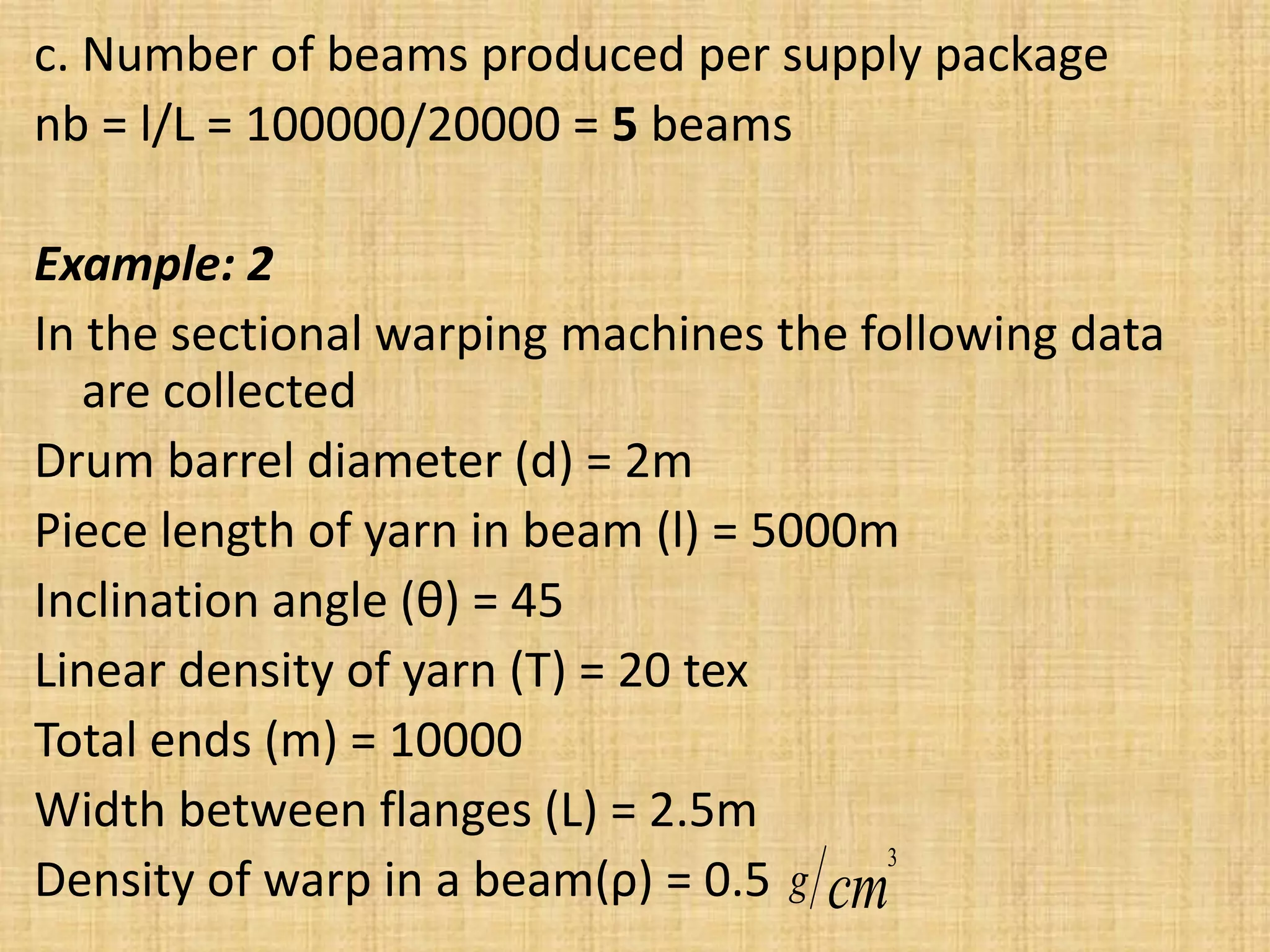
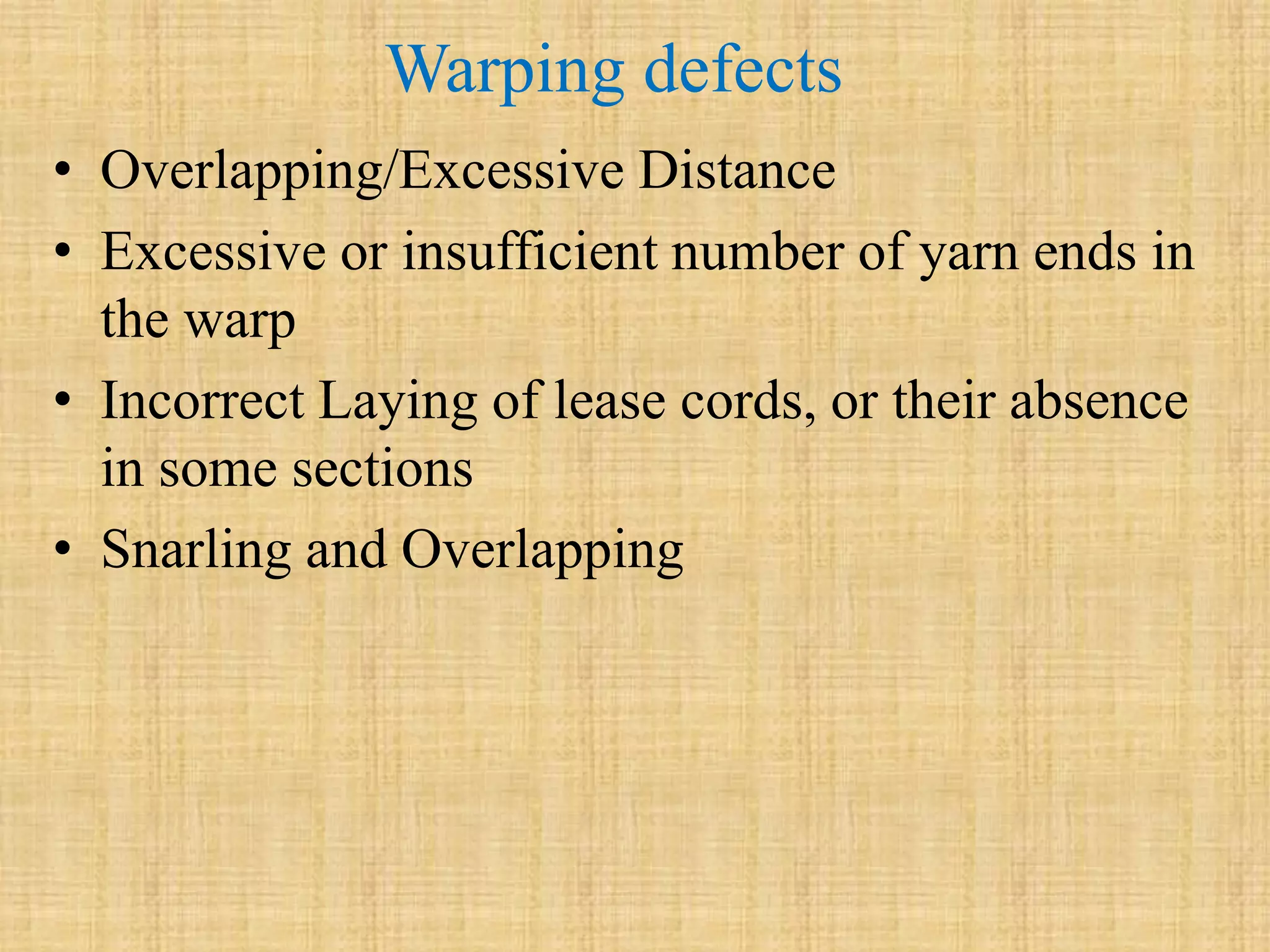
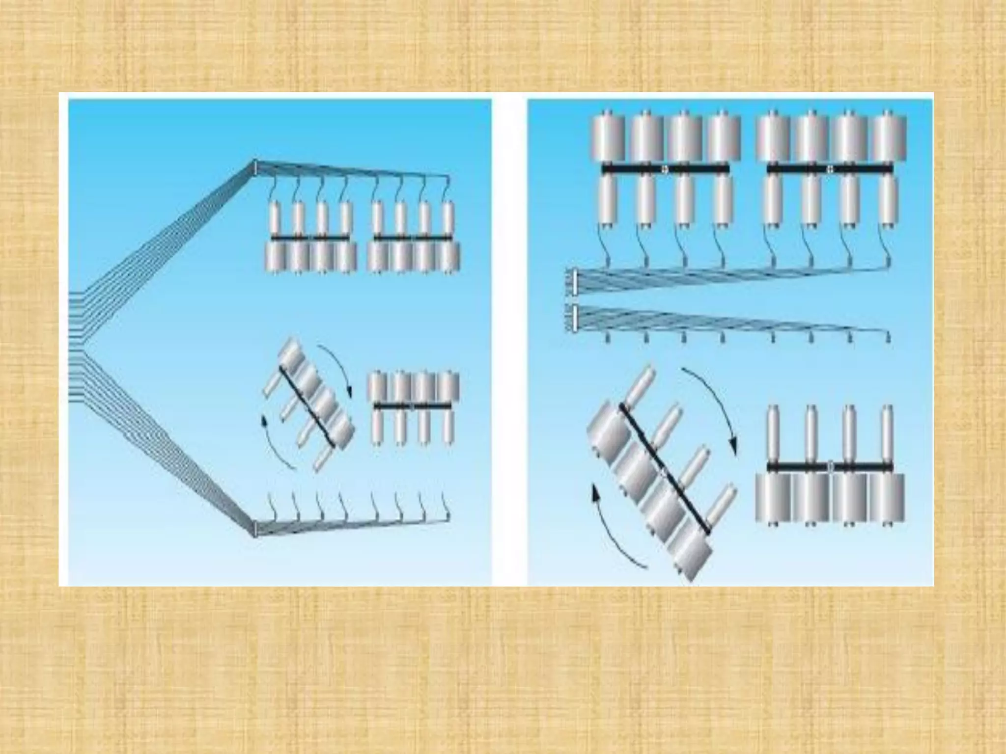
Warping is the process of combining yarns into a sheet known as a warped beam. The main objective is to produce a uniform warped beam from multiple cones or bobbins. A warping creel holds the yarn packages and maintains uniform tension. Common creel types include V-shaped, truck, magazine, duplicative, and automatic creels. Warping defects can occur if there are issues like overlapping ends, incorrect yarn counts or laying of lease cords. Productivity calculations consider factors like yarn speed, beam length, number of ends, and machine efficiency.


![Calculation of warping machines productivity
The productivity of warping machines can be
expressed by the amount of yarn wound on a
warpers beam or a weavers beam per given time.
The productivity of a beam warping machine can
be:
P =V × t × T × m × Ԑ × 10−6 [Kg/hr]
Where:
V= Average speed of warping machine (m/min)
T= Rated time(min)
T= Linear density of yarn (tex)
M= number of ends wound simultaneously on to beam
Ԑ= machine efficiency](https://image.slidesharecdn.com/warping-210127074055/75/Warping-process-21-2048.jpg)


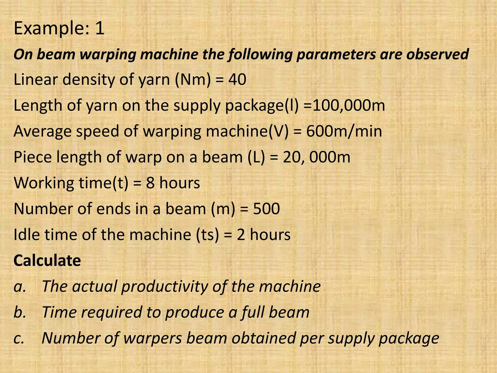
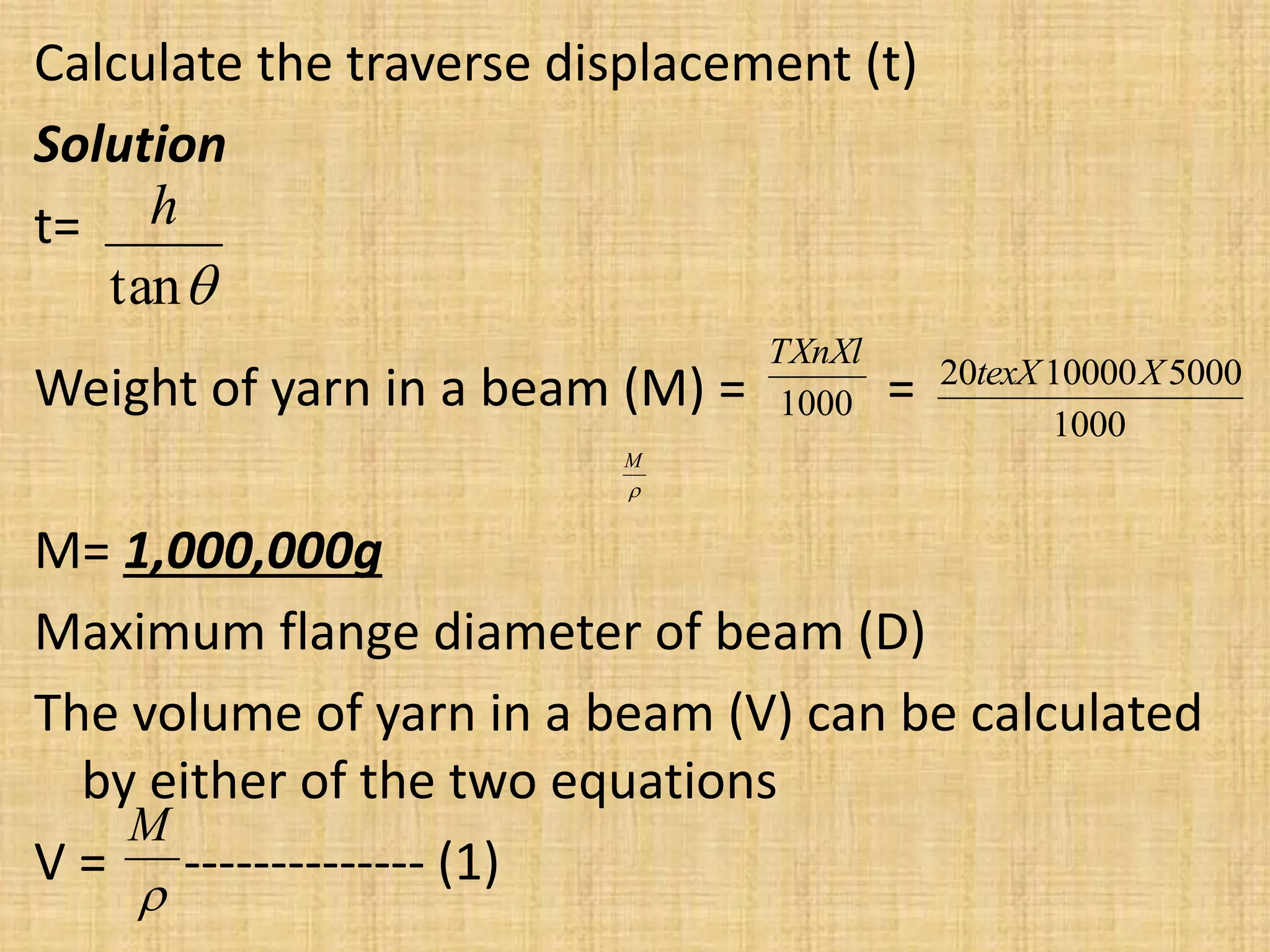
![solution
a. P =V(m/min) × t(min) × T(tex) × m × Ԑ × 10−6
[Kg/shift]
Tex = 1000/Nm = 1000/40 = 25
t = 8 X60min = 480min
Ԑ = t-ts/t X100= 8-2/8X100 = 6/8X100 = 75%
So, P =600m/min× 480min × 25 × 500 × 75%× 10−6 [Kg/shift]
P= 2700 Kg/shift
b. Time required for a full beam
tb = L/V = 20,000m/600m/min = 33.3min](https://image.slidesharecdn.com/warping-210127074055/75/Warping-process-25-2048.jpg)