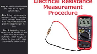
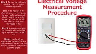
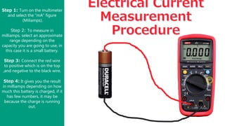
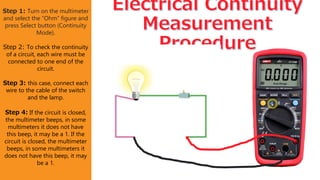
2. The Hold/Light Button
Pressing the button turn on the screen
light.
Range Button
This Will help you “click throug”
different meter rangers.
Minivolts for DC
Shift: Milivolts for AC.
DC Voltage
AC Voltage
Shift: VFC (voltage/frequency
converter).
Current Jack
Measures currents with clam
attachments, or with a red lead.
mAμA
Measures currents milliampere until
microampere conection.
Frecuency Button
Measure in Hz.
SELECT/V.F.C
Changes the values to blue shift.
Shift Capacitace
This measures your capacitance.
Hz%
Tell you your circuit’s frecuency.
RELΔ
Stores input values.
μA DC
Measures in microampere.
Shift: measures in AC.
mA DC
Measures in miliampere.
Shift: measures in AC.
A DC
Measures in ampers.
Shift: measures in AC.
NCV
AutoSensing feature enables the meter
to recognize the input.
Red Jack
It have a variety of symbols of
measurement above it.Common Jack
It is compatible with all measurements.
Ohms
Helps you to get the acurrate
resistance. Shift: Continuity.
MAX/MIN Button
Stores input values.
3. UNI-T's UT139B is a True RMS Auto Range Digital Multimeter with 4000 display count and 1kHz
bandwidth, featuring VFC, NCV, Max/Min/Rel measurements.
The meter can measure AC/DC Voltage and Current, variable frequency voltage (V.F.C.),
resistance, diode, circuit on-off, capacitance, frequency ratio.
SPECIFICATION:
DC Voltage: 40mV/400mV/4V/40V/400V/600V
- accuracy: ±(0.5%+2)
AC Voltage: 40mV/400mV/4V/40V/400V/600V
- accuracy: ±(0.8%+3)
DC Current:400uA/4000uA/40mA/400mA/4A/10A
- accuracy: +/- (0.8%+2)
AC Current:400uA/4000uA/40mA/400mA/4A/10A
- accuracy: +/- (1%+3)
Resistance: 400Ω/4kΩ/40kΩ400kΩ/4MΩ40MΩ
- accuracy: +/- (0.8%+2)
Capacitance: 9.999nF/99.99nF/999.9nF/99.99uF
/999.9uF/9.999mF/99.99mF
- accuracy: +- (4%+5)
Frequency: 10Hz - 10MHz
- accuracy: +- (0.1%+4)
FUNCTIONS:
Autorange
True RMS
Bandwidth 45Hz-1kHz
Diode test
NCV
Auto Power Off
Continuity buzzer
Low Battery Indication
Data hold
Relative mod
Display Backlight
Input Protection 600Vrms
4. Step 1: Turn on the multimeter
and select the “Ω” figure
(Ohm button).
Step 2: You can measure the
resistance of a component in a
circuit, I chose a resistor, but
make sure you have adequate
protection depending on the
case.
Step 3: Depending on the
variation of the resistance, it will
show you a result on the
multimeter screen, this you can
change the range to give you a
more specific measurement.
5. Step 1: Turn on the multimeter
and select the “V~” figure
(Alternating Current).
Step 2: To measure in the
alternating current you have to
be very careful and aware of
what is being done, as in light
contact, you can ask for help
from someone with prior
knowledge of this.
Step 3: Connect the red wire
to phase which is the smallest
input, and neutral to the black
wire.
Step 4: It will mark an
approximate voltage of 120v or
220v depending on the case and
thus you will ensure that you did
everything right.
6. Step 1: Turn on the multimeter
and select the “mA” figure
(Miliamps).
Step 2: To measure in
milliamps, select an approximate
range depending on the
capacity you are going to use, in
this case it is a small battery.
Step 3: Connect the red wire
to positive which is on the top
,and negative to the black wire.
Step 4: It gives you the result
in milliamps depending on how
much this battery is charged, if it
has few numbers, it may be
because the charge is running
out.
7. Step 1: Turn on the multimeter
and select the “Ohm” figure and
press Select button (Continuity
Mode).
Step 2: To check the continuity
of a circuit, each wire must be
connected to one end of the
circuit.
Step 3: this case, connect each
wire to the cable of the switch
and the lamp.
Step 4: If the circuit is closed,
the multimeter beeps, in some
multimeters it does not have
this beep, it may be a 1. If the
circuit is closed, the multimeter
beeps, in some multimeters it
does not have this beep, it may
be a 1.
8. MULTIMETER SAFETY PRECAUTIONS
As with other meters, the incorrect use of a multimeter could cause injury or damage.
The following safety precautions are the MINIMUM for using a multimeter.
• Deenergize and discharge the circuit completely before connecting or disconnecting a
multimeter.
• Never apply power to the circuit while measuring resistance with a multimeter.
• Connect the multimeter in series with the circuit for current measurements, and in parallel for
voltage measurements.
• Be certain the multimeter is switched to ac before attempting to measure ac circuits.
• Observe proper dc polarity when measuring dc.
• When you are finished with a multimeter, switch it to the OFF position, if available.
• If there is no OFF position, switch the multimeter to the highest ac voltage position.
• Always start with the highest voltage or current range.
• Select a final range that allows a reading near the middle of the scale.
• Adjust the "0 ohms" reading after changing resistance ranges and before making a resistance
measurement.
• Be certain to read ac measurements on the ac scale of a multimeter.
• Observe the general safety precautions for electrical and electronic devices.