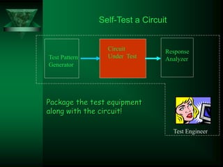
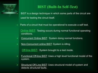
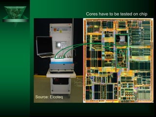
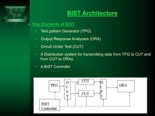
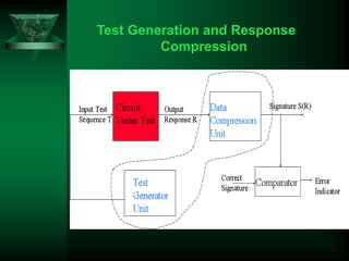
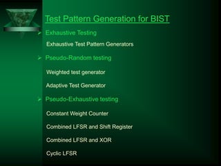
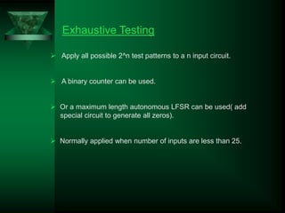
VLSI TESTING
Built-In Self-Test(BIST)
By
GSV.PRABHUJI
ROLLNO:13
OVERVIEW
 BIST (Built-In Self-Test)
 BIST Architecture
 BIST Advantages
 BIST Disadvantages & Applications
 Conclusion
Testing a Circuit
Circuit Under
Test
Test Pattern
Generator
Response
Analyzer
Test Equipment
• Pulse and Function generators
• Oscilloscope
• Logic Analyzers
• Computers
+
Test Engineer
Self-Test a Circuit
Circuit
Under Test
Test Pattern
Generator
Response
Analyzer
Test Engineer
Package the test equipment
along with the circuit!
BIST (Built-In Self-Test)
 BIST is a design technique in which some parts of the circuit are
used for testing the circuit itself.
 Parts of a circuit that must be operational to execute a self test.
Online BIST: Testing occurs during normal functional operating
conditions.
 Concurrent Online BIST: System doing normal functions.
 Non-Concurrent online BIST: System is idling.
Off-line BIST: System brought to a test mode.
 Functional Off-line BIST: Uses a high level functional model of the
system.
 Structural Off-Line BIST: Uses structural model of system and
detects structural faults.
Core 2
Core 3 Core 4 Core 5
Embedded Tester
Core 1
Test access
mechanism
BIST BIST
BIST
BIST
BIST
Test
Controller
Tester
Memory
Source: Elcoteq
Cores have to be tested on chip
BIST Architecture
 Key Elements of BIST
• Test pattern Generator (TPG)
• Output Response Analyzers (ORA)
• Circuit Under Test (CUT)
• A Distribution system for transmitting data from TPG to CUT and
from CUT to ORAs.
• A BIST Controller
Test Generation and Response
Compression
Test Pattern Generation for BIST
 Exhaustive Testing
Exhaustive Test Pattern Generators
 Pseudo-Random testing
Weighted test generator
Adaptive Test Generator
 Pseudo-Exhaustive testing
Constant Weight Counter
Combined LFSR and Shift Register
Combined LFSR and XOR
Cyclic LFSR
Exhaustive Testing
 Apply all possible 2^n test patterns to a n input circuit.
 A binary counter can be used.
 Or a maximum length autonomous LFSR can be used( add
special circuit to generate all zeros).
 Normally applied when number of inputs are less than 25.
Pseudorandom Testing
 Patterns are generated deterministically but have characteristics
of random patterns.
 Pseudo-random patterns without replacement can be generated
using autonomous LFSRs.
 Test length can be chosen to achieve the desired fault coverage.
This can be determined using fault simulation.
Weighted Test Generation
 Generate Test Patterns with the desired distribution of 1’s and 0’s.
 Such a generator can be constructed using a LFSR and a
combinational circuit.
 Different parts of the circuit may require different distribution of 0’s
and 1’s.
Adaptive Test Generation
 Also employs weighted test pattern generation.
 Fault simulation is used to determine weights for various faults.
 Different distributions are used for different class of faults.
 A Test Pattern Generator (TPG) is designed to produce the
required distributions.
 Advantage: Small test lengths
 Disadvantage: Costly TPG hardware
Pseudo-exhaustive Testing
 Circuit is segmented & each segment is tested exhaustively, by
Logical Segmentation, Cone Segmentation, Sensitized path
segmentation, Physical Segmentation.
 Requires fewer tests but has the advantage of exhaustive testing.
 Segments the circuit into parts and each segment is exhaustively
tested.
Response Compression for BIST
General Aspects of Compression
 A simple hardware implementation.
 It should not slow down normal operations.
 Good Compression
• The signatures of good and faulty circuit should be different.
• Small size of signature, Signature size should be log of data
size.
 Response compression : A process to form a “signature” from
complete output responses.
 Signature : Compressed form of saved test results.
 Alias : Errorous output when faulty & fault-free sig. are the same.
To generate signatures for good circuit
 Applying the test to good part of the CUT.
 Simulating the CUT and making sure of having good signature.
 Fault Tolerant : Producing copies of CUT and conclude the correct
signature by finding the subset which generates the same signature.
 One’s count : The no. of times when 1 occurs in each output (counter).
 Transition count : The no. of transitions(0 =>1,1=>0) in the output
(XOR +counter).
 Parity checking : The parity of response string, 0 if even & 1 if odd
(XOR + D-FF).
 Syndrome checking : The normalized no. of 1’s in output string (k/2**n
when k is no. of minterms in an n input circuit), (All possible combination
tests).
 LFSR : Shift register that feed back bits through XOR functions.
• Used both for Pseudo-Random Binary Sequence (PRBS) generation
and for signature generation.
Advantages
 Reduced testing and maintenance cost
 Lower test generation cost
 Reduced storage / maintenance of test patterns
 Simpler and less expensive ATE
 Can test many units in parallel
 Shorter test application times
 Can test at functional system speed
Faults tested:
 Single stuck-at faults
 Delay faults
 Single stuck-at faults in BIST hardware
Disadvantages
 Silicon area overhead
 Access time
 Requires the use of extra pins
 Correctness is not assured
Applications
 Mission-critical sytems.
 self-diagnostic circuitry (consumer electronics).
CONCLUSION
Based upon the Test Generation and Response Compression of
BIST the following varitions will results.
Testing time  Memory cost 
Powerconsumption  Hardware cost 
Test quality 
QUESTION TIME
THANK U

VLSI TESTING.ppt

  • 1.
  • 2.
    OVERVIEW  BIST (Built-InSelf-Test)  BIST Architecture  BIST Advantages  BIST Disadvantages & Applications  Conclusion
  • 3.
    Testing a Circuit CircuitUnder Test Test Pattern Generator Response Analyzer Test Equipment • Pulse and Function generators • Oscilloscope • Logic Analyzers • Computers + Test Engineer
  • 4.
    Self-Test a Circuit Circuit UnderTest Test Pattern Generator Response Analyzer Test Engineer Package the test equipment along with the circuit!
  • 5.
    BIST (Built-In Self-Test) BIST is a design technique in which some parts of the circuit are used for testing the circuit itself.  Parts of a circuit that must be operational to execute a self test. Online BIST: Testing occurs during normal functional operating conditions.  Concurrent Online BIST: System doing normal functions.  Non-Concurrent online BIST: System is idling. Off-line BIST: System brought to a test mode.  Functional Off-line BIST: Uses a high level functional model of the system.  Structural Off-Line BIST: Uses structural model of system and detects structural faults.
  • 6.
    Core 2 Core 3Core 4 Core 5 Embedded Tester Core 1 Test access mechanism BIST BIST BIST BIST BIST Test Controller Tester Memory
  • 7.
    Source: Elcoteq Cores haveto be tested on chip
  • 8.
    BIST Architecture  KeyElements of BIST • Test pattern Generator (TPG) • Output Response Analyzers (ORA) • Circuit Under Test (CUT) • A Distribution system for transmitting data from TPG to CUT and from CUT to ORAs. • A BIST Controller
  • 9.
    Test Generation andResponse Compression
  • 10.
    Test Pattern Generationfor BIST  Exhaustive Testing Exhaustive Test Pattern Generators  Pseudo-Random testing Weighted test generator Adaptive Test Generator  Pseudo-Exhaustive testing Constant Weight Counter Combined LFSR and Shift Register Combined LFSR and XOR Cyclic LFSR
  • 11.
    Exhaustive Testing  Applyall possible 2^n test patterns to a n input circuit.  A binary counter can be used.  Or a maximum length autonomous LFSR can be used( add special circuit to generate all zeros).  Normally applied when number of inputs are less than 25.
  • 12.
    Pseudorandom Testing  Patternsare generated deterministically but have characteristics of random patterns.  Pseudo-random patterns without replacement can be generated using autonomous LFSRs.  Test length can be chosen to achieve the desired fault coverage. This can be determined using fault simulation.
  • 13.
    Weighted Test Generation Generate Test Patterns with the desired distribution of 1’s and 0’s.  Such a generator can be constructed using a LFSR and a combinational circuit.  Different parts of the circuit may require different distribution of 0’s and 1’s.
  • 14.
    Adaptive Test Generation Also employs weighted test pattern generation.  Fault simulation is used to determine weights for various faults.  Different distributions are used for different class of faults.  A Test Pattern Generator (TPG) is designed to produce the required distributions.  Advantage: Small test lengths  Disadvantage: Costly TPG hardware
  • 15.
    Pseudo-exhaustive Testing  Circuitis segmented & each segment is tested exhaustively, by Logical Segmentation, Cone Segmentation, Sensitized path segmentation, Physical Segmentation.  Requires fewer tests but has the advantage of exhaustive testing.  Segments the circuit into parts and each segment is exhaustively tested.
  • 16.
    Response Compression forBIST General Aspects of Compression  A simple hardware implementation.  It should not slow down normal operations.  Good Compression • The signatures of good and faulty circuit should be different. • Small size of signature, Signature size should be log of data size.
  • 17.
     Response compression: A process to form a “signature” from complete output responses.  Signature : Compressed form of saved test results.  Alias : Errorous output when faulty & fault-free sig. are the same. To generate signatures for good circuit  Applying the test to good part of the CUT.  Simulating the CUT and making sure of having good signature.
  • 18.
     Fault Tolerant: Producing copies of CUT and conclude the correct signature by finding the subset which generates the same signature.  One’s count : The no. of times when 1 occurs in each output (counter).  Transition count : The no. of transitions(0 =>1,1=>0) in the output (XOR +counter).  Parity checking : The parity of response string, 0 if even & 1 if odd (XOR + D-FF).  Syndrome checking : The normalized no. of 1’s in output string (k/2**n when k is no. of minterms in an n input circuit), (All possible combination tests).  LFSR : Shift register that feed back bits through XOR functions. • Used both for Pseudo-Random Binary Sequence (PRBS) generation and for signature generation.
  • 19.
    Advantages  Reduced testingand maintenance cost  Lower test generation cost  Reduced storage / maintenance of test patterns  Simpler and less expensive ATE  Can test many units in parallel  Shorter test application times  Can test at functional system speed Faults tested:  Single stuck-at faults  Delay faults  Single stuck-at faults in BIST hardware
  • 20.
    Disadvantages  Silicon areaoverhead  Access time  Requires the use of extra pins  Correctness is not assured Applications  Mission-critical sytems.  self-diagnostic circuitry (consumer electronics).
  • 21.
    CONCLUSION Based upon theTest Generation and Response Compression of BIST the following varitions will results. Testing time  Memory cost  Powerconsumption  Hardware cost  Test quality 
  • 22.
  • 23.