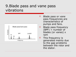
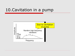
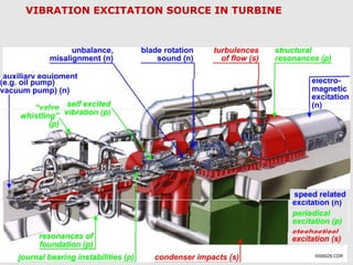
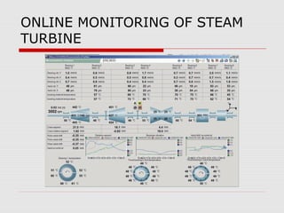
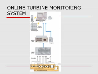
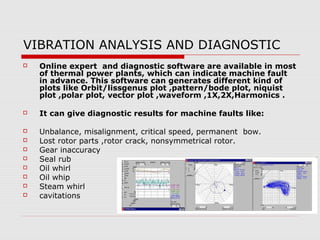
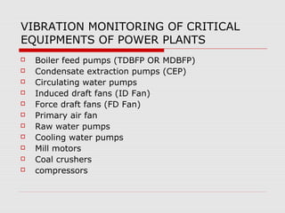
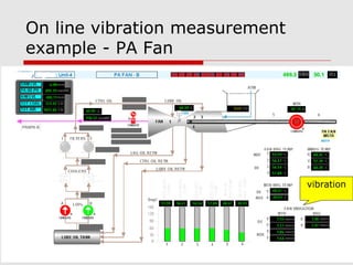
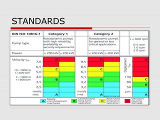
VIBRATION ANALYSIS AT
THERMAL POWER PLANTS
SHIVAJI CHOUDHURY
Objective
 To increase equipment protection;
 To improve safety for personnel;
 To improve maintenance procedures;
 To detect problems early;
 To avoid catastrophic failures;
 To extend equipment life;
 To enhance operations.
Vibration monitoring
 Vibration monitoring is the technology of
measuring vibration characteristics such as
amplitude, frequency, and velocity at
specific locations (for example, bearing
housings) to identify abnormal conditions
or faulty components in rotating machinery.
 Vibration problems can originate from
design, installation, set up, in-service wear,
or maintenance.
Vibration Analysis
(frequency domain)
 A great deal of vibration analysis is done in
the frequency domain because the various
sources of vibration can usually be isolated
by the frequencies at which they occur.
 A single channel analysed in the frequency
domain gives a great deal of information,
but often it is important to relate vibration
to a second channel as either a phase or
amplitude reference, or both.
VIBRATION ANALYSIS(FFT)
 The basic technique for converting a
broadband time trace to discrete frequencies,
or frequency bands, is by the application of
the Fourier transform (FT).
 This analysis can be realized with the help of
a computer and signal processing software,
by special devices (which are usually called a
Fourier analyser), or by hardware microchips
(DSPs).
 More commonly used in analysers now is a
more efficient mathematical routine, the fast
Fourier transform (FFT).
DEFECT DETECTED USING
VIBRATION ANALYSIS(FFT)
 1.Unbalance machine.
 2.Bent shaft.
 3.Components loose in rotor.
 4.Rotor rub.
 5.Journal bearing .
 6.Gears.
 7.Electrical problem.
 8.Bearing.
 9 blade pass and vane pass vibration.
 10.cavitation in pump.
1.UNBALANCE MACHINE
 Changes in balance
will give change in
the 1x vector.
 At fixed speed
vibration
amplitudes are
constants.
 Amplitude varies
proportional to the
square of speed.
2.BENT SHAFT
 Change of 1x is
most common ,if
rotor is bent near
coupling a higher
2x axial vibration is
frequently
observed
 At a fixed speed
the rotor vibration
values are
constant.
3.COMPONENTS LOOSENESS IN
ROTOR
 Vibration values
may be erratic and
inconsistent
between start-stop
cycle. Sometime
subhormonics
frequencies are
also observed.
4.ROTOR RUB
 Most commonly
1X,but also
multiples of 1X
,subsynchronous
frequencies and
natural
frequencies.
5.JOURNAL BEARING
 Vibration frequency-
1X,2X,3X.
 Changes in bearing
operating condition or
geometry can cause
changes in steady state
vibration at 1X and
higher harmonics or
cause subsynchronous
(oil or steam whirl) ,in
latter case the vibration
is usually unsteady and
can increase with time
,often rapidly.
5.1.Oil whirl( journal bearing)
 Its frequency has
been reported to be
anywhere from
approximately 42 to
almost 48 percent of
rpm.
 Simply view oil whirl
vibration frequency as
"slightly less than ½ x
rpm.
6.GEAR
 Detection requires
transducers with
high frequency
responses.
 For defect in one
tooth: 1x multiples.
 For worn teeth gear
mesh frequency with
sidebands and
multiples.
6.1.GEARS
7.ELECTRIC PROBLEMS
 Stiffness dissymmetry (e g axial winding
slot in generator/motor rotor): vibration
peaks when 2X stimulus is coincident with
rotor critical speed .compensating grooves
are used as large machine to minimize
stimulus.
 Thermal dissymmetry: can caused by
nonuniform rotor ventilation or shorted
electrical winding or nonuniform tightness
of parts ,cause rotor to bow with the same
vibration characteristic as unbalance.
7.1.ELECTRIC MOTOR
7.2.ELECTRIC MOTOR
8.BEARING
 Bearing misalignment :1X,2X,or high
harmonics. Parallel or angular bearing
misalignment is generally caused by
foundation movement .bearing
misalignment is not direct cause of
vibration excitation but changes the
dynamics characteristics of support system.
 Roller element bearing wear: wideband
acceleration at high frequency.
8.1.BEARING
9.Blade pass and vane pass
vibrations
 Blade pass or vane
pass frequencies are
characteristics of
pumps and fans.
 Blade pass frequency
(BPF) = number of
blades (or vanes) x
rpm
 This frequency is
generated mainly due
to the gap problems
between the rotor and
the stator.
10.Cavitation in a pump
Due to cavitation
in pump
Typical Vibration Components
Measured in Large Centrifugal Pumps
VIBRATION ANALYSIS AT THERMAL
POWER PLANT
 Vibration sensors have been routinely installed on
main turbines, generator and some large pumps to
monitor bearing vibration levels.
 Main Turbine is the heart of the power plant. Turbine
is the most critical part of the plant & it is mandatory
to use maximum protections as well as on line
measurements of different parameters to avoid any
unexpected failure/shutdown.
 Power plants have begun to use this technology as a
predictive maintenance tool for identifying incipient
failures in many types of rotating equipment such as
fans, pumps, and compressors.
Potential failure (P-F) curve
Vibration
monitoring
The curve shows that as a failure starts manifesting, the equipment
deteriorates to the point at which it can possibly be detected (P).
If the failure is not detected and corrected, it continues until a
failure occurs (F) and repair cost will increases .
VIBRATION EXCITATION SOURCE IN TURBINE
ONLINE MONITORING OF STEAM
TURBINE
ONLINE TURBINE MONITORING
SYSTEM
VIBRATION ANALYSIS AND DIAGNOSTIC
 Online expert and diagnostic software are available in most
of thermal power plants, which can indicate machine fault
in advance. This software can generates different kind of
plots like Orbit/lissgenus plot ,pattern/bode plot, niquist
plot ,polar plot, vector plot ,waveform ,1X,2X,Harmonics .
 It can give diagnostic results for machine faults like:
 Unbalance, misalignment, critical speed, permanent bow.
 Lost rotor parts ,rotor crack, nonsymmetrical rotor.
 Gear inaccuracy
 Seal rub
 Oil whirl
 Oil whip
 Steam whirl
 cavitations
VIBRATION MONITORING OF CRITICAL
EQUIPMENTS OF POWER PLANTS
 Boiler feed pumps (TDBFP OR MDBFP)
 Condensate extraction pumps (CEP)
 Circulating water pumps
 Induced draft fans (ID Fan)
 Force draft fans (FD Fan)
 Primary air fan
 Raw water pumps
 Cooling water pumps
 Mill motors
 Coal crushers
 compressors
On line vibration measurement
example - PA Fan
vibration
Vibration measurement monthly
schedule for critical equipments
S N Equipment 1ST
WEEK 2ND
WEEK 3RD
WEEK 4TH
WEEK
1 ID FANS Y
2 FD FANS Y
3 PA FANS Y Y
4 MILL GEAR BOX Y Y
5 SEAL AIR FANS Y Y
6 BFP Y
7 CEP Y
8 CW PUMPS Y
9 Other Pumps,
fans ,compressor
Y
STANDARDS
STANDARDS
THANKYOU

Vibration analysis at thermal power plants

  • 1.
    VIBRATION ANALYSIS AT THERMALPOWER PLANTS SHIVAJI CHOUDHURY
  • 2.
    Objective  To increaseequipment protection;  To improve safety for personnel;  To improve maintenance procedures;  To detect problems early;  To avoid catastrophic failures;  To extend equipment life;  To enhance operations.
  • 3.
    Vibration monitoring  Vibrationmonitoring is the technology of measuring vibration characteristics such as amplitude, frequency, and velocity at specific locations (for example, bearing housings) to identify abnormal conditions or faulty components in rotating machinery.  Vibration problems can originate from design, installation, set up, in-service wear, or maintenance.
  • 4.
    Vibration Analysis (frequency domain) A great deal of vibration analysis is done in the frequency domain because the various sources of vibration can usually be isolated by the frequencies at which they occur.  A single channel analysed in the frequency domain gives a great deal of information, but often it is important to relate vibration to a second channel as either a phase or amplitude reference, or both.
  • 5.
    VIBRATION ANALYSIS(FFT)  Thebasic technique for converting a broadband time trace to discrete frequencies, or frequency bands, is by the application of the Fourier transform (FT).  This analysis can be realized with the help of a computer and signal processing software, by special devices (which are usually called a Fourier analyser), or by hardware microchips (DSPs).  More commonly used in analysers now is a more efficient mathematical routine, the fast Fourier transform (FFT).
  • 6.
    DEFECT DETECTED USING VIBRATIONANALYSIS(FFT)  1.Unbalance machine.  2.Bent shaft.  3.Components loose in rotor.  4.Rotor rub.  5.Journal bearing .  6.Gears.  7.Electrical problem.  8.Bearing.  9 blade pass and vane pass vibration.  10.cavitation in pump.
  • 7.
    1.UNBALANCE MACHINE  Changesin balance will give change in the 1x vector.  At fixed speed vibration amplitudes are constants.  Amplitude varies proportional to the square of speed.
  • 8.
    2.BENT SHAFT  Changeof 1x is most common ,if rotor is bent near coupling a higher 2x axial vibration is frequently observed  At a fixed speed the rotor vibration values are constant.
  • 9.
    3.COMPONENTS LOOSENESS IN ROTOR Vibration values may be erratic and inconsistent between start-stop cycle. Sometime subhormonics frequencies are also observed.
  • 10.
    4.ROTOR RUB  Mostcommonly 1X,but also multiples of 1X ,subsynchronous frequencies and natural frequencies.
  • 11.
    5.JOURNAL BEARING  Vibrationfrequency- 1X,2X,3X.  Changes in bearing operating condition or geometry can cause changes in steady state vibration at 1X and higher harmonics or cause subsynchronous (oil or steam whirl) ,in latter case the vibration is usually unsteady and can increase with time ,often rapidly.
  • 12.
    5.1.Oil whirl( journalbearing)  Its frequency has been reported to be anywhere from approximately 42 to almost 48 percent of rpm.  Simply view oil whirl vibration frequency as "slightly less than ½ x rpm.
  • 13.
    6.GEAR  Detection requires transducerswith high frequency responses.  For defect in one tooth: 1x multiples.  For worn teeth gear mesh frequency with sidebands and multiples.
  • 14.
  • 15.
    7.ELECTRIC PROBLEMS  Stiffnessdissymmetry (e g axial winding slot in generator/motor rotor): vibration peaks when 2X stimulus is coincident with rotor critical speed .compensating grooves are used as large machine to minimize stimulus.  Thermal dissymmetry: can caused by nonuniform rotor ventilation or shorted electrical winding or nonuniform tightness of parts ,cause rotor to bow with the same vibration characteristic as unbalance.
  • 16.
  • 17.
  • 18.
    8.BEARING  Bearing misalignment:1X,2X,or high harmonics. Parallel or angular bearing misalignment is generally caused by foundation movement .bearing misalignment is not direct cause of vibration excitation but changes the dynamics characteristics of support system.  Roller element bearing wear: wideband acceleration at high frequency.
  • 19.
  • 20.
    9.Blade pass andvane pass vibrations  Blade pass or vane pass frequencies are characteristics of pumps and fans.  Blade pass frequency (BPF) = number of blades (or vanes) x rpm  This frequency is generated mainly due to the gap problems between the rotor and the stator.
  • 21.
    10.Cavitation in apump Due to cavitation in pump
  • 22.
    Typical Vibration Components Measuredin Large Centrifugal Pumps
  • 23.
    VIBRATION ANALYSIS ATTHERMAL POWER PLANT  Vibration sensors have been routinely installed on main turbines, generator and some large pumps to monitor bearing vibration levels.  Main Turbine is the heart of the power plant. Turbine is the most critical part of the plant & it is mandatory to use maximum protections as well as on line measurements of different parameters to avoid any unexpected failure/shutdown.  Power plants have begun to use this technology as a predictive maintenance tool for identifying incipient failures in many types of rotating equipment such as fans, pumps, and compressors.
  • 24.
    Potential failure (P-F)curve Vibration monitoring The curve shows that as a failure starts manifesting, the equipment deteriorates to the point at which it can possibly be detected (P). If the failure is not detected and corrected, it continues until a failure occurs (F) and repair cost will increases .
  • 25.
  • 26.
    ONLINE MONITORING OFSTEAM TURBINE
  • 27.
  • 28.
    VIBRATION ANALYSIS ANDDIAGNOSTIC  Online expert and diagnostic software are available in most of thermal power plants, which can indicate machine fault in advance. This software can generates different kind of plots like Orbit/lissgenus plot ,pattern/bode plot, niquist plot ,polar plot, vector plot ,waveform ,1X,2X,Harmonics .  It can give diagnostic results for machine faults like:  Unbalance, misalignment, critical speed, permanent bow.  Lost rotor parts ,rotor crack, nonsymmetrical rotor.  Gear inaccuracy  Seal rub  Oil whirl  Oil whip  Steam whirl  cavitations
  • 29.
    VIBRATION MONITORING OFCRITICAL EQUIPMENTS OF POWER PLANTS  Boiler feed pumps (TDBFP OR MDBFP)  Condensate extraction pumps (CEP)  Circulating water pumps  Induced draft fans (ID Fan)  Force draft fans (FD Fan)  Primary air fan  Raw water pumps  Cooling water pumps  Mill motors  Coal crushers  compressors
  • 30.
    On line vibrationmeasurement example - PA Fan vibration
  • 31.
    Vibration measurement monthly schedulefor critical equipments S N Equipment 1ST WEEK 2ND WEEK 3RD WEEK 4TH WEEK 1 ID FANS Y 2 FD FANS Y 3 PA FANS Y Y 4 MILL GEAR BOX Y Y 5 SEAL AIR FANS Y Y 6 BFP Y 7 CEP Y 8 CW PUMPS Y 9 Other Pumps, fans ,compressor Y
  • 32.
  • 33.
  • 34.