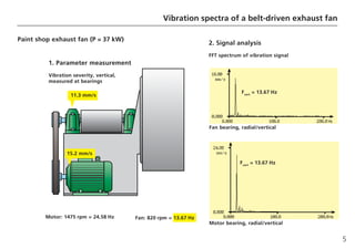
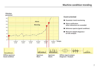
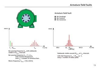
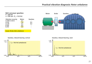
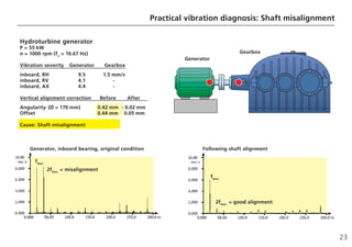
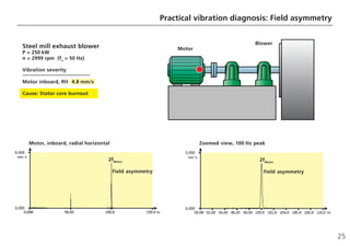
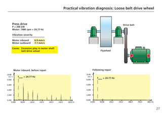
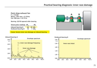
This document discusses machine vibration diagnosis through FFT analysis. It provides examples of using FFT analysis to diagnose issues like rotor unbalance, shaft misalignment, field asymmetry, and a loose belt drive wheel. FFT analysis allows identifying fault frequencies in the machine's vibration spectrum to pinpoint the root cause of issues. The document also discusses ISO standards for vibration severity, components vulnerable to damage, and practical diagnosis techniques.
Machinery Vibration Analysis and Maintenance Living Online
This practical workshop provides a detailed examination of the detection, location and diagnosis of faults in rotating and reciprocating machinery using vibration analysis. The basics and underlying physics of vibration signals are first examined. The acquisition and processing of signals is reviewed followed by a discussion of machinery fault diagnosis using vibration analysis, and rectifying the unidentified faults. The workshop is concluded by a review of the other techniques of predictive maintenance such as oil and particle analysis, ultrasound and infrared thermography. The latest approaches and equipment used together with current research techniques in vibration analysis are also highlighted in the workshop.
MORE INFORMATION: http://www.idc-online.com/content/practical-machinery-vibration-analysis-and-predictive-maintenance-11
Tugas Getaran Mekanis Oleh :
1. Thareq Akbar Arya Yudhistira (15/381210/TK/43388)
2. Muhammad Khautal Ardi Putra (15/381352/TK/43420)
3. Maurissa Hasina Rosyi (15/381209/TK/43387)
4. I Nyoman Nalendra (15/380152/TK/43336)
Vibration Analysis, Emerson Makes it Easy for YouDieter Charle
One of the most powerful tools to deploy reliability centered maintenance are portable vibration measurements. With the new portable vibration analyser of Emerson, portable vibration analysis is now made easier than ever before. By the following slidedeck you'll get an introduction to the basics of vibration analysis and the capabilities of the CSI2140
This presentation is equipped with the basic concepts of Condition Monitoring. The methods and analysis, circumscribed by Condition Monitoring, are summarized with an addition of application in this presentation.
Assessment of Gearbox Fault DetectionUsing Vibration Signal Analysis and Acou...IOSR Journals
Maintenance is a set of organised activities that are carried out in order to keep an item in its best
operational condition with minimum cost acquired. Predictive maintenance (PdM) is one of the maintenance
program that recommends maintenance decisions based on the information collected through condition
monitoring techniques, statistical process control or equipment performance for the purpose of early detection
and elimination of equipment defects that could lead to unplanned downtime of machinery or unnecessary
expenditures. Particularly Gears and rolling element bearings are critical elements in rotating machinery, so
predictive maintenance is often applied to them. Fault signals of gearboxes or rolling-element bearings are nonstationary.
This paper concludes with a brief discussion on current practices of PDM methodologies such as
vibration analysis and Acoustic Emission analysis, which are widely used as they offers a complimentary tool
for health monitoring or assessment of gears in rotating machineries
A gas turbine is a combustion engine at the heart of a power plant that can convert natural gas or other liquid fuels to mechanical energy. This energy then drives a generator that produces the electrical energy that moves along power lines to homes and businesses.
Presentation on Condition Based Monitoring for gas turbine engines is discussed briefly.
A Wavelet Based fault Detection of Induction Motor: A Reviewijsrd.com
This paper presents a review of the researches done on fault detection and tolerant control , main aim of the fault tolerant control and fault detection of induction motor is used the wavelet transform. Wavelet transform is much better tool for the fault diagnosis point of view and a overview of the wavelet types (continuous and discrete), machine faults detection methods and their validation. The software, generality of codes, one dimensional and two dimensional DWT and frequency characteristics components of healthy as well as faulty induction motor has explained. So Finally, stator short winding , shaft fault, bearing fault ,rotor broken bar and open winding are taken as a case study to show the better diagnosis of fault by using wavelet techniques.
Welcome to TechSoup New Member Orientation and Q&A (May 2024).pdfTechSoup
In this webinar you will learn how your organization can access TechSoup's wide variety of product discount and donation programs. From hardware to software, we'll give you a tour of the tools available to help your nonprofit with productivity, collaboration, financial management, donor tracking, security, and more.
2024.06.01 Introducing a competency framework for languag learning materials ...Sandy Millin
http://sandymillin.wordpress.com/iateflwebinar2024
Published classroom materials form the basis of syllabuses, drive teacher professional development, and have a potentially huge influence on learners, teachers and education systems. All teachers also create their own materials, whether a few sentences on a blackboard, a highly-structured fully-realised online course, or anything in between. Despite this, the knowledge and skills needed to create effective language learning materials are rarely part of teacher training, and are mostly learnt by trial and error.
Knowledge and skills frameworks, generally called competency frameworks, for ELT teachers, trainers and managers have existed for a few years now. However, until I created one for my MA dissertation, there wasn’t one drawing together what we need to know and do to be able to effectively produce language learning materials.
This webinar will introduce you to my framework, highlighting the key competencies I identified from my research. It will also show how anybody involved in language teaching (any language, not just English!), teacher training, managing schools or developing language learning materials can benefit from using the framework.
The Indian economy is classified into different sectors to simplify the analysis and understanding of economic activities. For Class 10, it's essential to grasp the sectors of the Indian economy, understand their characteristics, and recognize their importance. This guide will provide detailed notes on the Sectors of the Indian Economy Class 10, using specific long-tail keywords to enhance comprehension.
For more information, visit-www.vavaclasses.com
The Art Pastor's Guide to Sabbath | Steve ThomasonSteve Thomason
What is the purpose of the Sabbath Law in the Torah. It is interesting to compare how the context of the law shifts from Exodus to Deuteronomy. Who gets to rest, and why?
The French Revolution, which began in 1789, was a period of radical social and political upheaval in France. It marked the decline of absolute monarchies, the rise of secular and democratic republics, and the eventual rise of Napoleon Bonaparte. This revolutionary period is crucial in understanding the transition from feudalism to modernity in Europe.
For more information, visit-www.vavaclasses.com
Unit 8 - Information and Communication Technology (Paper I).pdfThiyagu K
This slides describes the basic concepts of ICT, basics of Email, Emerging Technology and Digital Initiatives in Education. This presentations aligns with the UGC Paper I syllabus.
Ethnobotany and Ethnopharmacology:
Ethnobotany in herbal drug evaluation,
Impact of Ethnobotany in traditional medicine,
New development in herbals,
Bio-prospecting tools for drug discovery,
Role of Ethnopharmacology in drug evaluation,
Reverse Pharmacology.
Students, digital devices and success - Andreas Schleicher - 27 May 2024..pptxEduSkills OECD
Andreas Schleicher presents at the OECD webinar ‘Digital devices in schools: detrimental distraction or secret to success?’ on 27 May 2024. The presentation was based on findings from PISA 2022 results and the webinar helped launch the PISA in Focus ‘Managing screen time: How to protect and equip students against distraction’ https://www.oecd-ilibrary.org/education/managing-screen-time_7c225af4-en and the OECD Education Policy Perspective ‘Students, digital devices and success’ can be found here - https://oe.cd/il/5yV
Read| The latest issue of The Challenger is here! We are thrilled to announce that our school paper has qualified for the NATIONAL SCHOOLS PRESS CONFERENCE (NSPC) 2024. Thank you for your unwavering support and trust. Dive into the stories that made us stand out!
4. 4
Let us examine a simple practical example to
illustrate the possibilities of vibration analysis:
a belt-driven fan unit had failed due to
excessive vibration. Since the most severe
vibration level was measured on the drive
motor, the motor seemed the logical candi-
date for examination. Vibration analysis
showed, however, that the extremely severe
vibration (15.2 mm/s) at the motor was occur-
ring primarily at a frequency which was con-
ducted to the motor via the belt drive. When
the belt drive wheel on the fan was balanced,
vibration decreased to acceptable levels of
2.3 mm/s on the fan and 3.2 mm/s on the
drive motor.
This case presents a typical method of opera-
tion: a simple measurement of overall vibra-
tion level allows the machine condition to be
rated as ‘good’, ‘satisfactory’, ‘unsatisfactory’
and ‘unacceptable’. In the case of excessive
vibration, the root cause - drive belt wheel
unbalance - was made clear by checking the
frequency peaks in the FFT vibration spec-
trum.
2. Vibration spectra of a belt-driven exhaust fan
5. 5
Vibration spectra of a belt-driven exhaust fan
Paint shop exhaust fan (P = 37 kW)
1. Parameter measurement
Vibration severity, vertical,
measured at bearings
Motor: 1475 rpm = 24.58 Hz Fan: 820 rpm = 13.67 Hz
15.2 mm/s
11.3 mm/s
Fan bearing, radial/vertical
Fvert
= 13.67 Hz
Fvert
= 13.67 Hz
Motor bearing, radial/vertical
2. Signal analysis
FFT spectrum of vibration signal
6. 6
3. Machine condition trending
A rational approach to successful and effec-
tive condition monitoring is that of trending
the development of characteristic overall val-
ue measurements of machine condition over
time. The trend readings are plotted as shown
here and compared with appropriate warning
and alarm thresholds. When thresholds are
exceeded (and not before then), detailed
vibration diagnosis is performed in order to
locate the exact source of trouble and to
determine the corresponding maintenance
remedy. Let us examine, then, the vibration
monitoring and diagnosis techniques that
hold particular relevance for electric motors.
8. 8
Machine condition monitoring calls for mea-
surement of suitable vibration characteristic
overall values, which allow the general vibra-
tion condition of the machine to be estimat-
ed. The trend development of these charac-
teristic overall values points out condition
deterioration, i.e. damage progression. This
type of overall vibration measurement is char-
acterized as ‘Level 1’ as shown here. It allows
monitoring of many aggregates without im-
posing high demands in terms of equipment
and manpower.
Characteristic overall value (Level 1) measure-
ments such as these, however, are insufficient
for precise localization of defects, as this
requires closer analysis of the machine spec-
trum. Most types of damage can be detected
by their characteristic frequencies or typical
pattern of frequencies. ‘Level 2’ vibration
4. Level 1 / Level 2 condition monitoring strategy
diagnosis normally requires measurement of
vibration signals using an FFT vibration analyz-
er by trained personnel who are experienced
in interpreting vibration spectra.
9. 9
Level 1 / Level 2 condition monitoring strategy
Level 2: Vibration diagnosis
following alarm violation
- Isolated
- One-time
- Specialist
Machine monitoring
Vibration load
Bearing condition
Parameters
Vibration strength, displacement, acceleration
Shock pulse for bearing evaluation
Temperature
RPM
Pump cavitation
Defect localization via spectrum analysis
Rotor unbalance, shaft misalignment, gear damage,
turbulence, field faults, bearing diagnosis etc.
Signal analysis
Amplitude spectrum
Envelope spectrum
Time signal
Ordinal analysis
Cepstrum
Level 1: Parameter trend monitoring
- Comprehensive
- Long-term
- Less-skilled personnel
10
8
6
4
2
0
0 500 1000 1500
a
mm/s2
veff
mm/s
tem-
po
10
8
6
4
2
0
f in Hz
10. 10
DIN ISO 10816-3 plays a very
important role for mainte-
nance technicians in the eval-
uation of machine vibrations.
Part 3 of this standard, which
is the section that is of rele-
vance to Condition Monitor-
ing, has been revised. Groups
3 and 4 of Part 3, which dealt
with pumps, have been re-
moved. Instead, the standard
was expanded to include Part
7 – namely, DIN ISO 10816-7.
This new part deals entirely
with vibrations in centrifugal
pumps.
The new DIN ISO 10816-7 has
been in effect since August
2009.
5. Vibration severity according to ISO standards
12. 12
This illustration gives an overview of the
electric motor components most vulnerable
to damage. Some types of damage exhibit
typical vibration spectra patterns, and each of
these phenomena shall now be explained in
detail.
6. Motor components vulnerable to damage
14. 14
Unbalance is understood to be an eccentric
distribution of rotor mass. When an unbal-
anced rotor begins to rotate, the resulting
rotating centrifugal force produces additional
forces on bearings and rotor vibration at the
exact frequency of rotation. This characterizes
the spectrum of an unbalanced machine, i.e.
the rotation frequency appears as a ‘peak’
with elevated amplitude, and this can signifi-
cantly degrade the overall vibration condition
of the machine. The necessary redistribution
of rotor mass is achieved by balancing the
motor rotor either with a balancing machine
following disassembly or on-site using a vibra-
tion-based balancing instrument. Reference
#3 indicates acceptable residual unbalance
for rigid rotors.
Shaft misalignment of directly coupled ma-
chines results primarily in elevated vibration at
twice the shaft rotation frequency, sometimes
with the peak at shaft rotation frequency
elevated as well. If the radial misalignment
(i.e. shaft offset) dominates, then this peak is
most pronounced for measurements taken in
radial direction (perpendicular to the shafts).
If angular misalignment (coupling gap) is
predominant, then vibration elevation will be
most noticeable in frequency spectra of axial
measurements. Many manufacturers and op-
erators of electric machines have adopted the
use of modern laser-optical shaft alignment
systems such as OPTALIGN®
to correct exces-
sive shaft misalignment. Recommended align-
ment tolerances are outlined in Note #4.
7. Rotor unbalance / Shaft misalignment
3
ISO 3945
Mechanical vibration of large rotating machines with
speed range from 10 to 200 rev/s; Measurement and
evaluation of vibration severity in situ, 12/1985
4
OPTALIGN®
PLUS
Operating instructions and alignment handbook,
PRÜFTECHNIK AG, Ismaning, Germany, 03/1997
15. 15
Unbalance
Amplitude of fn
too high
■
■
■
■
■ Rotation frequency fn
= rpm/60
■
■
■
■
■ Evaluation standard: ISO 2372, ISO/DIS 10816-3
Shaft misalignment
Twice (2x) rotation frequency 2fn
■
■
■
■
■ Radial: radial misalignment
■
■
■
■
■ Axial: axial misalignment
f in Hz
fn
2fn
mm/s
f in Hz
mm/s
fn
Rotor unbalance / Shaft misalignment
16. 16
Field asymmetry of electric motors can be
caused by stator or rotor (armature) defects.
The most common faults are
• Motor core short circuiting from armature
rubbing or burnout
• Asymmetrical winding
• Asymmetrical power feed and
• Eccentric armature position.
Stator field defects can be recognized in the
vibration spectrum as peaks occurring at
twice the mains frequency, without side-
bands.
8. Stator field asymmetry
17. 17
Stator field asymmetry
2fMains
Twice mains frequency 2fMains
visible
Mains frequency fMains
= 50 or 60 Hz
Exception: rectifier drives
No sidebands visible around 2fMains
2-pole machines:
2x rotation frequency lies just below 2fMains
99.0 101.0
f in Hz
fn
mm/s
f in Hz
2fn
2fMains
mm/s
Stator field asymmetry
■
■
■
■
■ Core burnout, short circuit
■
■
■
■
■ Eccentric armature position
■
■
■
■
■ Asymmetric power feed
■
■
■
■
■ Asymmetric winding
18. 18
Rotor field asymmetry is caused by:
• Damaged bars (breakage/fracturing, loose-
ness) or
• Short circuited bars or
• Short circuited rings (breakage/fracturing)
or
• Short circuited armature packs (e.g. by
overloading at excessive speed)
These faults can be detected in the vibration
spectrum by the evidence of
• Bar passing frequency with sidebands at
twice the mains frequency and
• Mains frequency with sidebands at slipping
frequency.
The only possible remedy here is usually
complete replacement of the armature.
9. Armature field faults
19. 19
Armature field faults
Bar passing frequency fbar
with sidebands
visible at 2fMains
intervals
Bar passing frequency fbar
= fn
x nbar
with rotation frequency fn
and nbar
= number of armature bars
Mains frequency: fMains
= 50 or 60 Hz
Sidebands visible around 2fMains
at fslip
intervals
with slip frequency fslip
= 2fMains
/p - fn
and p = number of stator poles
99.0 101.0 f in Hz
2fn
2fMains
(100 Hz)
mm/s
fbar
f in Hz
fn
2fMains
mm/s
Armature field fault
■
■
■
■
■ Bar breakage
■
■
■
■
■ Bar fracture
■
■
■
■
■ Bar looseness
20. 20
The vibration spectrum exhibits a typical un-
balance pattern. The levels of vibration severi-
ty measured at several locations on the ma-
chine point indicate that the source of excita-
tion lies near the coupling. Simple rotor bal-
ancing of the brake disk reduced motor
vibration to 3.5 mm/s and gearbox vibration
to 3.1 mm/s.
10. Practical vibration diagnosis: Rotor unbalance
21. 21
Practical vibration diagnosis: Rotor unbalance
Belt conveyor gearbox
P = 600 kW
n = 996 rpm (fn
= 16.6 Hz)
Vibration severity Motor Gearbox
A, RH in mm/s 3.1 -
A, RV 7.8 9.2
A, AX 5.3 6.2
B, RH 4.4 -
B, RV 6.8 -
Cause: Brake disk unbalance
Gearbox, inboard bearing, vertical Gearbox, inboard bearing, axial
Gearbox
Brake
Motor
fn
= 16.6 Hz (unbalance)
fn
= 16.6 Hz (unbalance)
22. 22
The vibration spectrum shows a distinct peak
at twice the shaft rotation frequency, which
clearly indicates shaft misalignment. Follow-
ing shaft alignment, the peak has disap-
peared, but the rotor unbalance evident in the
previous spectrum remains to be corrected.
11. Practical vibration diagnosis: Shaft misalignment
23. 23
Practical vibration diagnosis: Shaft misalignment
Hydroturbine generator
P = 55 kW
n = 1000 rpm (fn
= 16.67 Hz)
Vibration severity Generator Gearbox
inboard, RH 9.5 1.5 mm/s
inboard, RV 4.1 -
inboard, AX 4.4 -
Vertical alignment correction Before After
Angularity (Ø = 170 mm) 0.42 mm - 0.02 mm
Offset 0.44 mm 0.05 mm
Cause: Shaft misalignment
Generator, inboard bearing, original condition Following shaft alignment
fGen.
2fGen.
= misalignment
fGen.
2fGen.
= good alignment
Gearbox
Generator
24. 24
The motor had drawn attention due to elevat-
ed vibration which also occurred with the
coupling removed. The unusually high peak at
twice the line frequency pointed toward sta-
tor damage. Disassembly revealed that the
stator packet had burned out due to local
short circuiting of the core. The motor had to
be completely replaced.
12. Practical vibration diagnosis: Field asymmetry
25. 25
Practical vibration diagnosis: Field asymmetry
Steel mill exhaust blower
P = 250 kW
n = 2999 rpm (fn
= 50 Hz)
Vibration severity
Motor inboard, RH 4.8 mm/s
Cause: Stator core burnout
Motor, inboard, radial horizontal Zoomed view, 100 Hz peak
2fMains
Field asymmetry
2fMains
Field asymmetry
Motor
Blower
26. 26
A press drive motor had developed severe
vibration and was producing unusual noises
that had become more pronounced from one
day to the next. In stark contrast to the usual
vibration spectrum, the rotation frequency
was hardly visible at all, but multiples of the
rotation frequency were quite obvious. These
symptoms remained unchanged when the
drive belt was removed from the motor. The
source was found to be loose mounting of the
belt drive wheel on the motor shaft. The
problem was resolved by remachining the
motor shaft and reattaching the belt drive
wheel.
13. Practical vibration diagnosis: Loose belt drive wheel
27. 27
Practical vibration diagnosis: Loose belt drive wheel
Press drive
P = 200 kW
Motor: 1486 rpm = 24.77 Hz
Vibration severity
Motor inboard 6.9 mm/s
Motor outboard 7.1 mm/s
Cause: Excessive play in motor shaft
belt drive wheel
Motor inboard, before repair Following repair
fmotor
= 24.77 Hz
Flywheel
Drive belt
fmotor
= 24.77 Hz
28. 28
As a rule, bearing race damage cannot be
detected by elevated levels of low-frequency
vibration parameters until damage is quite
severe. The reason for this is that when the
rolling elements pass over a damaged area of
the race, a shock pulse is created that can be
detected only in the high-frequency range at
first. This is why special bearing characteristic
overall values were developed for anti-friction
bearing monitoring; there is no international-
ly-accepted standard for these so far, and so a
variety of different characteristic overall val-
ues can be found in use today.
This illustration lists the most well-known of
these bearing parameters. In Germany, for
example, the shock pulse method has estab-
lished itself over the past 25 years as an easy-
to-use and reliable measurement technique
for monitoring anti-friction bearings. In con-
trast to all other bearing parameters, this
method uses two parameters for evaluation.
The shock pulse maximum value dBm, which
indicates the severity of shocks in the rolling
behavior of the bearing, is useful in detecting
initial damage to bearing races. The ‘carpet
level’ of shock pulses, dBc, indicates the base
noise level of the bearing, which increases
primarily due to lubrication problems, general
wear of races, insufficient bearing clearance
or residual stress due to improper installation.
One typical characteristic of all anti-friction
bearing parameters is the dependency of their
levels upon various influences such as rolling
velocity, i.e. bearing size and rpm, signal
damping, bearing load and lubrication. This is
why it is practically always necessary to take a
comparative measurement in good condition
or to normalize readings relative to good
condition.
14. Bearing evaluation characteristic overall values
30. 30
This illustration shows the normalization pro-
cedure that PRÜFTECHNIK instruments use
during shock pulse measurement to compen-
sate the influence of rolling velocity differenc-
es. The initial level, and in turn the adjusted
initial value dBia, are determined by taking a
comparative measurement in good condition.
This serves as the reference for relative level
measurement of maximum shock pulse value
dBm and the shock pulse carpet value dBc.
This procedure allows measurements from
different bearings to be compared using the
same level scale so that tolerances do not
have to be set individually for every single
measurement location.
15. Normalization of shock pulse measurement
31. 31
Normalization of shock pulse measurement
Non-normalized measurement
Shock pulse peak value dBm
and carpet value dBc
as absolute level in dBsv
Normalized measurement
Shock pulse max. value dBm
and carpet value dBc
as relative level in dBsv
referenced to dBia
value
■
■
■
■
■ Threshold (limit) values set individually
for every single location
dBm
dBC
Normalization
dBm
dBC
dBia
Alarm
Warning
Alarm
Warning
■
■
■
■
■ dBia
value includes influence factors such as rolling
velocity, signal damping, bearing load
■
■
■
■
■ Different threshold limits are linked to the setup dBia
value; the same predefined threshold values are used
for all locations
dBn
40
dBsv
70
0
0
32. 32
Similarly to vibration diagnosis via frequency
spectrum measurement, in-depth diagnosis of
anti-friction bearings may be performed
through analysis of the signal ‘envelope’.
The illustrations here explain the envelope
analysis procedure, which begins with filter-
ing out the appropriate range of frequencies
that contain the signal emitted by the bearing
during operation. This signal component is
examined for the pulses that arise when
bearing elements roll over damaged loca-
tions. Demodulation is used to calculate a
curve that ‘envelops’ the bearing signal. If the
time interval between periodically-occurring
peaks in the envelope curve match one of the
critical frequencies characteristic of bearing
damage, then the corresponding bearing
component can be assumed to be damaged.
16. Anti-friction bearing damage diagnosis
This procedure allows extremely accurate di-
agnosis of damage to anti-friction bearings,
even in cases where extraneous signal compo-
nents such as gear meshing noise tend to
cover up the actual bearing signal. It does
require knowledge of certain geometric data
of the bearing, including the bearing diame-
ter, the number and diameter of rolling ele-
ments, the load angle and the operating
speed.
33. 33
Anti-friction bearing damage diagnosis
Time signal Time signal
Ta
f in Hz
Damage
No damage
a, m/s²
a, m/s²
a, m/s²
Envelope curve
Envelope curve
Envelope curve spectrum
t in s
t in s
Envelope curve spectrum
a, m/s²
fa
2fa
etc. f in Hz
Damage frequency fa
= 1/Ta
34. 34
This shows an example of advanced damage
to the inner race. The great increase in shock
pulse levels, especially that of peak value dBm
from 18 to 48 dBsv, signified serious bearing
damage. Envelope spectrum analysis indicat-
ed a pattern typical of inner race damage,
which was then confirmed following bearing
replacement: one of the two races of the
inner ring already exhibited a damaged sur-
face area of about 15 x 15 mm / 5/8” x 5/8”.
17. Practical bearing diagnosis: inner race damage
35. 35
Practical bearing diagnosis: inner race damage
fi
= inner race damage frequency Inner race intact
Inboard bearing A Outboard bearing B
Envelope spectrum Envelope spectrum
Paint shop exhaust fan
P = 110 kW
Motor: 1307 rpm = 21.78 Hz
Fan: 908 rpm = 35.75 Hz
Bearing: 22218 tapered roller bearing
Shock pulse readings dBm
dBc
Inboard bearing A 48 29 dBSV
Outboard bearing B 18 7 dBSV
Cause: Severe inner race damage on inboard bearing
Inner race damage
A B
36. 36
PRÜFTECHNIK AG
Oskar-Messter-Str. 19-21
85737 Ismaning, Germany
Tel.: +49 89 99616-0
Fax: +49 89 99616-300
eMail: info@pruftechnik.com
www.pruftechnik.com
Productive maintenance technology
A member of the PRÜFTECHNIK Group