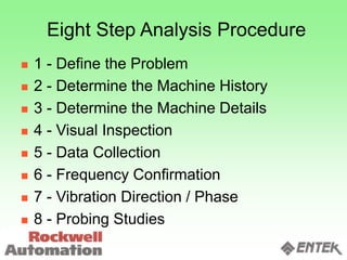
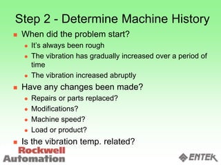
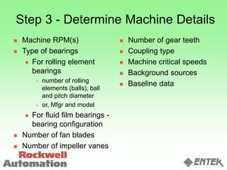
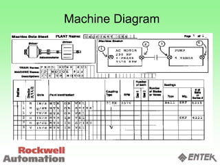
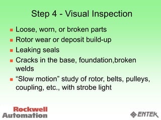
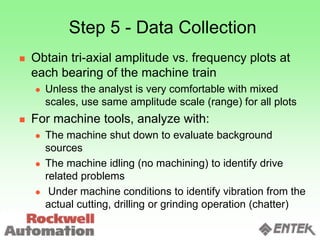
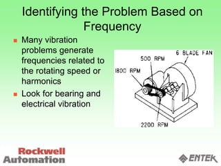
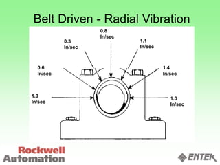
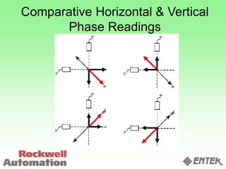
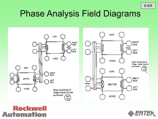
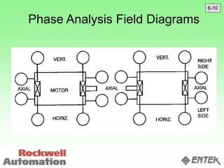
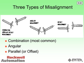
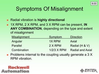
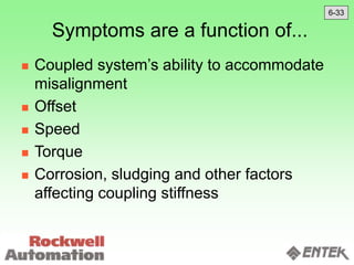
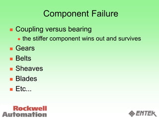
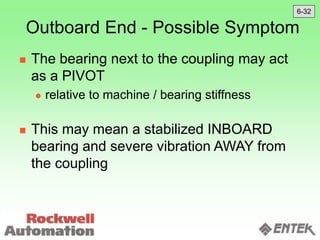
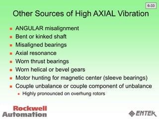
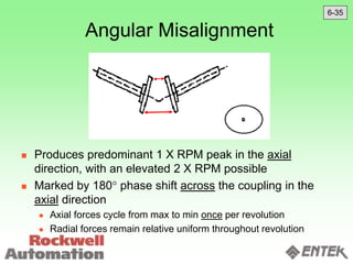
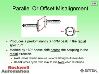
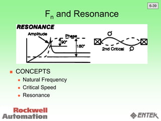
Chapter 6
Vibration Spectrum Analysis & Diagnostics
(Part 1)
(Unbalance - Resonance)
Analysis
A Logical Process
 What is the problem ?
 What are the symptoms ?
 What machine information do I have ?
 What data should I take ?
 Where should I take data ?
Eight Step Analysis Procedure
 1 - Define the Problem
 2 - Determine the Machine History
 3 - Determine the Machine Details
 4 - Visual Inspection
 5 - Data Collection
 6 - Frequency Confirmation
 7 - Vibration Direction / Phase
 8 - Probing Studies
Step 1 - Define the Problem
 Bearing, seal, or other frequent component
failures
 Structural failures
 Inability to manufacture a quality product
(machine tools)
 Physical annoyance / noisy
 Vibration is excessive
 Does not meet performance standards
 (API, ISO, AGMA, etc.)
Step 2 - Determine Machine History
 When did the problem start?
 It’s always been rough
 The vibration has gradually increased over a period of
time
 The vibration increased abruptly
 Have any changes been made?
 Repairs or parts replaced?
 Modifications?
 Machine speed?
 Load or product?
 Is the vibration temp. related?
Step 3 - Determine Machine Details
 Machine RPM(s)
 Type of bearings
 For rolling element
bearings
 number of rolling
elements (balls), ball
and pitch diameter
 or, Mfgr and model
 For fluid film bearings -
bearing configuration
 Number of fan blades
 Number of impeller vanes
 Number of gear teeth
 Coupling type
 Machine critical speeds
 Background sources
 Baseline data
Machine Diagram
Step 4 - Visual Inspection
 Loose, worn, or broken parts
 Rotor wear or deposit build-up
 Leaking seals
 Cracks in the base, foundation,broken
welds
 “Slow motion” study of rotor, belts, pulleys,
coupling, etc., with strobe light
Step 5 - Data Collection
 Obtain tri-axial amplitude vs. frequency plots at
each bearing of the machine train
 Unless the analyst is very comfortable with mixed
scales, use same amplitude scale (range) for all plots
 For machine tools, analyze with:
 The machine shut down to evaluate background
sources
 The machine idling (no machining) to identify drive
related problems
 Under machine conditions to identify vibration from the
actual cutting, drilling or grinding operation (chatter)
Step 6 - Frequency Confirmation
 Determine if vibration frequencies are
EXACTLY related to machine RPM(s)
using:
 Strobe light
 Time-Synchronous averaging
 High resolution FFT
 Fmax 0-12,000 CPM
 #FFT Lines - 3200 (minimum)
Step 6 - Frequency Confirmation
 Fmax needs to be high enough to catch all
defect frequencies in machine
 Resolution needs to be sharp enough to
separate closely spaced frequencies
 Some machines may require more than
one set of FFT’s in order to capture all
problem frequencies with sufficient
resolution for analysis
Identifying the Problem Based on
Frequency
 Many vibration
problems generate
frequencies related to
the rotating speed or
harmonics
 Look for bearing and
electrical vibration
Step 7 - Vibration Direction / Phase
 Determine if the vibration is directional or
non-directional by:
 Comparing the horizontal and vertical phase
readings
 Taking radial vibration amplitude readings
every 30° around each bearing
FFT’s Should Be Compared by
Direction: H,V,A
 How do radial (horizontal and vertical)
readings compare to each other
 How do radial readings compare with axial
measurements
Comparing Radial Amplitudes
Comparing Radial And Axial
Measurements
 Only a few machine defects can cause high
axial readings
 These include Misalignment, Bent Shafts, or
Unbalance of Overhung Rotors
 General Rule:
 Any time the axial amplitude exceeds 50% of
the highest radial, these defects should be
strongly considered
Belt Driven - Radial Vibration
1.0
In/sec
0.6
In/sec
0.3
In/sec
0.8
In/sec
1.1
In/sec
1.4
In/sec
1.0
In/sec
Comparative Horizontal & Vertical
Phase Readings
Phase Analysis Field Diagrams
6-8/9
Phase Analysis Field Diagrams
6-10
Step 8 - Probing Studies
 Base/foundation
 Piping and other related components
 Across all mounting interfaces
 Background machinery
Waveforms and FFT Harmonics
Example Sinusoidal Waveform
Example Square Wave
Unbalance
Types, Symptoms, and Correction
6-11
Rotor Unbalance Characteristics
Can Only Cause 1X RPM Vibration 
 WARNING: 1X not ALWAYS from unbalance
 Amplitude proportional to distance between
center of mass and center of rotation
 Uniform rotating force, changing in direction
and evenly applied radially
 since mobility or “dynamic sensitivity” may
differ between H and V axes, amplitudes may
also differ
6-12
Rotor Unbalance Characteristics
 A dominant unbalance shows 90° phase
difference between H and V
 within usual 30° tolerance
 Horizontal phase difference between
inboard and outboard bearings should
match vertical phase difference
 Radial vibration much greater than axial
vibration
 Overhung rotors are the exception
6-12
Rotor Unbalance Characteristics
 Repeatable phase in all directions
 except for minor beats and “chasing” phases
when balance has been largely corrected
 May be amplified by resonance
 May be the force behind the evidence of
looseness
6-12
 Static Unbalance
 The central principal axis is displaced parallel to the shaft axis
 The unbalance is even at both ends, and is in the same direction
 Couple Unbalance
 The central principal axis intersects the shaft axis at the rotor
center of gravity
 The unbalance is even at both ends, but in the opposite direction
 Quasi-Static Unbalance
 A combination of static and couple unbalance where central
principal axis intersects the shaft axis, but NOT at the rotor center
of gravity
 Dynamic Unbalance
 A random combination of static and couple unbalance
 The centerline of unbalance does not intersect the centerline of
the shaft
Types Of Unbalance
6-11
Phase & Unbalance
6-13
Static (Force) Unbalance
SHAFT AXIS
BALANCE AXIS
 Vibration amplitude and phase readings measured at the
two supporting bearings will be nearly identical
 This unbalance can be solved with a single weight placed
in the center of the rotor, or with two identical weights
placed at the same location on each end
6-14
 Vibration amplitudes will be reasonably the
same, but phase readings at the bearings will
differ by 180°
 This unbalance can be solved with identical
weights placed at each end of the rotor 180°
apart
Coupled Unbalance
SHAFT AXIS
BALANCE AXIS
6-15
Quasi-Static Unbalance
SHAFT AXIS
BALANCE AXIS
 A Static (or Coupled) Unbalance where vibration
amplitudes at one support are considerably
higher than the other and phase readings are the
same (or differ by 180°)
  MOST COMMON TYPE OF UNBALANCE CONDITION
 Accounts for any condition that does not meet the
requirements for static, couple or quasi-static unbalance.
 Note that the balance axis does not pass through the shaft
centerline
Dynamic Unbalance
SHAFT AXIS
BALANCE AXIS
6-15
Cross Effect
 A heavy spot of unbalance located at one
end of a rotor will not only create unbalance
vibration at that end, but will also create
some unbalance vibration at the opposite
end of the rotor as well
Overhung Rotors
 Axial often greater than
radial
 due to couple effect
 Inboard axial phase
should equal outboard
axial phase
 Usually corrected by:
 Static first:
 Brg 2, Plane A
 Then coupled:
 Brg 1, Equal weights in
Planes A and B, 180° apart
6-16
Residual Unbalance
 Rotor Sensitivity =
 Trial Wt. Size X Mounting Radius
Trial Wt. Effect (amplitude)
 Trial weight effect is measured through the
vector length in the vector diagram
calculation during balancing
 Residual Unbalance =
 Rotor Sensitivity X Final Balance Amplitude
6-21
ISO-1940 Balance Grades
6-23
ISO-1940 Balance Grades 6-23
6-24
6-25
A Tolerable Residual
Unbalance for Modern
General Purpose Machines...
To satisfy MIL-STD and API, we should
meet ISO 1940 G 2.5
6-20
ISO 1940 G(rade) 6.3
 Means 6.3 mm/sec Peak
 Corresponds to  0.25 in/sec Peak
 NOT AN ACCEPTABLE STANDARD for
General Purpose Machines in 2000 and
beyond
 G 2.5 corresponds to  0.1in/sec Peak
 This balance specification should be readily
achievable (for most machines) using modern
equipment and balancing techniques
6-20
Eccentric Rotors
The physical center of the shaft does
not line up with the rotational centerline
of the shaft
6-27
 Characterized by MAXIMUM 1X RPM amplitude
along an axis passing through shaft centerlines
 A 90° change in transducer orientation yields 0° or
180° phase change
Eccentric Rotor
6-28
Eccentric Behavior
 Gears have variation in mating force along
centerline of gears
 Sheaves have vibration along centerline of
driver and driven pulley
 Eccentric Motor Armature causes moving
unbalanced magnetic forces
 2X Line Freq. And Pole Pass Freq.
 Eccentric Stator will show a line of maximized
vibration
 Eccentric bearings rarely cause a problem
because of precision manufacture
 when reaching late stages of deterioration, a
bearing may exhibit eccentric behavior
 Eccentric impellers may cause a hydraulic
unbalance between stationary and moving
vanes (high vibration at BPF and harmonics)
6-28
Eccentric Rotors
 Balancing attempts may cause a drop of
amplitude in one radial direction with a
simultaneous increase in another
 May cause significantly HIGHER vibration
in one radial direction than another
6-29
Bent or Kinked Shaft
Kinked - Bent at or near one bearing
Bent - Uniform bow between bearings
6-30
Bent Shaft
 Common causes of a bent shaft
 Manufacturing or machining errors
 Mishandling during transportation
 “Bow” due to thermal growth or uneven heating
due to rotor bar problems
 Sag from sitting in one spot for extended time
 Two types of bent shaft
 Kinked Shaft - Bend is at or near one bearing
 Bowed Shaft - Bend is uniform between two
bearings
6-30
Bent Shaft Symptoms
 Predominant vibration is at 1 X RPM. This
can be accompanied by a 2 X RPM peak
 Axial vibration amplitude normally exceeds
50% of highest radial amplitude
 Radial vibration is usually uniform
 Axial phase analysis must be used to verify
problem and type of bend
6-30
Identifying a Kinked Shaft
 Produces a twisting motion of the bearing
 Axial phase readings taken 90° apart will produce
a phase shift of 90°.
6-31
Bowed Shaft
6-31
A Critical Speed LOOKS like a Bent
Shaft
 A rotor operating close to or at a critical
speed may exhibit “bent shaft” behavior
 Shaft deflection is possibly imitating bent
shaft behavior
6-31
Electric Motors
 A growing vibration amplitude may indicate
shorted laminations…
 the localized heating imposes a shaft bend
as the rotor heats up
 may straighten or not, depending on whether
the bending exceeds elastic limits (reaches
permanent or plastic limits)
6-31
Misalignment
Still the most common source of vibration
(except in plants where PM has been successful
and laser alignment fully implemented)
6-32
Three Types of Misalignment
 Combination (most common)
 Angular
 Parallel (or Offset)
6-32
Misalignment
  MOST COMMON PROBLEM FOUND INITIALLY 
 Temperature changes can affect alignment
 Machines aligned cold can go out when warm
 Different expansion rates in the driver and driven bases can
cause misalignment with changes in ambient temperature
 Bases or foundations can settle
 Shims or bases can rust or corrode
 Grouting can shrink or deteriorate
 May increase energy demands
 More likely to be visible as an increase in RPM when
aligned correctly (power to product, not problem)
6-32
Misalignment (Cont.)
 Resulting forces are shared by driver and driven (not
localized)
 Differences in mass and stiffness may cause different
amplitudes on the driver and the driven, but the frequencies
will be present on both
 The level of misalignment severity is determined by
the machine’s ability to withstand the misalignment
 If the coupling is stronger or more pliable (can withstand
more misalignment) than the bearings, the bearings can fail
with little or no damage to the coupling
 A coupling’s ability to withstand more misalignment does not
reduce the higher forces resulting from this misalignment. It
merely transfers these higher forces to the bearings
6-32
Thermal Growth Rule of Thumb
 On start-up, vibration should start high and
ease up
 the pre-set “misalignment” eases as thermal
growth is achieved
 the machine “grows” (or “shrinks” for cryogenic
applications) into alignment
 Applicable to machines with significant thermal
growth
Symptoms Of Misalignment
 Radial vibration is highly directional
 1X RPM, 2 X RPM, and 3 X RPM can be present, IN
ANY COMBINATION, depending on the type and extent
of misalignment
Misalignment Symptom Direction
Angular 1X RPM Axial
Parallel 2 X RPM Radial (H & V)
Combination 1/2/3 X RPM Radial and Axial
 Problems internal to the coupling usually generate a 3 X
RPM vibration.
6-33
Symptoms are a function of...
 Coupled system’s ability to accommodate
misalignment
 Offset
 Speed
 Torque
 Corrosion, sludging and other factors
affecting coupling stiffness
6-33
Component Failure
 Coupling versus bearing
 the stiffer component wins out and survives
 Gears
 Belts
 Sheaves
 Blades
 Etc...
Outboard End - Possible Symptom
 The bearing next to the coupling may act
as a PIVOT
 relative to machine / bearing stiffness
 This may mean a stabilized INBOARD
bearing and severe vibration AWAY from
the coupling
6-32
Other Sources of High AXIAL Vibration
 ANGULAR misalignment
 Bent or kinked shaft
 Misaligned bearings
 Axial resonance
 Worn thrust bearings
 Worn helical or bevel gears
 Motor hunting for magnetic center (sleeve bearings)
 Couple unbalance or couple component of unbalance
 Highly pronounced on overhung rotors
6-33
PHASE ANALYSIS IS
ESSENTIAL
To assess misalignment or other
abnormal or excessive 1X, 2X and 3X
RPM vibration behavior
6-33
Angular Misalignment
 Produces predominant 1 X RPM peak in the axial
direction, with an elevated 2 X RPM possible
 Marked by 180 phase shift across the coupling in the
axial direction
 Axial forces cycle from max to min once per revolution
 Radial forces remain relative uniform throughout revolution
6-35
Parallel Or Offset Misalignment
 Produces a predominant 2 X RPM peak in the radial
spectrum
 Marked by 180 phase shift across the coupling in the
radial direction.
 Axial forces remain relative uniform throughout revolution
 Radial forces cycle from max to min twice each revolution
6-36
Very Pronounced Parallel
Misalignment on a SINGLE AXIS
 May cause behavior similar to other highly
directional vibration
 might be mistaken for resonance, eccentricity
or the like…
 Highly elliptical shaft orbit (flattened)
6-36
Misalignment Vs. Type C
Looseness
Excessive misalignment (whether
angular or parallel) may generate a
progressively HIGHER number of
running speed harmonics
6-36
Misaligned / Cocked Bearing
 Generates
considerable 1 X RPM
and possibly 2 X RPM
 Axial Twisting motion
 NOT resolved by
balancing or aligning
6-37
Coupling Problems
Reminder: seen in a MISALIGNMENT
context
6-37
Coupling Problems
 Long or short spacer
 noticeable radial 3 X RPM vibration
 much HIGHER axial 3 X RPM vibration
 Gear Type Lock-up
 may cause thrust bearing failure
 mostly 1X RPM with axial > radial
 when misalignment is present
 some mesh (# of grid X RPM) & harmonics
 Christmas Tree (2 X to 6 X, decreasing by 25% for
each harmonic increment
6-38
Coupling Problems
 Loose Coupling
 sidebands around BPF or GMF
 Text: “does not drive rotor at uniform speed
(RPM)”
 when torque is applied continuously, looseness will
not be manifest unless severe misalignment is
present
 Modulation mostly due to occasional shift of
coupling causing a pivoting effect resulting in
eccentric placement of the rotor within casing
6-38
Loose Coupling on Fan Shaft
6-38
Other Types Of Misalignment
Natural Frequency (Fn)
and Resonance
The Importance of Natural
Frequencies
6-39
Fn and Resonance
 CONCEPTS
 Natural Frequency
 Critical Speed
 Resonance
6-39
Fn and Resonance
 Every machine element has natural
frequencies based on mass, shape and
stiffness
 Resonance occurs when a forcing
frequency coincides with one of these
natural frequencies
6-39
VIBRATION DUE TO RESONANCE
 Every object, including every element or part of a
machine, has “natural frequencies” at which “it likes to
vibrate”
 Determined by machine mass and stiffness as well as moment
of inertia (shape) for the concerned axis
 CAN NOT CAUSE VIBRATION , it merely serves
as a “mechanical amplifier” (10x-100x)
 Resonance is a very common cause of excessive
vibration because:
 Machines consist of many individual elements
 Stiffness of each machine component differs in all directions,
meaning several natural frequencies within the range of the
generated forcing frequencies
6-39
Identifying Resonance
 Vibration will be highly directional
 Changing the exciting forcing frequency to
observe reaction
 Change the mass or stiffness of the
suspected resonant machine component
 Perform a bump test
 modally tuned hammer test
6-39
FORCING FREQUENCIES
 Almost ANY frequency present in the
spectrum can become a forcing frequency
 Unbalance, misalignment, torque or blade
pass pulses, harmonics of each, etc.
6-39
6-40
Damping Factor (Q)
6-40
Damping Factor vs. Phase
6-40
Amplification Formula
Identifying Natural Frequencies
6-41
Bode Plot
6-42
6-43
How to Resolve Resonance Problems
 Change stiffness
 Change mass
 Add isolation
 Add damping material
 Install Tune Damper (Vibration Absorber)
 Precision Balancing (last resort)
6-47
Natural Frequency Formulas
6-48

CH6a.ppt

  • 1.
    Chapter 6 Vibration SpectrumAnalysis & Diagnostics (Part 1) (Unbalance - Resonance)
  • 2.
    Analysis A Logical Process What is the problem ?  What are the symptoms ?  What machine information do I have ?  What data should I take ?  Where should I take data ?
  • 3.
    Eight Step AnalysisProcedure  1 - Define the Problem  2 - Determine the Machine History  3 - Determine the Machine Details  4 - Visual Inspection  5 - Data Collection  6 - Frequency Confirmation  7 - Vibration Direction / Phase  8 - Probing Studies
  • 4.
    Step 1 -Define the Problem  Bearing, seal, or other frequent component failures  Structural failures  Inability to manufacture a quality product (machine tools)  Physical annoyance / noisy  Vibration is excessive  Does not meet performance standards  (API, ISO, AGMA, etc.)
  • 5.
    Step 2 -Determine Machine History  When did the problem start?  It’s always been rough  The vibration has gradually increased over a period of time  The vibration increased abruptly  Have any changes been made?  Repairs or parts replaced?  Modifications?  Machine speed?  Load or product?  Is the vibration temp. related?
  • 6.
    Step 3 -Determine Machine Details  Machine RPM(s)  Type of bearings  For rolling element bearings  number of rolling elements (balls), ball and pitch diameter  or, Mfgr and model  For fluid film bearings - bearing configuration  Number of fan blades  Number of impeller vanes  Number of gear teeth  Coupling type  Machine critical speeds  Background sources  Baseline data
  • 7.
  • 8.
    Step 4 -Visual Inspection  Loose, worn, or broken parts  Rotor wear or deposit build-up  Leaking seals  Cracks in the base, foundation,broken welds  “Slow motion” study of rotor, belts, pulleys, coupling, etc., with strobe light
  • 9.
    Step 5 -Data Collection  Obtain tri-axial amplitude vs. frequency plots at each bearing of the machine train  Unless the analyst is very comfortable with mixed scales, use same amplitude scale (range) for all plots  For machine tools, analyze with:  The machine shut down to evaluate background sources  The machine idling (no machining) to identify drive related problems  Under machine conditions to identify vibration from the actual cutting, drilling or grinding operation (chatter)
  • 10.
    Step 6 -Frequency Confirmation  Determine if vibration frequencies are EXACTLY related to machine RPM(s) using:  Strobe light  Time-Synchronous averaging  High resolution FFT  Fmax 0-12,000 CPM  #FFT Lines - 3200 (minimum)
  • 11.
    Step 6 -Frequency Confirmation  Fmax needs to be high enough to catch all defect frequencies in machine  Resolution needs to be sharp enough to separate closely spaced frequencies  Some machines may require more than one set of FFT’s in order to capture all problem frequencies with sufficient resolution for analysis
  • 12.
    Identifying the ProblemBased on Frequency  Many vibration problems generate frequencies related to the rotating speed or harmonics  Look for bearing and electrical vibration
  • 13.
    Step 7 -Vibration Direction / Phase  Determine if the vibration is directional or non-directional by:  Comparing the horizontal and vertical phase readings  Taking radial vibration amplitude readings every 30° around each bearing
  • 14.
    FFT’s Should BeCompared by Direction: H,V,A  How do radial (horizontal and vertical) readings compare to each other  How do radial readings compare with axial measurements
  • 15.
  • 16.
    Comparing Radial AndAxial Measurements  Only a few machine defects can cause high axial readings  These include Misalignment, Bent Shafts, or Unbalance of Overhung Rotors  General Rule:  Any time the axial amplitude exceeds 50% of the highest radial, these defects should be strongly considered
  • 17.
    Belt Driven -Radial Vibration 1.0 In/sec 0.6 In/sec 0.3 In/sec 0.8 In/sec 1.1 In/sec 1.4 In/sec 1.0 In/sec
  • 18.
    Comparative Horizontal &Vertical Phase Readings
  • 19.
    Phase Analysis FieldDiagrams 6-8/9
  • 20.
    Phase Analysis FieldDiagrams 6-10
  • 21.
    Step 8 -Probing Studies  Base/foundation  Piping and other related components  Across all mounting interfaces  Background machinery
  • 22.
  • 23.
  • 24.
  • 25.
  • 26.
    Rotor Unbalance Characteristics CanOnly Cause 1X RPM Vibration   WARNING: 1X not ALWAYS from unbalance  Amplitude proportional to distance between center of mass and center of rotation  Uniform rotating force, changing in direction and evenly applied radially  since mobility or “dynamic sensitivity” may differ between H and V axes, amplitudes may also differ 6-12
  • 27.
    Rotor Unbalance Characteristics A dominant unbalance shows 90° phase difference between H and V  within usual 30° tolerance  Horizontal phase difference between inboard and outboard bearings should match vertical phase difference  Radial vibration much greater than axial vibration  Overhung rotors are the exception 6-12
  • 28.
    Rotor Unbalance Characteristics Repeatable phase in all directions  except for minor beats and “chasing” phases when balance has been largely corrected  May be amplified by resonance  May be the force behind the evidence of looseness 6-12
  • 29.
     Static Unbalance The central principal axis is displaced parallel to the shaft axis  The unbalance is even at both ends, and is in the same direction  Couple Unbalance  The central principal axis intersects the shaft axis at the rotor center of gravity  The unbalance is even at both ends, but in the opposite direction  Quasi-Static Unbalance  A combination of static and couple unbalance where central principal axis intersects the shaft axis, but NOT at the rotor center of gravity  Dynamic Unbalance  A random combination of static and couple unbalance  The centerline of unbalance does not intersect the centerline of the shaft Types Of Unbalance 6-11
  • 30.
  • 31.
    Static (Force) Unbalance SHAFTAXIS BALANCE AXIS  Vibration amplitude and phase readings measured at the two supporting bearings will be nearly identical  This unbalance can be solved with a single weight placed in the center of the rotor, or with two identical weights placed at the same location on each end 6-14
  • 32.
     Vibration amplitudeswill be reasonably the same, but phase readings at the bearings will differ by 180°  This unbalance can be solved with identical weights placed at each end of the rotor 180° apart Coupled Unbalance SHAFT AXIS BALANCE AXIS 6-15
  • 33.
    Quasi-Static Unbalance SHAFT AXIS BALANCEAXIS  A Static (or Coupled) Unbalance where vibration amplitudes at one support are considerably higher than the other and phase readings are the same (or differ by 180°)
  • 34.
      MOSTCOMMON TYPE OF UNBALANCE CONDITION  Accounts for any condition that does not meet the requirements for static, couple or quasi-static unbalance.  Note that the balance axis does not pass through the shaft centerline Dynamic Unbalance SHAFT AXIS BALANCE AXIS 6-15
  • 35.
    Cross Effect  Aheavy spot of unbalance located at one end of a rotor will not only create unbalance vibration at that end, but will also create some unbalance vibration at the opposite end of the rotor as well
  • 36.
    Overhung Rotors  Axialoften greater than radial  due to couple effect  Inboard axial phase should equal outboard axial phase  Usually corrected by:  Static first:  Brg 2, Plane A  Then coupled:  Brg 1, Equal weights in Planes A and B, 180° apart 6-16
  • 37.
    Residual Unbalance  RotorSensitivity =  Trial Wt. Size X Mounting Radius Trial Wt. Effect (amplitude)  Trial weight effect is measured through the vector length in the vector diagram calculation during balancing  Residual Unbalance =  Rotor Sensitivity X Final Balance Amplitude 6-21
  • 38.
  • 39.
  • 40.
  • 41.
  • 42.
    A Tolerable Residual Unbalancefor Modern General Purpose Machines... To satisfy MIL-STD and API, we should meet ISO 1940 G 2.5 6-20
  • 43.
    ISO 1940 G(rade)6.3  Means 6.3 mm/sec Peak  Corresponds to  0.25 in/sec Peak  NOT AN ACCEPTABLE STANDARD for General Purpose Machines in 2000 and beyond  G 2.5 corresponds to  0.1in/sec Peak  This balance specification should be readily achievable (for most machines) using modern equipment and balancing techniques 6-20
  • 44.
    Eccentric Rotors The physicalcenter of the shaft does not line up with the rotational centerline of the shaft 6-27
  • 45.
     Characterized byMAXIMUM 1X RPM amplitude along an axis passing through shaft centerlines  A 90° change in transducer orientation yields 0° or 180° phase change Eccentric Rotor 6-28
  • 46.
    Eccentric Behavior  Gearshave variation in mating force along centerline of gears  Sheaves have vibration along centerline of driver and driven pulley  Eccentric Motor Armature causes moving unbalanced magnetic forces  2X Line Freq. And Pole Pass Freq.  Eccentric Stator will show a line of maximized vibration  Eccentric bearings rarely cause a problem because of precision manufacture  when reaching late stages of deterioration, a bearing may exhibit eccentric behavior  Eccentric impellers may cause a hydraulic unbalance between stationary and moving vanes (high vibration at BPF and harmonics) 6-28
  • 47.
    Eccentric Rotors  Balancingattempts may cause a drop of amplitude in one radial direction with a simultaneous increase in another  May cause significantly HIGHER vibration in one radial direction than another 6-29
  • 48.
    Bent or KinkedShaft Kinked - Bent at or near one bearing Bent - Uniform bow between bearings 6-30
  • 49.
    Bent Shaft  Commoncauses of a bent shaft  Manufacturing or machining errors  Mishandling during transportation  “Bow” due to thermal growth or uneven heating due to rotor bar problems  Sag from sitting in one spot for extended time  Two types of bent shaft  Kinked Shaft - Bend is at or near one bearing  Bowed Shaft - Bend is uniform between two bearings 6-30
  • 50.
    Bent Shaft Symptoms Predominant vibration is at 1 X RPM. This can be accompanied by a 2 X RPM peak  Axial vibration amplitude normally exceeds 50% of highest radial amplitude  Radial vibration is usually uniform  Axial phase analysis must be used to verify problem and type of bend 6-30
  • 51.
    Identifying a KinkedShaft  Produces a twisting motion of the bearing  Axial phase readings taken 90° apart will produce a phase shift of 90°. 6-31
  • 52.
  • 53.
    A Critical SpeedLOOKS like a Bent Shaft  A rotor operating close to or at a critical speed may exhibit “bent shaft” behavior  Shaft deflection is possibly imitating bent shaft behavior 6-31
  • 54.
    Electric Motors  Agrowing vibration amplitude may indicate shorted laminations…  the localized heating imposes a shaft bend as the rotor heats up  may straighten or not, depending on whether the bending exceeds elastic limits (reaches permanent or plastic limits) 6-31
  • 55.
    Misalignment Still the mostcommon source of vibration (except in plants where PM has been successful and laser alignment fully implemented) 6-32
  • 56.
    Three Types ofMisalignment  Combination (most common)  Angular  Parallel (or Offset) 6-32
  • 57.
    Misalignment   MOSTCOMMON PROBLEM FOUND INITIALLY   Temperature changes can affect alignment  Machines aligned cold can go out when warm  Different expansion rates in the driver and driven bases can cause misalignment with changes in ambient temperature  Bases or foundations can settle  Shims or bases can rust or corrode  Grouting can shrink or deteriorate  May increase energy demands  More likely to be visible as an increase in RPM when aligned correctly (power to product, not problem) 6-32
  • 58.
    Misalignment (Cont.)  Resultingforces are shared by driver and driven (not localized)  Differences in mass and stiffness may cause different amplitudes on the driver and the driven, but the frequencies will be present on both  The level of misalignment severity is determined by the machine’s ability to withstand the misalignment  If the coupling is stronger or more pliable (can withstand more misalignment) than the bearings, the bearings can fail with little or no damage to the coupling  A coupling’s ability to withstand more misalignment does not reduce the higher forces resulting from this misalignment. It merely transfers these higher forces to the bearings 6-32
  • 59.
    Thermal Growth Ruleof Thumb  On start-up, vibration should start high and ease up  the pre-set “misalignment” eases as thermal growth is achieved  the machine “grows” (or “shrinks” for cryogenic applications) into alignment  Applicable to machines with significant thermal growth
  • 60.
    Symptoms Of Misalignment Radial vibration is highly directional  1X RPM, 2 X RPM, and 3 X RPM can be present, IN ANY COMBINATION, depending on the type and extent of misalignment Misalignment Symptom Direction Angular 1X RPM Axial Parallel 2 X RPM Radial (H & V) Combination 1/2/3 X RPM Radial and Axial  Problems internal to the coupling usually generate a 3 X RPM vibration. 6-33
  • 61.
    Symptoms are afunction of...  Coupled system’s ability to accommodate misalignment  Offset  Speed  Torque  Corrosion, sludging and other factors affecting coupling stiffness 6-33
  • 62.
    Component Failure  Couplingversus bearing  the stiffer component wins out and survives  Gears  Belts  Sheaves  Blades  Etc...
  • 63.
    Outboard End -Possible Symptom  The bearing next to the coupling may act as a PIVOT  relative to machine / bearing stiffness  This may mean a stabilized INBOARD bearing and severe vibration AWAY from the coupling 6-32
  • 64.
    Other Sources ofHigh AXIAL Vibration  ANGULAR misalignment  Bent or kinked shaft  Misaligned bearings  Axial resonance  Worn thrust bearings  Worn helical or bevel gears  Motor hunting for magnetic center (sleeve bearings)  Couple unbalance or couple component of unbalance  Highly pronounced on overhung rotors 6-33
  • 65.
    PHASE ANALYSIS IS ESSENTIAL Toassess misalignment or other abnormal or excessive 1X, 2X and 3X RPM vibration behavior 6-33
  • 66.
    Angular Misalignment  Producespredominant 1 X RPM peak in the axial direction, with an elevated 2 X RPM possible  Marked by 180 phase shift across the coupling in the axial direction  Axial forces cycle from max to min once per revolution  Radial forces remain relative uniform throughout revolution 6-35
  • 67.
    Parallel Or OffsetMisalignment  Produces a predominant 2 X RPM peak in the radial spectrum  Marked by 180 phase shift across the coupling in the radial direction.  Axial forces remain relative uniform throughout revolution  Radial forces cycle from max to min twice each revolution 6-36
  • 68.
    Very Pronounced Parallel Misalignmenton a SINGLE AXIS  May cause behavior similar to other highly directional vibration  might be mistaken for resonance, eccentricity or the like…  Highly elliptical shaft orbit (flattened) 6-36
  • 69.
    Misalignment Vs. TypeC Looseness Excessive misalignment (whether angular or parallel) may generate a progressively HIGHER number of running speed harmonics 6-36
  • 70.
    Misaligned / CockedBearing  Generates considerable 1 X RPM and possibly 2 X RPM  Axial Twisting motion  NOT resolved by balancing or aligning 6-37
  • 71.
    Coupling Problems Reminder: seenin a MISALIGNMENT context 6-37
  • 72.
    Coupling Problems  Longor short spacer  noticeable radial 3 X RPM vibration  much HIGHER axial 3 X RPM vibration  Gear Type Lock-up  may cause thrust bearing failure  mostly 1X RPM with axial > radial  when misalignment is present  some mesh (# of grid X RPM) & harmonics  Christmas Tree (2 X to 6 X, decreasing by 25% for each harmonic increment 6-38
  • 73.
    Coupling Problems  LooseCoupling  sidebands around BPF or GMF  Text: “does not drive rotor at uniform speed (RPM)”  when torque is applied continuously, looseness will not be manifest unless severe misalignment is present  Modulation mostly due to occasional shift of coupling causing a pivoting effect resulting in eccentric placement of the rotor within casing 6-38
  • 74.
    Loose Coupling onFan Shaft 6-38
  • 75.
    Other Types OfMisalignment
  • 76.
    Natural Frequency (Fn) andResonance The Importance of Natural Frequencies 6-39
  • 77.
    Fn and Resonance CONCEPTS  Natural Frequency  Critical Speed  Resonance 6-39
  • 78.
    Fn and Resonance Every machine element has natural frequencies based on mass, shape and stiffness  Resonance occurs when a forcing frequency coincides with one of these natural frequencies 6-39
  • 79.
    VIBRATION DUE TORESONANCE  Every object, including every element or part of a machine, has “natural frequencies” at which “it likes to vibrate”  Determined by machine mass and stiffness as well as moment of inertia (shape) for the concerned axis  CAN NOT CAUSE VIBRATION , it merely serves as a “mechanical amplifier” (10x-100x)  Resonance is a very common cause of excessive vibration because:  Machines consist of many individual elements  Stiffness of each machine component differs in all directions, meaning several natural frequencies within the range of the generated forcing frequencies 6-39
  • 80.
    Identifying Resonance  Vibrationwill be highly directional  Changing the exciting forcing frequency to observe reaction  Change the mass or stiffness of the suspected resonant machine component  Perform a bump test  modally tuned hammer test 6-39
  • 81.
    FORCING FREQUENCIES  AlmostANY frequency present in the spectrum can become a forcing frequency  Unbalance, misalignment, torque or blade pass pulses, harmonics of each, etc. 6-39
  • 82.
  • 83.
  • 84.
  • 85.
  • 86.
  • 87.
  • 88.
    How to ResolveResonance Problems  Change stiffness  Change mass  Add isolation  Add damping material  Install Tune Damper (Vibration Absorber)  Precision Balancing (last resort) 6-47
  • 89.