Downloaded 128 times

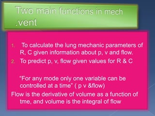
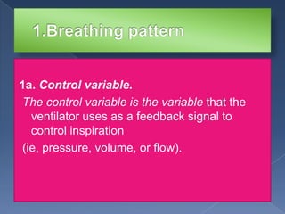
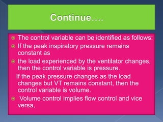
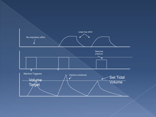
![Volume control implies that the ventilator
determines the
tidal volume [VT], whereas in a spontaneous
breath the
patient determines the VT.
](https://image.slidesharecdn.com/ventilatormodeclassification-131219000611-phpapp02/85/Ventilator-mode-classification-17-320.jpg)
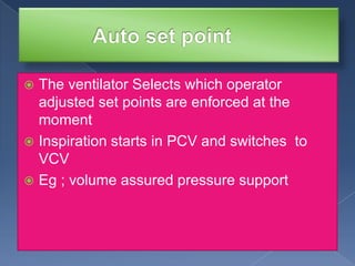
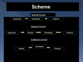
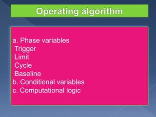
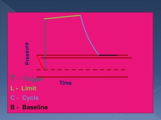
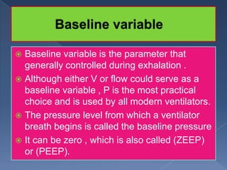


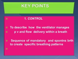
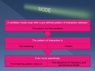
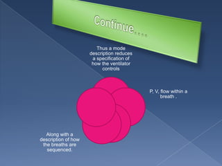
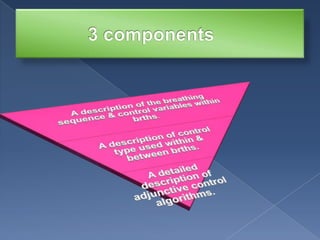
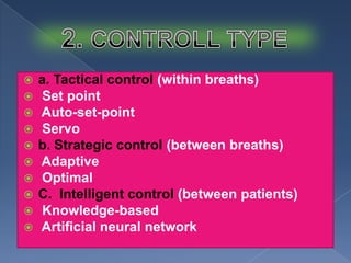
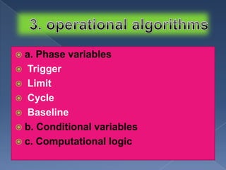
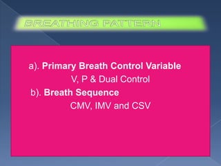
1. A ventilator mode describes how the ventilator controls pressure (P), volume (V), and flow within each breath through a primary control variable (V, P, or dual) and how mandatory and spontaneous breaths are sequenced (CMV, IMV, CSV). 2. Control types describe the ventilator's feedback control and include tactical (within breath), strategic (between breaths), and intelligent (between patients) control. 3. Phase variables like trigger, limit, cycle, and baseline determine the beginning, sustaining and ending of each breath phase.


![Dual controlled modes of mechanical ventilation [onarılmış]](https://cdn.slidesharecdn.com/ss_thumbnails/dualcontrolledmodesofmechanicalventilationonarlm-151116121024-lva1-app6891-thumbnail.jpg?width=640&height=640&fit=bounds)


