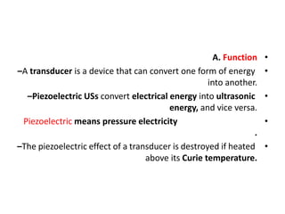
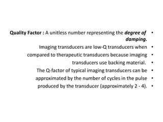
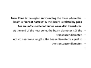
- A transducer is a device that converts one form of energy to another. Piezoelectric ultrasound transducers convert electrical energy to ultrasonic energy and vice versa. Common transducer materials include lead zirconate titanate and polyvinylidene difluoride.
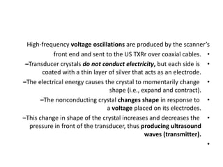
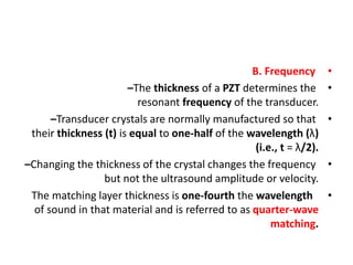
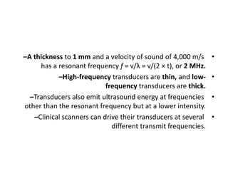
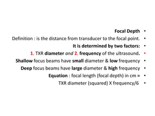
- The thickness of the transducer crystal determines its resonant frequency. Thinner crystals have higher frequencies while thicker crystals have lower frequencies. Transducers can emit ultrasound at frequencies other than the resonant frequency but at lower intensities.
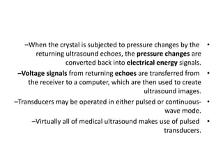
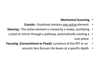
- Transducers can be operated in pulsed or continuous wave mode. Pulsed mode is used for medical ultrasound to produce images. Phased array transducers use variable time delays between transdu

![•
US TXR materials include lead-zirconate-titanate (PZT) ,
plastic polyvinylidene difluoride (PVDF), and the
new monocrystalline transducers.
US TXR materials include lead-zirconate-titanate (PZT) ,
plastic polyvinylidene difluoride (PVDF), and the
new monocrystalline transducers
PZT = P ; for Lead {Lead is a chemical element with the symbol
[Pb] (from the Latin plumbum) and atomic number 82.)
Z ; for Zirconate
T ; for titanate](https://image.slidesharecdn.com/ustransducers2-210327082442/85/Us-transducers-2-3-320.jpg)


![Hepatic doppler us [2]](https://cdn.slidesharecdn.com/ss_thumbnails/hepaticdopplerus2-210813103451-thumbnail.jpg?width=640&height=640&fit=bounds)
![Hepatic doppler us [3]](https://cdn.slidesharecdn.com/ss_thumbnails/hepaticdopplerus3-210813102908-thumbnail.jpg?width=640&height=640&fit=bounds)
![Hepatic dopp us [1]](https://cdn.slidesharecdn.com/ss_thumbnails/hepaticdoppus1-210813101656-thumbnail.jpg?width=640&height=640&fit=bounds)


![Umbilical artery doppler [1]](https://cdn.slidesharecdn.com/ss_thumbnails/umbilicalarterydoppler1-210517112207-thumbnail.jpg?width=640&height=640&fit=bounds)
![Doppler principles [2]](https://cdn.slidesharecdn.com/ss_thumbnails/dopplerprinciples2-210517111747-thumbnail.jpg?width=640&height=640&fit=bounds)
![Doppler principles [1]](https://cdn.slidesharecdn.com/ss_thumbnails/dopplerprinciples1-210517111539-thumbnail.jpg?width=640&height=640&fit=bounds)
![Hepatic doppler us [3]](https://cdn.slidesharecdn.com/ss_thumbnails/hepaticdopplerus3-210517111042-thumbnail.jpg?width=640&height=640&fit=bounds)
![Hepatic doppler us [2]](https://cdn.slidesharecdn.com/ss_thumbnails/hepaticdopplerus2-210517110832-thumbnail.jpg?width=640&height=640&fit=bounds)
![Hepatic dopp us [1]](https://cdn.slidesharecdn.com/ss_thumbnails/hepaticdoppus1-210517110108-thumbnail.jpg?width=640&height=640&fit=bounds)


