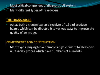
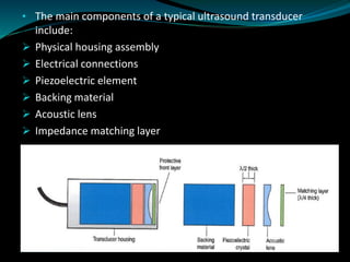
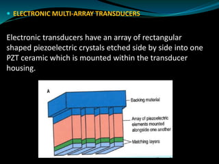
Dr M Kemp
Department of Medical Imaging and Therapeutic Sciences
CPUT
• Most critical component of diagnostic US system
• Many different types of transducers
THE TRANSDUCER
• Act as both a transmitter and receiver of US and produce
beams which can be directed into various ways to improve the
quality of an image.
COMPONENTS AND CONSTRUCTION
• Many types ranging from a simple single element to electronic
multi-array probes which have hundreds of elements.
• The main components of a typical ultrasound transducer
include:
➢ Physical housing assembly
➢ Electrical connections
➢ Piezoelectric element
➢ Backing material
➢ Acoustic lens
➢ Impedance matching layer
Physical housing
• Contains all the individual components including the crystal,
electrodes, matching layer and backing material. Housing
provides the structural support and acts as an electrical and
acoustic insulator.
Electrical connections
• 2 electrical connections are formed on the front and back face
of the crystal by plating a thin film of gold or silver on these
surfaces.
• The electrodes are connected to US machine which generates
the short burst of electrical pulses to excite the crystal and
through the piezoelectric effect generates a pulse of US energy.
Piezoelectric element
• Transducers operate on the piezoelectric effect
• When certain crystalline minerals are subjected to a mechanical
force they become electrically polarized which means they
generate voltages.
• By utilising the piezoelectric property an US transducer can act
both as a transmitter and receiver of ultrasound.
• In transmission mode>short burst of electric energy generated
by US scanner is sent to the transducer generating an US pulse of
energy>reflected US echoes returning to the transducer face are
detected>causing mechanical vibrations which are converted in
electrical voltages>electrical signals are processed by US
machine to form an image
• The ability of a material to generate an electrical charge in
response to applied pressure. When a PZT material is compressed
a potential difference is generated across opposite faces – the one
side becomes positive, the other negative . If electric field is
applied across the crystal it changes its shape.
• Materials which convert sound into electricity ( and vice versa) are
called piezoelectric or ferroelectric.
• Piezoelectric materials are crystalline materials composed of
dipolar molecules which are +ve at one end and –ve at the other .
PIEZOELECTRIC EFFECT VIDEO: https://youtu.be/YEJ2qryXcIQ
 Piezoelectric element is made of man-made ceramics such as lead
zirconate titanate (PZT) which is highly sensitive and easily changes
shape.
 Operating frequency of transducer is dependent upon the thickness
of the crystal.
 For maximum efficiency the crystal should operate at its resonant
frequency>occurs when the thickness of the crystal corresponds to
half a wavelength (λ/2).
 Typical diagnostic US elements are between 0.2 and 1mm thick.
 A transducer operating at a resonant frequency of
2 MHz would have a thickness around 1mm, higher frequency of
7.5 MHz would have thickness of 0.3mm.
 Backing material
When a short burst or pulse of electricity is applied to a crystal it
causes it to vibrate in all directions. The main vibrations come
from the front and back faces of the crystal. Only interest is the
vibrations off the front face of transducer>damping/backing
material is used to eliminate the vibrations from the back face
and control the length of vibrations from the front face.
 Without the backing material a longer pulse of US is
generated by a short burst of electricity as the crystal
continues to vibrate. Attaching a backing material dampens
the vibrations and generates a shorter US pulse. The length of
an US pulse is known as the spatial pulse length (SPL).
 Acoustic lens
The purpose of the acoustic lens is to improve the image resolution by
reducing the beam width of the transducer. Beam width determines
the lateral resolution >ability to resolve structures across or
perpendicular to the beam axis.
 Impedance matching layers
➢ Layer is sandwiched between the piezoelectric crystal and the
patient and is an important factor that effects the sensitivity of the
transducer i.e. ability of the US system to detect small reflected
echoes.
➢ Matching layer typically has an acoustic impedance value halfway
between that of the crystal and soft tissue>resulting in more
transmitted energy entering the patient and improvement of signal
strength of the returning echoes.
➢ More than 1 layer can be used, constructed to be one quarter
wavelength thick (λ/4).
 ELECTRONIC MULTI-ARRAY TRANSDUCERS
Electronic transducers have an array of rectangular
shaped piezoelectric crystals etched side by side into one
PZT ceramic which is mounted within the transducer
housing.
 There are between 128-256 elements across the face of these
transducers which are individually connected through one of the
US machine ports.
 US IMAGE FORMATION
➢ US images are not created by firing all the elements in an
electronic array transducer at the same time.
➢ They are formed by transmitting a series of small narrow beams
along the transducer face which are directed along adjacent
paths through the patient to generate one cross-sectional
image.
➢ Electronic transducers form an image by using small groups of
elements (5-10) to produce a narrow US beam which forms a
scan line.
➢ The US machine can rapidly sequentially sweep the position of
this beam across the face of the transducer to produce a cross-
sectional image
 ELECTRONIC BEAM FOCUSING AND STEERING
➢ The US beam generated from electronic array transducers are
formed by using groups of elements.
➢ These elements create small wavelets that interact with each
other to form an overall US beam with a characteristic
waveform.
Electronic beam focussing
➢ Focusing the US improves the image quality by making the beam
thinner within the focal zone.
➢ Electronic transducers focus the beam by introducing a series of
time delays across a group of elements which are to be excited.
 Consider a group of 9 elements which require a beam to be
focused at a depth A. To create a beam which is focused at depth
A requires all the wavelets created by each individual element to
converge i.e. to arrive at the desired focal point at the same time.
The shortest distance is path A, longest is path B. To ensure that
all wavelets arrive at the same point at the same time, the US
machine through the beam former introduces a set of time delays
across the individual elements.
 ELECTRONIC BEAM STEERING
➢ US beam can also be steered by introducing a set of sequence of
time delays to the transducer pulses across a group of individual
elements.
TYPES OF ELECTRONIC ARRAY TRANSDUCERS
 Linear array
 Curvilinear (or sector) array
 Phased array
 Linear array
➢ This type of array is made of between 128-256 elements in a
row and produces parallel scan lines which are transmitted
perpendicular to the transducer face resulting in a rectangular
FOV.
➢ These transducers are used to image superficial structures and
vessels and operate at frequencies greater than 4 MHz.
 Curvilinear array
➢ Similar to linear but the face is curved which provides a wide
FOV which diverges with depth.
➢ These transducers operate at a lower frequency at
approximately 3.5 MHz and are suited to image deep
structures.
 Phased array
➢ These transducers are physically smaller than the linear and
curvilinear and provides a wide FOV from a small transducer
contact area (footprint).
➢ This type of array is typically utilised in cardiac application.
➢ These small transducers can easily fit between the ribs or
underneath the ribcage to obtain an image of the heart.

Transducers 2020

  • 1.
    Dr M Kemp Departmentof Medical Imaging and Therapeutic Sciences CPUT
  • 2.
    • Most criticalcomponent of diagnostic US system • Many different types of transducers THE TRANSDUCER • Act as both a transmitter and receiver of US and produce beams which can be directed into various ways to improve the quality of an image. COMPONENTS AND CONSTRUCTION • Many types ranging from a simple single element to electronic multi-array probes which have hundreds of elements.
  • 3.
    • The maincomponents of a typical ultrasound transducer include: ➢ Physical housing assembly ➢ Electrical connections ➢ Piezoelectric element ➢ Backing material ➢ Acoustic lens ➢ Impedance matching layer
  • 4.
    Physical housing • Containsall the individual components including the crystal, electrodes, matching layer and backing material. Housing provides the structural support and acts as an electrical and acoustic insulator. Electrical connections • 2 electrical connections are formed on the front and back face of the crystal by plating a thin film of gold or silver on these surfaces. • The electrodes are connected to US machine which generates the short burst of electrical pulses to excite the crystal and through the piezoelectric effect generates a pulse of US energy.
  • 5.
    Piezoelectric element • Transducersoperate on the piezoelectric effect • When certain crystalline minerals are subjected to a mechanical force they become electrically polarized which means they generate voltages. • By utilising the piezoelectric property an US transducer can act both as a transmitter and receiver of ultrasound. • In transmission mode>short burst of electric energy generated by US scanner is sent to the transducer generating an US pulse of energy>reflected US echoes returning to the transducer face are detected>causing mechanical vibrations which are converted in electrical voltages>electrical signals are processed by US machine to form an image
  • 6.
    • The abilityof a material to generate an electrical charge in response to applied pressure. When a PZT material is compressed a potential difference is generated across opposite faces – the one side becomes positive, the other negative . If electric field is applied across the crystal it changes its shape. • Materials which convert sound into electricity ( and vice versa) are called piezoelectric or ferroelectric. • Piezoelectric materials are crystalline materials composed of dipolar molecules which are +ve at one end and –ve at the other .
  • 7.
    PIEZOELECTRIC EFFECT VIDEO:https://youtu.be/YEJ2qryXcIQ
  • 8.
     Piezoelectric elementis made of man-made ceramics such as lead zirconate titanate (PZT) which is highly sensitive and easily changes shape.  Operating frequency of transducer is dependent upon the thickness of the crystal.  For maximum efficiency the crystal should operate at its resonant frequency>occurs when the thickness of the crystal corresponds to half a wavelength (λ/2).  Typical diagnostic US elements are between 0.2 and 1mm thick.  A transducer operating at a resonant frequency of 2 MHz would have a thickness around 1mm, higher frequency of 7.5 MHz would have thickness of 0.3mm.
  • 9.
     Backing material Whena short burst or pulse of electricity is applied to a crystal it causes it to vibrate in all directions. The main vibrations come from the front and back faces of the crystal. Only interest is the vibrations off the front face of transducer>damping/backing material is used to eliminate the vibrations from the back face and control the length of vibrations from the front face.
  • 10.
     Without thebacking material a longer pulse of US is generated by a short burst of electricity as the crystal continues to vibrate. Attaching a backing material dampens the vibrations and generates a shorter US pulse. The length of an US pulse is known as the spatial pulse length (SPL).
  • 11.
     Acoustic lens Thepurpose of the acoustic lens is to improve the image resolution by reducing the beam width of the transducer. Beam width determines the lateral resolution >ability to resolve structures across or perpendicular to the beam axis.  Impedance matching layers ➢ Layer is sandwiched between the piezoelectric crystal and the patient and is an important factor that effects the sensitivity of the transducer i.e. ability of the US system to detect small reflected echoes. ➢ Matching layer typically has an acoustic impedance value halfway between that of the crystal and soft tissue>resulting in more transmitted energy entering the patient and improvement of signal strength of the returning echoes. ➢ More than 1 layer can be used, constructed to be one quarter wavelength thick (λ/4).
  • 12.
     ELECTRONIC MULTI-ARRAYTRANSDUCERS Electronic transducers have an array of rectangular shaped piezoelectric crystals etched side by side into one PZT ceramic which is mounted within the transducer housing.
  • 13.
     There arebetween 128-256 elements across the face of these transducers which are individually connected through one of the US machine ports.
  • 14.
     US IMAGEFORMATION ➢ US images are not created by firing all the elements in an electronic array transducer at the same time. ➢ They are formed by transmitting a series of small narrow beams along the transducer face which are directed along adjacent paths through the patient to generate one cross-sectional image. ➢ Electronic transducers form an image by using small groups of elements (5-10) to produce a narrow US beam which forms a scan line. ➢ The US machine can rapidly sequentially sweep the position of this beam across the face of the transducer to produce a cross- sectional image
  • 16.
     ELECTRONIC BEAMFOCUSING AND STEERING ➢ The US beam generated from electronic array transducers are formed by using groups of elements. ➢ These elements create small wavelets that interact with each other to form an overall US beam with a characteristic waveform. Electronic beam focussing ➢ Focusing the US improves the image quality by making the beam thinner within the focal zone. ➢ Electronic transducers focus the beam by introducing a series of time delays across a group of elements which are to be excited.
  • 17.
     Consider agroup of 9 elements which require a beam to be focused at a depth A. To create a beam which is focused at depth A requires all the wavelets created by each individual element to converge i.e. to arrive at the desired focal point at the same time. The shortest distance is path A, longest is path B. To ensure that all wavelets arrive at the same point at the same time, the US machine through the beam former introduces a set of time delays across the individual elements.
  • 18.
     ELECTRONIC BEAMSTEERING ➢ US beam can also be steered by introducing a set of sequence of time delays to the transducer pulses across a group of individual elements. TYPES OF ELECTRONIC ARRAY TRANSDUCERS  Linear array  Curvilinear (or sector) array  Phased array
  • 20.
     Linear array ➢This type of array is made of between 128-256 elements in a row and produces parallel scan lines which are transmitted perpendicular to the transducer face resulting in a rectangular FOV. ➢ These transducers are used to image superficial structures and vessels and operate at frequencies greater than 4 MHz.  Curvilinear array ➢ Similar to linear but the face is curved which provides a wide FOV which diverges with depth. ➢ These transducers operate at a lower frequency at approximately 3.5 MHz and are suited to image deep structures.
  • 21.
     Phased array ➢These transducers are physically smaller than the linear and curvilinear and provides a wide FOV from a small transducer contact area (footprint). ➢ This type of array is typically utilised in cardiac application. ➢ These small transducers can easily fit between the ribs or underneath the ribcage to obtain an image of the heart.