Download to read offline
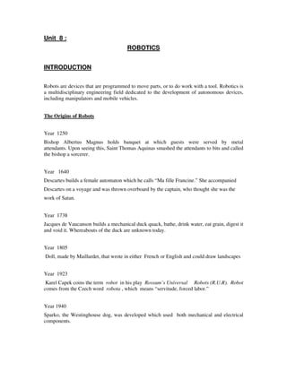
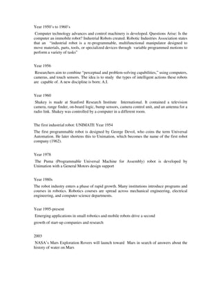
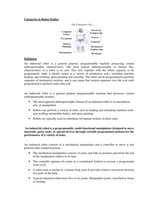


1. Robots are programmable devices that can move parts or tools to perform work. Robotics is a multidisciplinary field focused on developing autonomous devices like manipulators and mobile vehicles. 2. The origins of robots date back to the 13th century, with developments like mechanical attendants and automations throughout history. Modern robotics emerged in the 1950s-60s with advances in computer technology and control systems. 3. There are different categories and applications of robots including industrial robots that perform tasks like welding and assembly, assistive robots that help people with disabilities, and exploratory robots used in hazardous environments.