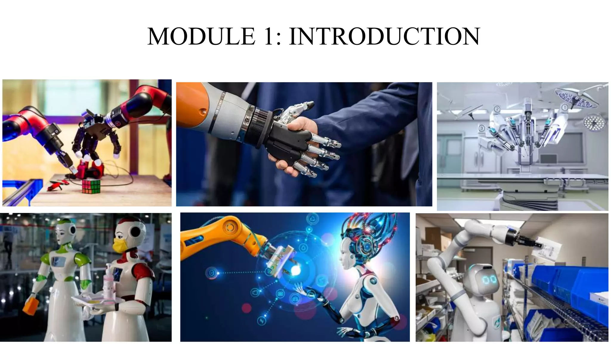
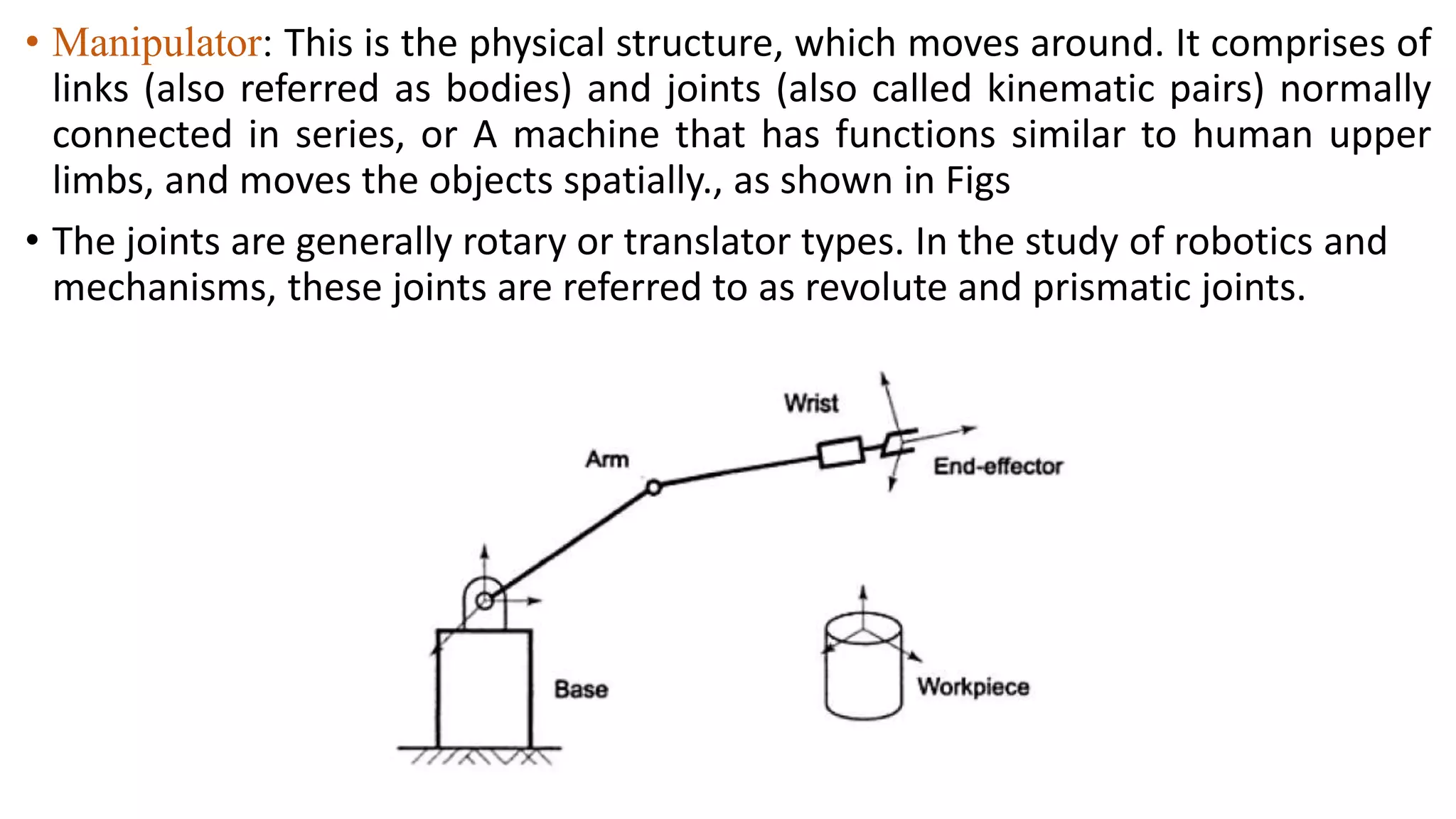
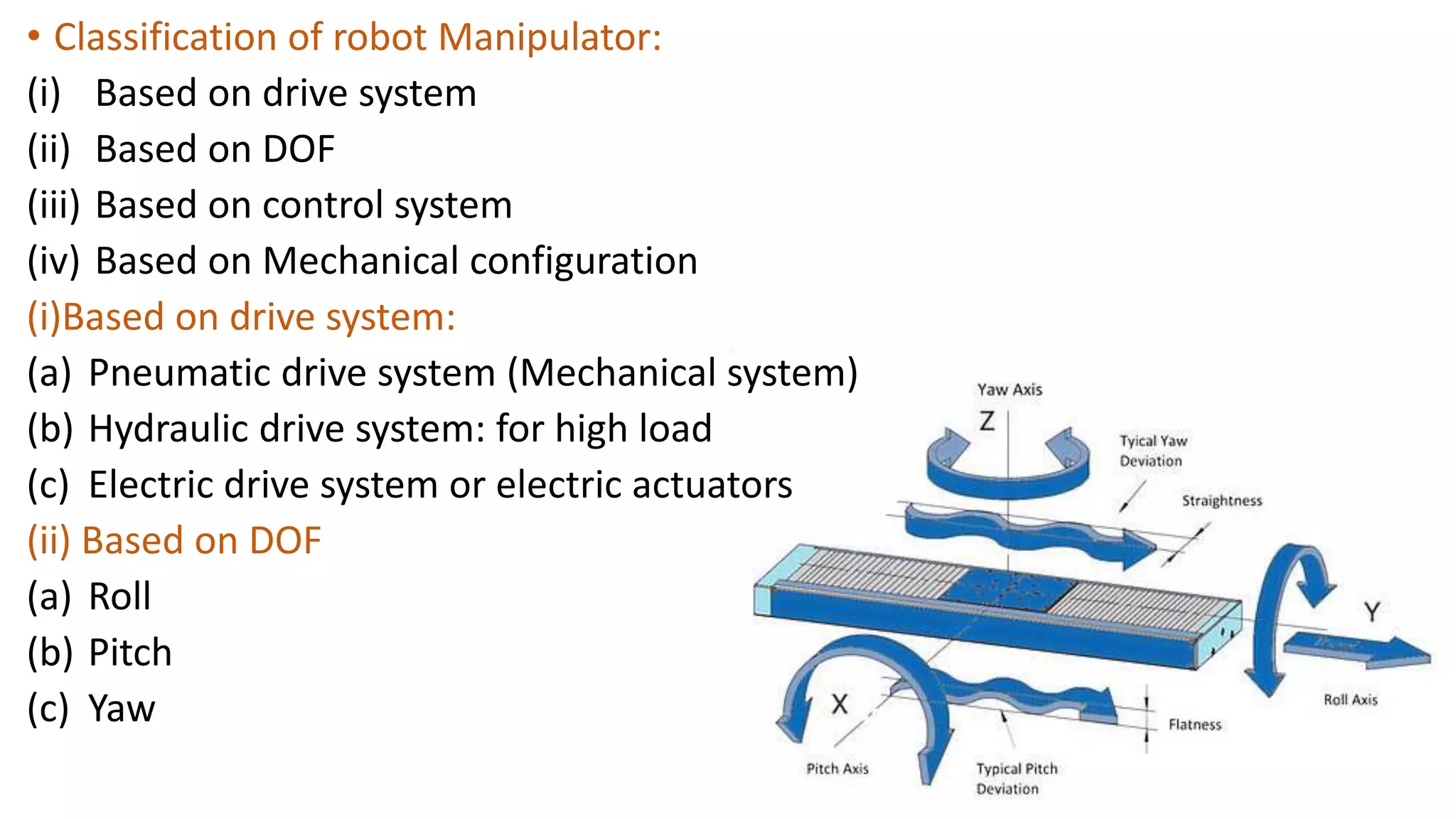
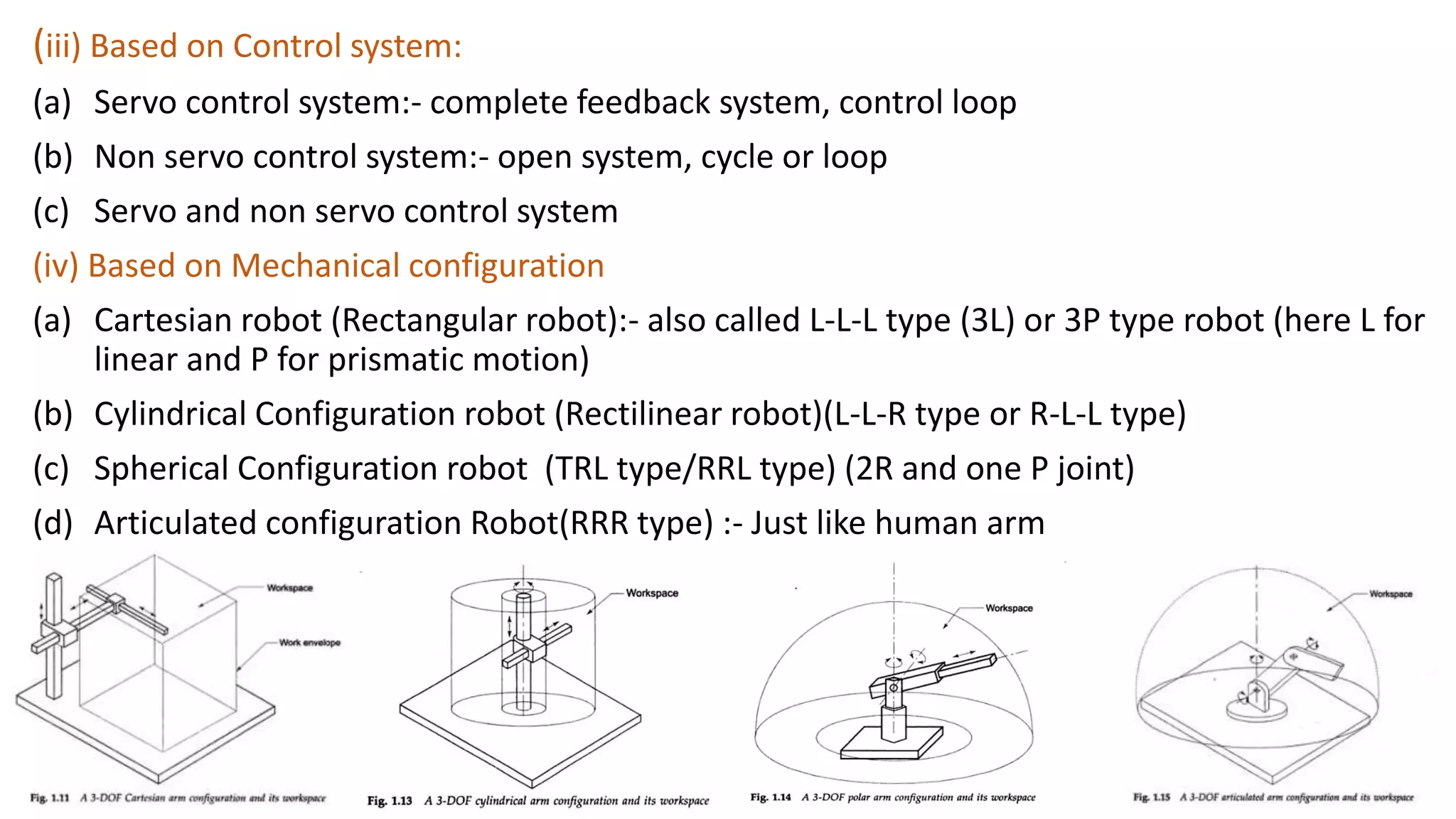
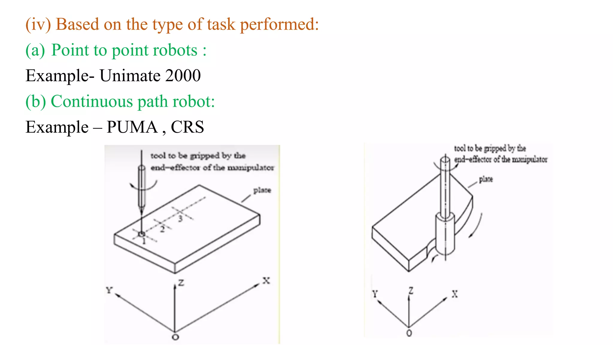
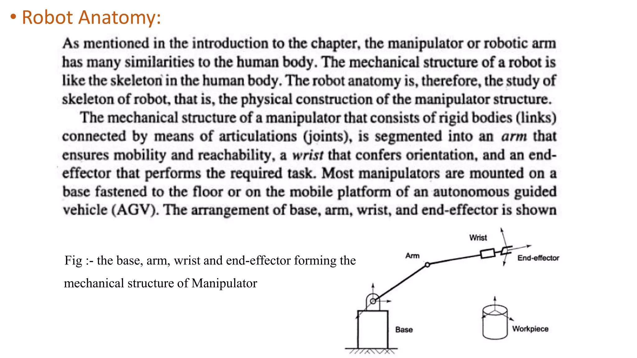
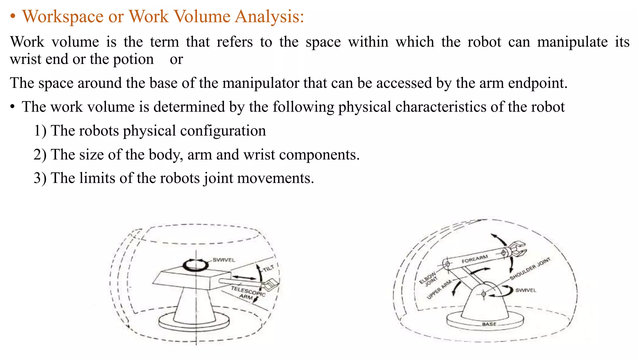
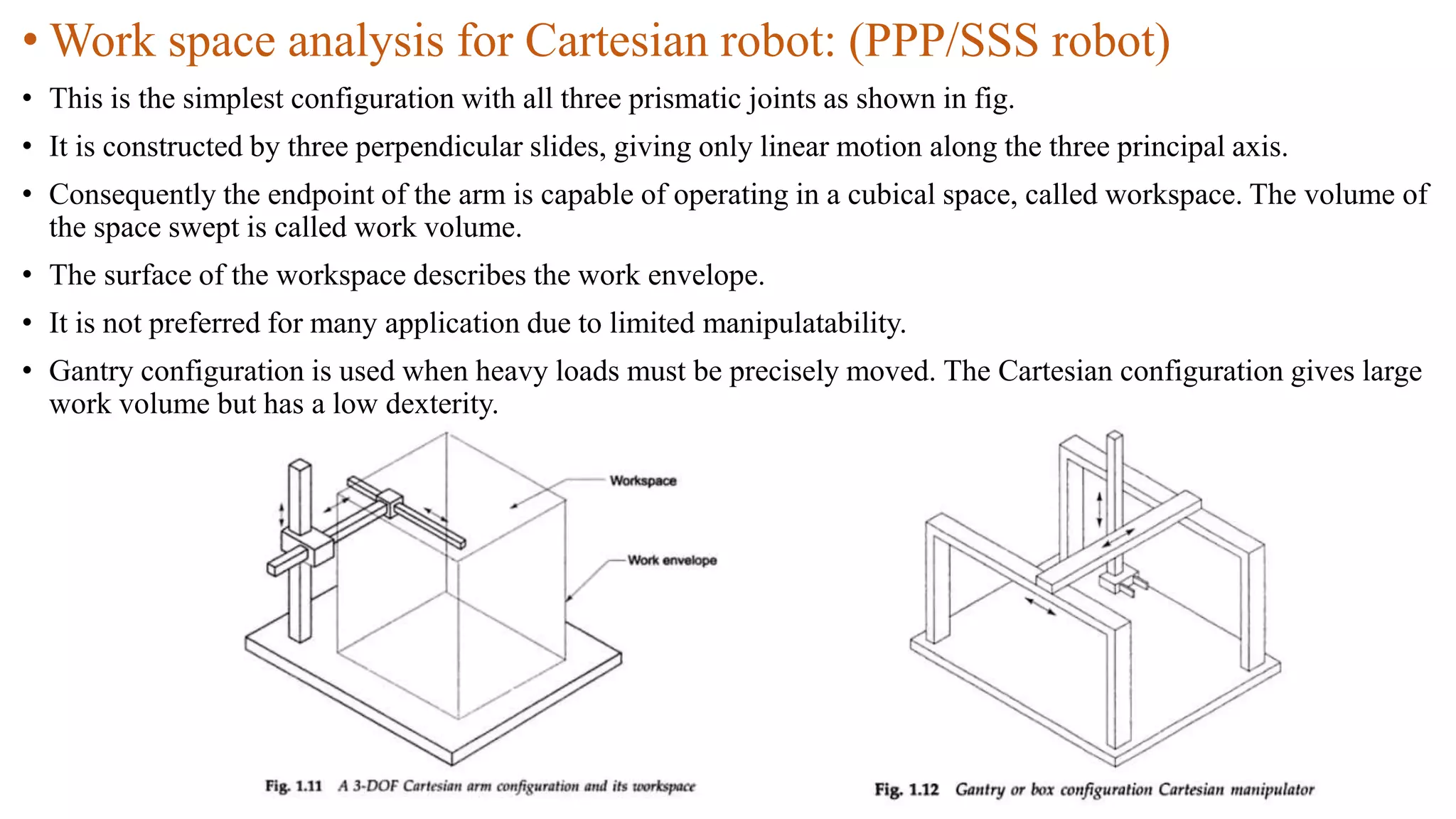
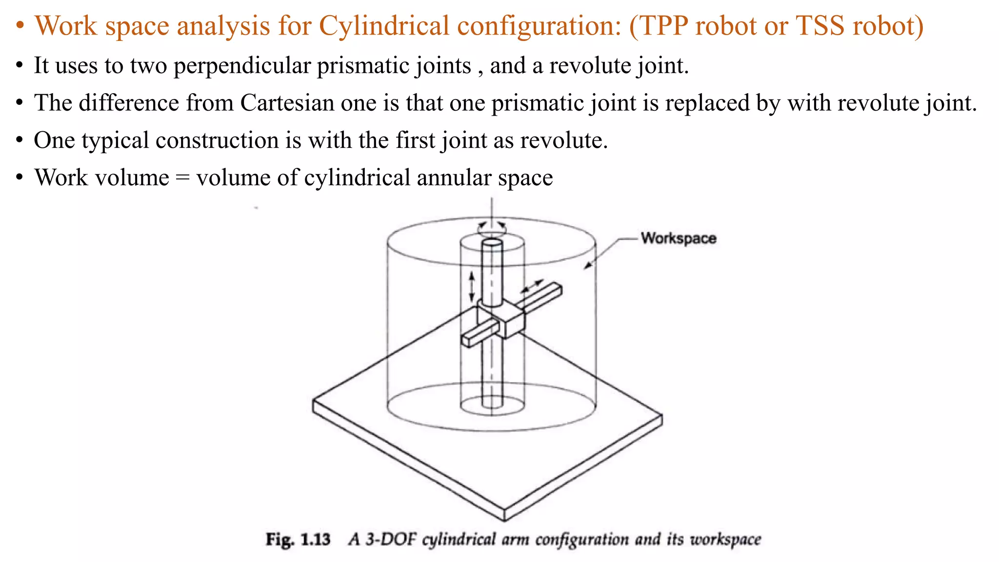
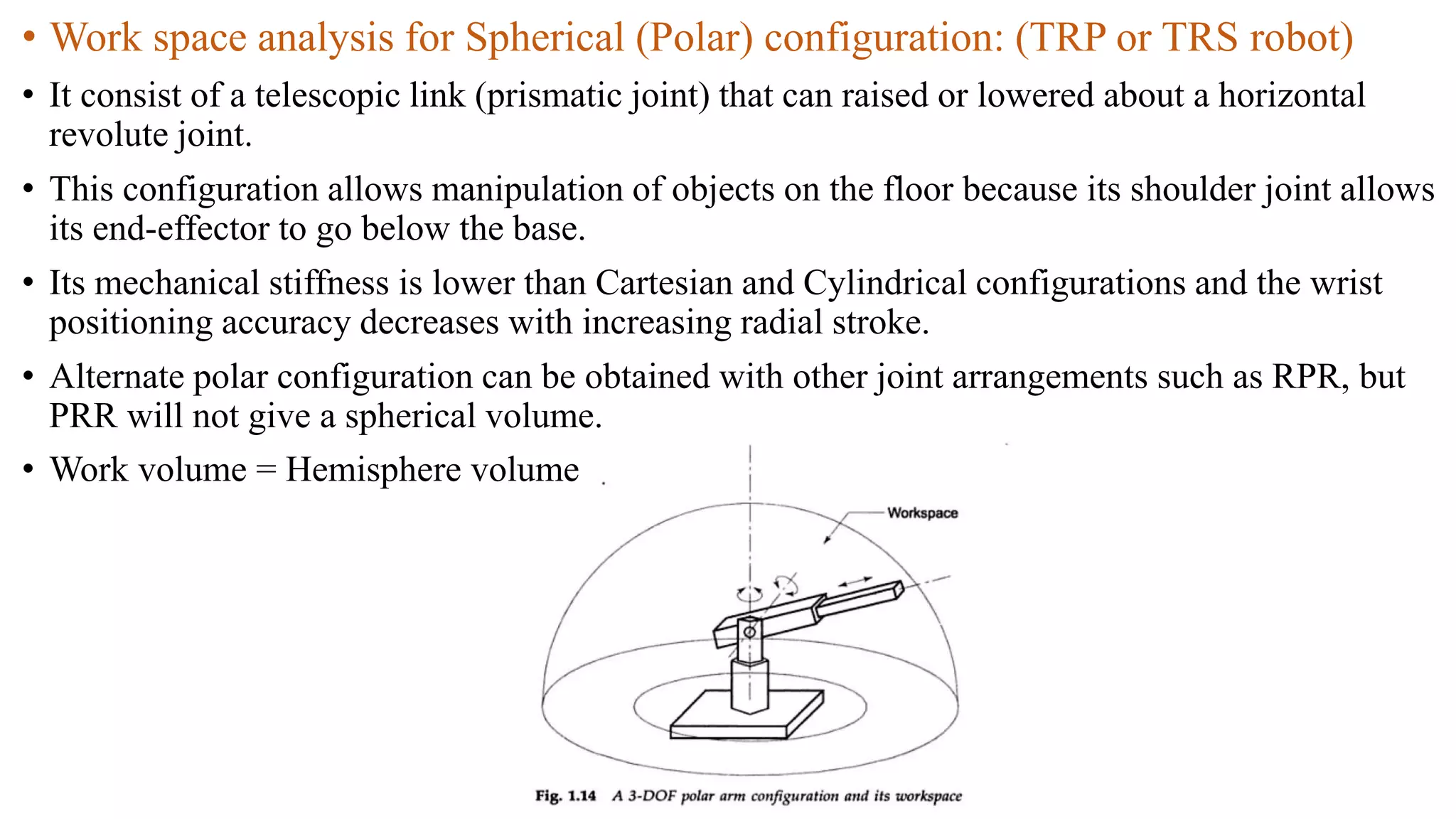
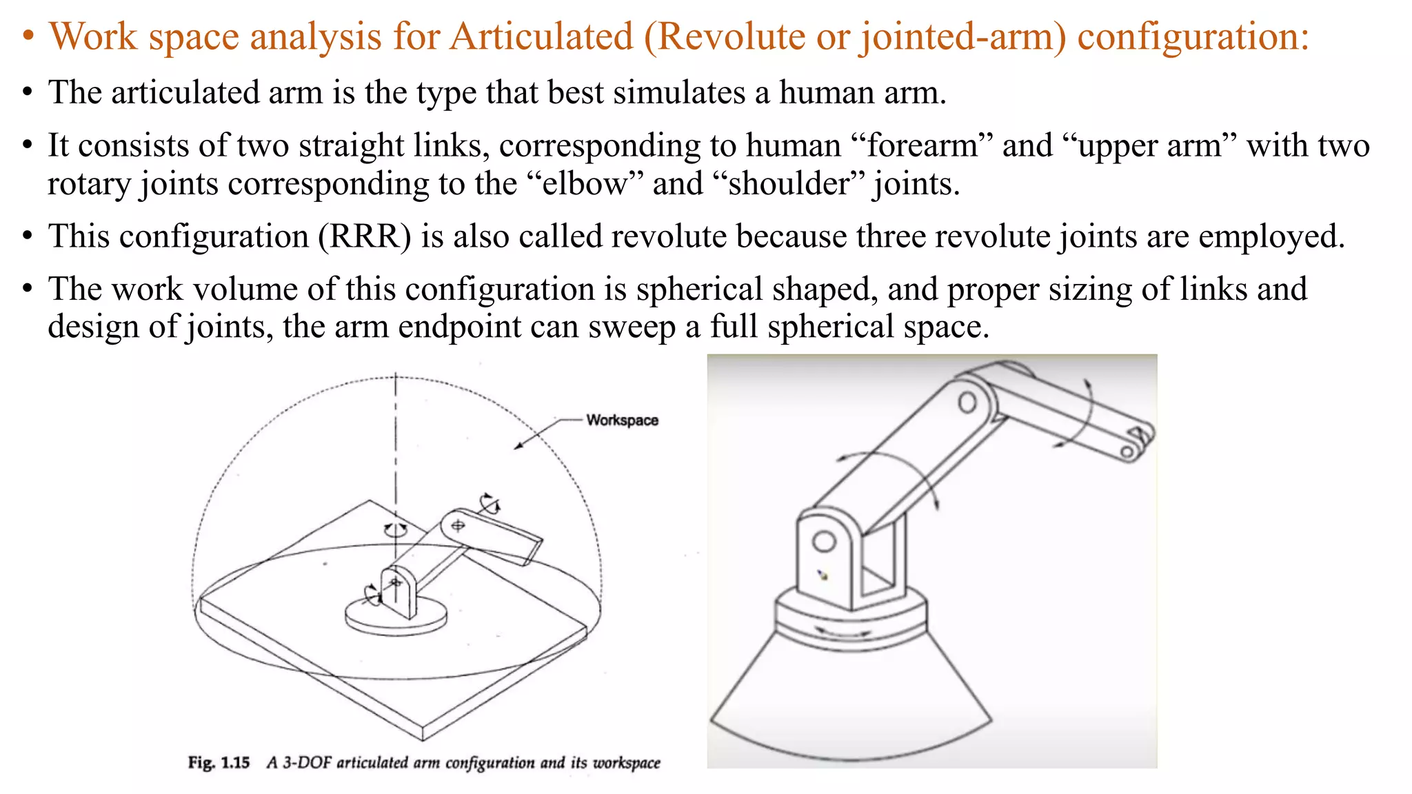
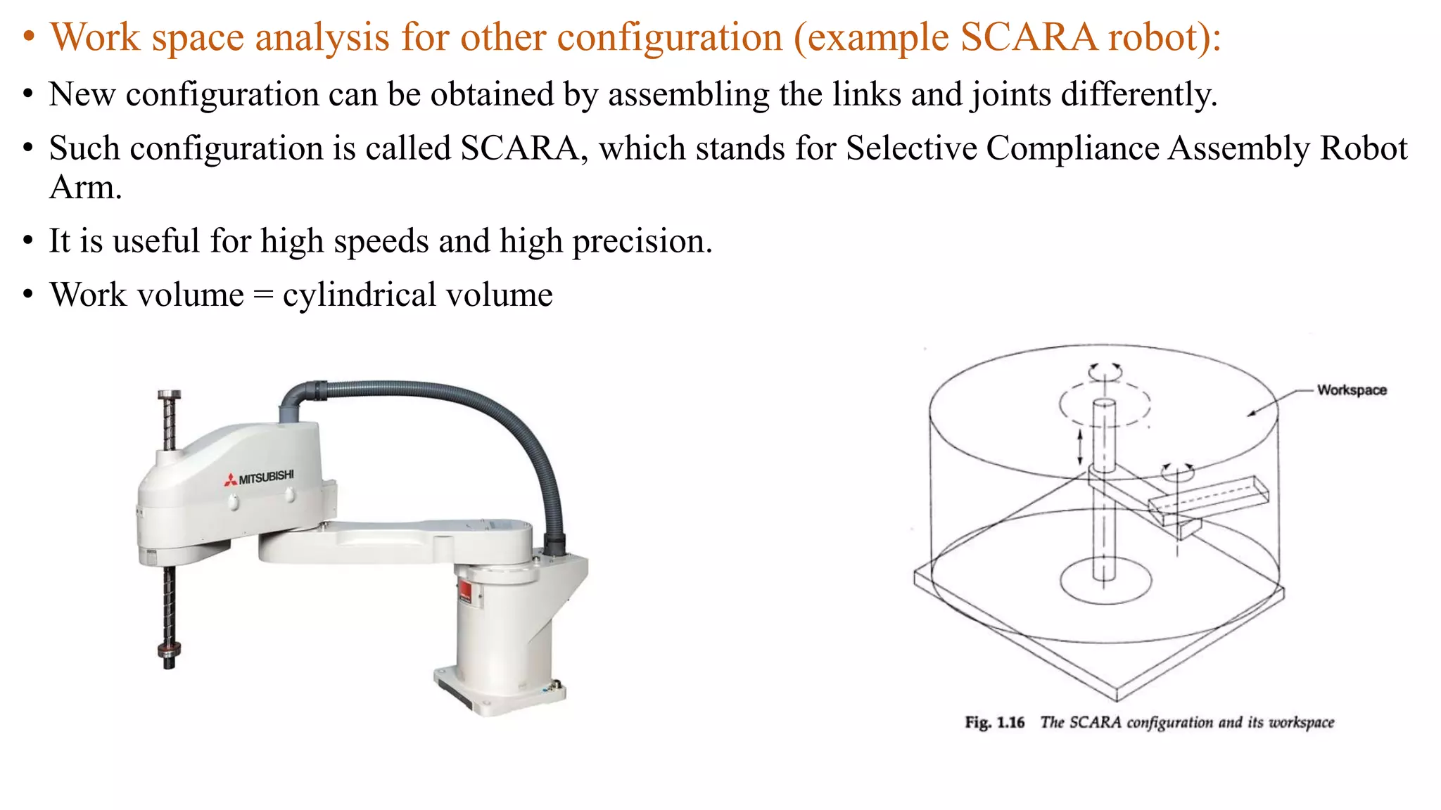
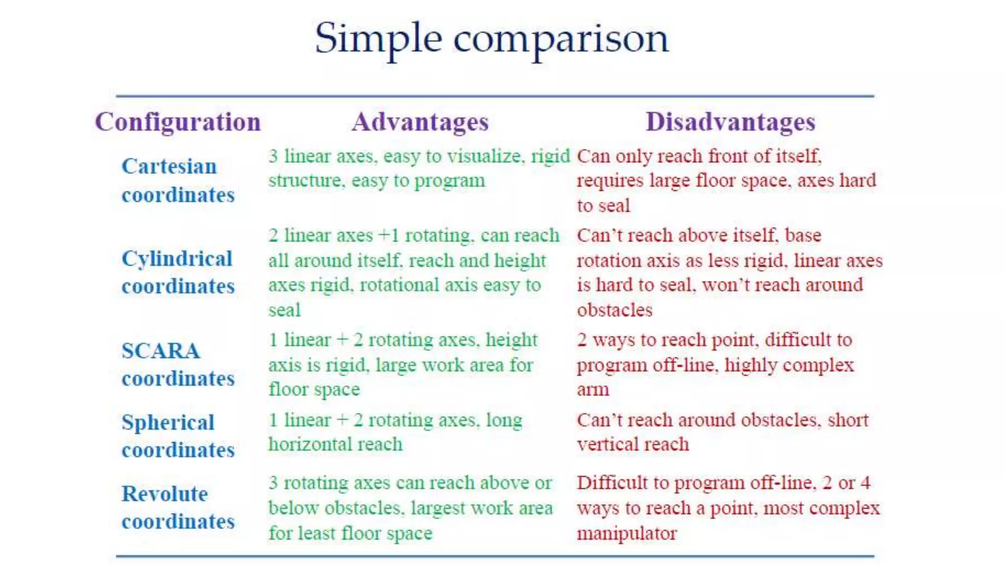
2. • Introduction to robots and robotics
A few questions
• What is a robot?
• What is robotics?
• Why do we study robotics?
• How can we teach a robot to perform a particular task?
and so on
3. Definition
• The term robot has come from the Czech word “robota” which means
forced or slave laborer.
• In 1921, Karel Capek, Czech playwright, used the term robot first in his
drama named Rossum’s Universal Robots (R.U.R)
• Robotics :
it is a science which deals with the issues related to design, manufactruing,
usages of robot.
In 1942, the term: robotics was introduced by Issac Asimov in his story
named Runaround.
In robotics we use the fundamentals of physics, Mathematics, Mechanical
engineering, Electronics engineering, Electrical Engg., Computer science,
and others
4. Motivation:
To cope with increasing demands of dynamic and competitive market,
modern manufacturing methods should satisfy the following requirements:
Reduced production cost
Increased productivity
Improved product quality
5. • The subject of ‘Robotics’ is extremely relevant in today’s engineering curriculum because of
the robots’ ability to perform tireless dangerous jobs. A robot is meaningful only when it is
meant to relieve a human worker from boring, unpleasant, hazardous, or too precise jobs.
• A robot is formally defined by the International Standard of organization (ISO) as a
reprogrammable, multifunctional manipulator designed to move material, parts, tools, or
specialized devices through variable programmed motions for the performance of a variety of
tasks.
• There exist several other definitions too given by other societies, e.g., by the Robotics
Institute of America (RIA), The Japan Industrial Robot Association (JIRA), British Robot
Association (BRA), and others. All definitions have two points in common. They are
‘reprogramability’ and ‘multifunctionality’ of robots.
• In simple word robot definition is “A robot is a software controlled mechanical device that
uses sensors to guide one or more of end effectors through programmed motions in a
workspace in order to manipulate physical objects.
• Note :- CNC machine is not a robot.
6. • Manipulator: This is the physical structure, which moves around. It comprises of
links (also referred as bodies) and joints (also called kinematic pairs) normally
connected in series, or A machine that has functions similar to human upper
limbs, and moves the objects spatially., as shown in Figs
• The joints are generally rotary or translator types. In the study of robotics and
mechanisms, these joints are referred to as revolute and prismatic joints.
7. • Classification of robot Manipulator:
(i) Based on drive system
(ii) Based on DOF
(iii) Based on control system
(iv) Based on Mechanical configuration
(i)Based on drive system:
(a) Pneumatic drive system (Mechanical system)
(b) Hydraulic drive system: for high load
(c) Electric drive system or electric actuators
(ii) Based on DOF
(a) Roll
(b) Pitch
(c) Yaw
8. (iii) Based on Control system:
(a) Servo control system:- complete feedback system, control loop
(b) Non servo control system:- open system, cycle or loop
(c) Servo and non servo control system
(iv) Based on Mechanical configuration
(a) Cartesian robot (Rectangular robot):- also called L-L-L type (3L) or 3P type robot (here L for
linear and P for prismatic motion)
(b) Cylindrical Configuration robot (Rectilinear robot)(L-L-R type or R-L-L type)
(c) Spherical Configuration robot (TRL type/RRL type) (2R and one P joint)
(d) Articulated configuration Robot(RRR type) :- Just like human arm
9. • End effector: This is the part attached at the end of a robot manipulator.
Hence, the name follows. This is equivalent to the human hand. An end-
effector could be a mechanical hand that manipulates an object or holds it
before they are moved by the robot arm.
• the end-effector is external to the manipulator
and its DOF do not combine with the manipulator’s
DOF, as they do not contribute to manipulatability.
• Different end-effectors can be attached to the end
Of the wrist according to the task to be executed.
These can be grouped into two major categories:
(a) Grippers : are end-effectors to grasp or hold the work piece during the work
cycle.
Application:- Material handling, machine loading-unloading, palletizing and etc
10. • . Grippers can be classified as
1. Mechanical grippers
2. Vacuum or suction cups
3. Magnetic grippers
4. Adhesive grippers
5. Hooks,
6. Scoops, and so forth.
• Tool: for many task performed rather then gripper is tool end-effector.
For example, a cutting tool, a drill, a welding torch, a spray gun or a
screwdriver is the end effector for machining, welding, painting or assembly
task mounted at the wrist end point.
12. • General Classification of Robot:
(i) Based on function
(a) Robots with fixed based (also known as Manipulators) : serial mani. (ex. PUMA, CRS),
parallel mani.(ex. stewart platform), hybrid manipulator
(b) Mobile robots :- wheeled robot, tracked( moved any through terrain) robot, legged robot(2
leg, 3 leg, 4 leg, etc)
(c) Underwater robot
(d) Flying robot (swarm robots: moving in air, water and land)
(ii) Based on size of the robots:
(a) Macro robot(range in meter) (b)Micro robot (1um to 100um)
(c) Nano robot
(iii) Based on application
(a) Entertainment robot (b) medical robot (c) surveillance robot (d) service robot
(e) Assembling handling robot (f) Mining robot (g) space robot (h) security robot
13. (iv) Based on the type of task performed:
(a) Point to point robots :
Example- Unimate 2000
(b) Continuous path robot:
Example – PUMA , CRS
14. (v) Based on the type of controllers:
(a) Non-servo controlled robot: open-loop control system
Example:- Sieko PN-100
Less accurate and less expansive
(b) Servo controlled system :- closed loop control system
Example:- Unimate 2000, PUMA.
More accurate and more expansive
(vi) Based on configuration:
(a) Cartesian coordinate robots (PPP/SSS)
(b) Cylindrical coordinate robots (TPP/TSS)
(c) Polar(spherical) coordinate robots (TRP/TRS)
(d) Articulate/ Revolute coordinate robots (TRR)
15. • Selection criteria of a robot:
(a) Work volume
(b) Cost
(c) Payload
(d) Space area
(e) Accuracy
(f) DOF
(g) Resolution, etc.
• Specification of a robot:
(a) DOF (b) Drive system (c) resolution, Precision, accuracy (d) weight of
the manipulator (e) Payload (f) range and speed of the arms and wrist
(g) control system (h) sensors used (i) Coordinate system (j) Cycle time,
Maximum speed (k) Operating environment (l) teaching and programming
methods.
16. • Robot Anatomy:
Fig :- the base, arm, wrist and end-effector forming the
mechanical structure of Manipulator
17. • Workspace or Work Volume Analysis:
Work volume is the term that refers to the space within which the robot can manipulate its
wrist end or the potion or
The space around the base of the manipulator that can be accessed by the arm endpoint.
• The work volume is determined by the following physical characteristics of the robot
1) The robots physical configuration
2) The size of the body, arm and wrist components.
3) The limits of the robots joint movements.
18. • Work space analysis for Cartesian robot: (PPP/SSS robot)
• This is the simplest configuration with all three prismatic joints as shown in fig.
• It is constructed by three perpendicular slides, giving only linear motion along the three principal axis.
• Consequently the endpoint of the arm is capable of operating in a cubical space, called workspace. The volume of
the space swept is called work volume.
• The surface of the workspace describes the work envelope.
• It is not preferred for many application due to limited manipulatability.
• Gantry configuration is used when heavy loads must be precisely moved. The Cartesian configuration gives large
work volume but has a low dexterity.
19. • Work space analysis for Cylindrical configuration: (TPP robot or TSS robot)
• It uses to two perpendicular prismatic joints , and a revolute joint.
• The difference from Cartesian one is that one prismatic joint is replaced by with revolute joint.
• One typical construction is with the first joint as revolute.
• Work volume = volume of cylindrical annular space
20. • Work space analysis for Spherical (Polar) configuration: (TRP or TRS robot)
• It consist of a telescopic link (prismatic joint) that can raised or lowered about a horizontal
revolute joint.
• This configuration allows manipulation of objects on the floor because its shoulder joint allows
its end-effector to go below the base.
• Its mechanical stiffness is lower than Cartesian and Cylindrical configurations and the wrist
positioning accuracy decreases with increasing radial stroke.
• Alternate polar configuration can be obtained with other joint arrangements such as RPR, but
PRR will not give a spherical volume.
• Work volume = Hemisphere volume
21. • Work space analysis for Articulated (Revolute or jointed-arm) configuration:
• The articulated arm is the type that best simulates a human arm.
• It consists of two straight links, corresponding to human “forearm” and “upper arm” with two
rotary joints corresponding to the “elbow” and “shoulder” joints.
• This configuration (RRR) is also called revolute because three revolute joints are employed.
• The work volume of this configuration is spherical shaped, and proper sizing of links and
design of joints, the arm endpoint can sweep a full spherical space.
22. • Work space analysis for other configuration (example SCARA robot):
• New configuration can be obtained by assembling the links and joints differently.
• Such configuration is called SCARA, which stands for Selective Compliance Assembly Robot
Arm.
• It is useful for high speeds and high precision.
• Work volume = cylindrical volume