This document provides an overview of an introductory lecture on optical communication systems. It covers the following key points in 3 sentences:
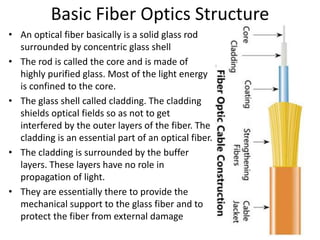
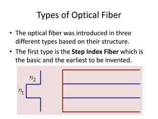
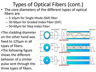
The course will introduce light propagation in optical fibers, optical sources and receivers, signal losses and distortions, designing optical links, integrated optics, and wavelength division multiplexing. The history of communications and how optical fibers fit within the electromagnetic spectrum is discussed. Different types of optical fibers including step index, graded index, and single mode fibers and how they propagate light are described.