SlideShare a Scribd company logo
By: Mr. Ashenafi B. (M.Sc.)
Introductionto CAD
Arba Minch University
Sawla Campus (AMU-SC)
Electromechanical Department
Design-Manufacturing Process
Old (before computer era)
Sketch with
pencils
Engineering Drawing
with pencils
Manufacturing
Sketch
http://www.buzzle.com/articles/leonardo-da-vinci-
inventions.html
http://youtu.be/Rog5i2n1QVs
Eng. Drawing- http://modelenginenews.org/cardfile/m42.h
Eng. Drawing -Part
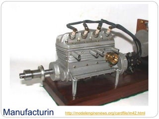
Manufacturin http://modelenginenews.org/cardfile/m42.html
Now…. with
computer
CAD (Solid
Modeling)
Engineerin
g Drawing
Manufacturin
g
CAA (Computer
Aided Analysis)
CAM (Computer
Aided
Manufacturing)
/Direct
Manufacturing
CAD is a starting point of everything!
Check, http://en.wikipedia.org/wiki/Computer-
http://www.cob.unt.edu/slides/Peak/old%205130/Class%2010/Animat
Computer-Aided Engineering (CAE)
 Use of computer systems
to analyze CAD geometry.
 Allows designer to
simulate and study how
the product will behave,
allowing for optimization.
 Finite-element method
(FEM)
 Divides model into
interconnected elements
 Solves continuous field
problems.
http://cadcamfunda.com.p.in.hostingprod.com/cadcam_softwares
Computer-Aided Manufacturing (CAM)
 Use of computer systems to plan, manage, and
control manufacturing operations.
 Direct or indirect
computer interface
with the plant’s
production
resources.
 Numerical control
of machine tools.
 Programming of
robots.
CAM http://blog.iqsdirectory.com/process-equipment/automation-
equipment-lost-jobs-or-efficient-production/
In this course, we will
cover
CAD (Solid
Modeling)
Engineerin
g Drawing
Manufacturin
g
CAA (Computer
Aided Analysis)
CAM (Computer
Aided
Manufacturing)
/Direct
Manufacturing
What is CAD?
 Originally CAD includes any techniques that use
computers in the design process including drafting,
stress analysis and motion analysis.
 But over the last 35 years, CAD has come to refer more
specifically to Computer Aided Design and Drafting.
 CAD program/software is an electronic tool that
enables you to make quick and accurate orthogonal
and 3D drawings with the use of a computer software
packages.
 Computer drawings are neat, clean, highly presentable,
and can be modified easily.
 With CAD, parts or components can be modeled,
visualized, revised, and improved on the computer
screen before any engineering drawings have been
Computer Aided Design (CAD)
Capabilities of CAD
Some of the important capabilities of using CAD
are;
1) Presentations
- You can create fine drawings with
presentation symbols and text styles.
- You can use CAD program to make on
screen presentations.
2) Flexibility in editing
- CAD provides the flexibility to make quick
alterations to drawings
- Some of the editing capabilities are such as;
move or copy drawing elements, enlarge or
reduce size of a drawing, make multiple
copies of a drawing, change units of measure
3) Units and accuracy level
- CAD program allows you to work with
great accuracy. You can also work with
different units of measure, such as
architectural units, engineering units,
scientific units and surveyor units.
4) Storage and access of drawings
- It is quick and convenient to organize
CAD drawings. You can have thousands of
drawings on a computer’s hard disk and
you can open any one of them within
seconds.
Capabilities of CAD (Cont.)
5) Sharing CAD drawings
- The drawings can be shared by a number of
users, allowing them to coordinate projects and
work as a team. This is accomplished by
connecting different computers via a network.
You can also publish your drawings on the
Internet and collaborate CAD projects using a
web site.
6) Project reporting
- The computer can be used to prepare project
reports.
7) Engineering analysis
- There is a separate category of programs
Capabilities of CAD (Cont.)
8) Computer aided manufacturing (CAM)
- CAM is a common method of
manufacturing used by large corporations.
- These systems import CAD drawings into
CAM programs to automate the
manufacturing process.
Capabilities of CAD (Cont.)
CAD Drawbacks
•Initial cost of hardware and software
•Need to re-train staff
•Computers may crash and drawings are lost
•Security of files; files may be hacked
•Need to update software
Fig: Line drawing
plus rendering
CAD Models
 A CAD model is a computer representation
of an object or part.
 It contains all of the design information
including geometry, dimensions,
tolerances, materials and manufacturing
information.
 CAD models replace the paper blueprints
and engineering drawings
 The simplest model used in CAD is a 2D
model. This model is essentially the
computer graphics equivalent to an
orthographic projection.
CAD Models (Cont.)
 A 3D model is the most general model used
in CAD software. This model is equivalent to
an isometric view.
 2 basic types of 3D models are wire frame
and surface models.
 In a 3D wire frame model, only edges of the
object are represented.
 A 3D surface model defines the object in
terms of surfaces such as plates (flat) and
shells (curved) in addition to edges.
Solid Modeling
 The current state of the art in CAD, is the
most sophisticated method of
representing an object.
 Unlike wire frame or surface models, a
solids model represents an object in the
virtual environment just as it exists in
reality, having volume as well as surfaces
and edges. In this way, the interior of the
object is represented in the model as well
as the outer surfaces.
Use of solid models
 Can be used for stress analysis, heat
transfer analysis, fluid flow analysis, and
computer aided manufacturing.
 In the manufacturing process, to
automatically generate machine tool paths to
machine an object.
 To simulate the removal of material from an
initial block of material on the computer
 Can be linked to Computer Numerical
Control (CNC) machine to carry out the
removal of material automatically allowing
many identical parts to be machined based
directly on the solid models.
CAD Process
 Two types of activities: synthesis and
analysis.
 Synthesis is largely qualitative and
hard to capture on computer.
 Analysis can be greatly enhanced with
computers
 Once analysis is complete, design
evaluation- rapid prototyping
 Software packages for design
optimization
Components of CAD/CAM/CAE
Systems
 Major component is
hardware and software
allowing shape
manipulation:
 Hardware includes graphic
devices and their peripherals
for input and output
operations.
 Software includes program
packages that manipulate or
analyze shapes according to
user interaction.
Hardware Components
 Graphic device is composed of a display
processing unit, a display device, and one
or more input devices
 Input devices:
 Mouse
 Space ball
 Data tablet with a puck or stylus
 Keyboard
 Output Devices:
 Plotters
 Color laser printers
Software Components
 CAD software allows the designer
to create and manipulate a shape
interactively and store it.
 CAM software plans, manages and
controls the operations of a
manufacturing site
 CAE software analyzes design
geometry, allowing designer to
study product behavior.
Rapid Prototyping
 Layer by layer fabrication of
3D physical models from
CAD.
 Fast and inexpensive
alternative for producing
prototypes and functional
models.
 Build parts in thin layers.
 Minimum operation time;
typically runs unattended.
Rapid Prototyping
has surgical
applications
 In addition to providing 3D visualization for
digitally rendered items, it can be used to test
the efficiency of a part/product design before
manufacturing in large quantities.
Rapid Prototyping Cycle
CAD software
• AutoCAD, SolidWorks, Pro/Engineer,
CATIA, ……
• Which one is the best?
Depends what you want.
• In this course, we are reliant on AutoCAD
software.
Introduction to AutoCAD
AutoC
AD
Cont.
 AutoCAD is an abbreviation stands for Automated
Computer Aided Design/ Drawing /Drafting which is
an application software that designers (Engineers &
Architects) use in their daily design activities and it by
far, helps in reducing the bulk of work to be done, had
the design been with ruler and pencil.
The use of CAD process provides enhanced graphics
capabilities which allows any designer to:
 Conceptualize his ideas
 Modify the design very easily
 Perform animation
 Make design calculations
 Use colures, fonts and other aesthetic features
Advantage of AutoCAD
 AutoCAD enhances the productivity and
quality of designs.
 Drawings get prepared in relatively
shorter duration.
 Reduced the manpower requirement .
 AutoCAD software is cost effective and
highly affordable.
 Designs can be drawn with greater
accuracy.
 Facilitates easy modification and revision
I. Drawing Area: To provide space to prepare a drawing.
II. Menu Area: To allow the entry of various commands for
preparing the drawings.
III. Command Area: It consists number of dialog boxes which can
be utilized for preparing the drawings.
IV. Tool Area: To allow selection of various options for the drawing.
AutoCAD package utilize four areas on the screen:
AutoCAD Window
HOW AutoCAD WORKS
 There is a co-ordinate system used in
AutoCAD.
 Every drawing shows its co-ordinate.
 There is so many commands like copy,
move ,rotate ,mirror in 2D, array , offset,
chamfer, fillet & more.
 Different types of drawing can be made in
the same time by using a command that is
LAYER.
 Using line , arc , circle , rectangle , ellipse &
Co-Ordinate System
 Every thing that we draw in AutoCAD is exact.
 All object drawn on screen is based on simple X-Y
coordinate system.
 In AutoCAD it is known as world co-ordinate system (WCS).
 We are drawing a line, so we have two points A(-10,-4) and
B(9,6). As shown in figure.
UCS vs WCS
 The AutoCAD world is 3 dimensional. However, if
we want to draw a 2d object, such as a plan or a
section, we will use only 2 dimensions (x and y).
 WCS (world coordinate system) is the imaginary
plane that is parallel to the ground. It is the default
coordinate system.
 Modifications made to the World Coordinate
System (WCS) result in a User Coordinate System
(UCS). It is the plane that you work on. It enables
the user to draw 3 dimensional objects.
 To create a new UCS, type ‘ucs’ on the command
window, then say New and specify 3 points on your
Angle Measurement in AutoCAD
 Positive degrees are measured counter clockwise
starting from 3 o’clock that means from positive x-
axis. Clockwise angle measurement results negative
degree.
Way to Provide Commands
1. Keystrokes/ Using Key
Board
2. Drop Down Menu
3. Shortcut Icons
Ways of Inserting Point Commands
1. Absolute Co-ordinate Entry
X,Y
2. Relative Co-ordinate Entry
@X,Y
3. Polar Co-ordinate Entry
@D<A
Basic Drawing and Modifying Commands
Example-1
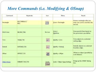
More Commands (i.e. Modifying & OSnap)
Example-2
Assignment-1
Assignment-2
Selecting Objects in AutoCAD
Important Modifying Commands
Example-3
Power Modifying Commands
Example-3
Assignment-2
Layers, Dimensioning, Text & Scale
Example-4
Direct Distance Entry & Object Tracking
 Direct Tracking (ORTHO): Direct distance
entry. Constrains cursor movement to the
horizontal or vertical.
 Polar Tracking (POLAR): Polar distance
entry.
 Object Snap Tracking.
Polyline Commands & Layouts
Hatching-Filling Areas
Three-Dimensioning (3D)
Drawing
Example-1
Example-2
Example-3
Example-4
Example-5
Assignment-4
End!!

More Related Content

Similar to AutoCAD Tutorial AB.pptx

Nx file
Nx fileNx file
Nx file
Nx fileNx file
Fundamentals of 3D modeling
Fundamentals of 3D modelingFundamentals of 3D modeling
Fundamentals of 3D modeling
Aniket Joshi
 
AUTOCAD REPORT.pptx
AUTOCAD REPORT.pptxAUTOCAD REPORT.pptx
AUTOCAD REPORT.pptx
harshkumar441190
 
Autocad civil project file
Autocad civil project fileAutocad civil project file
Autocad civil project file
naveen899
 
CAD vs CAE
CAD vs CAECAD vs CAE
CAD vs CAE
Sisubalan Selvan
 
Abhijeet Pombarekar
Abhijeet PombarekarAbhijeet Pombarekar
Abhijeet Pombarekar
Abhijeet Pombarekar
 
Computer aided design and computer aided manufacturing
Computer aided design and computer aided manufacturingComputer aided design and computer aided manufacturing
Computer aided design and computer aided manufacturing
shoaibzaheer1
 
AutoCAD 2D training report
AutoCAD 2D training reportAutoCAD 2D training report
AutoCAD 2D training report
STAY CURIOUS
 
6 weeks software training report
6 weeks software training report    6 weeks software training report
6 weeks software training report
sucha soorma designs
 
Cad cam
Cad camCad cam
Cad cam
Ajay Singh
 
Cad cam report-final (mechanical workshop)
Cad cam report-final (mechanical workshop)Cad cam report-final (mechanical workshop)
Cad cam report-final (mechanical workshop)Parthibanraj Selvaraj
 
CAD/CAM Lecture #1
CAD/CAM Lecture #1CAD/CAM Lecture #1
CAD/CAM Lecture #1
Yugal Kishor Sahu
 
Power point Presentation on AutoCAD And NX software
Power point Presentation on AutoCAD And NX softwarePower point Presentation on AutoCAD And NX software
Power point Presentation on AutoCAD And NX software
VimalJasoliya1
 
Catia v5 presentation report
Catia v5 presentation reportCatia v5 presentation report
Catia v5 presentation report
Munna Kumar
 
Introduction of Computer aided Design
Introduction of Computer aided DesignIntroduction of Computer aided Design
Introduction of Computer aided Design
Muthukumar V
 
Rapid prototyping and tooling
Rapid prototyping and toolingRapid prototyping and tooling
Rapid prototyping and tooling
Thulasikanth Vaddi
 
CADM-Unit 1/INTRODUCTION
CADM-Unit 1/INTRODUCTIONCADM-Unit 1/INTRODUCTION
CADM-Unit 1/INTRODUCTION
gopalkrishnan202
 
Intro to CAD CAM Tools
Intro to CAD CAM ToolsIntro to CAD CAM Tools
Intro to CAD CAM Tools
Abhay Gore
 

Similar to AutoCAD Tutorial AB.pptx (20)

Nx file
Nx fileNx file
Nx file
 
Nx file
Nx fileNx file
Nx file
 
Fundamentals of 3D modeling
Fundamentals of 3D modelingFundamentals of 3D modeling
Fundamentals of 3D modeling
 
AUTOCAD REPORT.pptx
AUTOCAD REPORT.pptxAUTOCAD REPORT.pptx
AUTOCAD REPORT.pptx
 
Autocad civil project file
Autocad civil project fileAutocad civil project file
Autocad civil project file
 
CAD vs CAE
CAD vs CAECAD vs CAE
CAD vs CAE
 
Abhijeet Pombarekar
Abhijeet PombarekarAbhijeet Pombarekar
Abhijeet Pombarekar
 
Computer aided design and computer aided manufacturing
Computer aided design and computer aided manufacturingComputer aided design and computer aided manufacturing
Computer aided design and computer aided manufacturing
 
AutoCAD 2D training report
AutoCAD 2D training reportAutoCAD 2D training report
AutoCAD 2D training report
 
6 weeks software training report
6 weeks software training report    6 weeks software training report
6 weeks software training report
 
Cad cam
Cad camCad cam
Cad cam
 
Cad cam report-final (mechanical workshop)
Cad cam report-final (mechanical workshop)Cad cam report-final (mechanical workshop)
Cad cam report-final (mechanical workshop)
 
CAD/CAM Lecture #1
CAD/CAM Lecture #1CAD/CAM Lecture #1
CAD/CAM Lecture #1
 
Power point Presentation on AutoCAD And NX software
Power point Presentation on AutoCAD And NX softwarePower point Presentation on AutoCAD And NX software
Power point Presentation on AutoCAD And NX software
 
Catia v5 presentation report
Catia v5 presentation reportCatia v5 presentation report
Catia v5 presentation report
 
Introduction of Computer aided Design
Introduction of Computer aided DesignIntroduction of Computer aided Design
Introduction of Computer aided Design
 
Rapid prototyping and tooling
Rapid prototyping and toolingRapid prototyping and tooling
Rapid prototyping and tooling
 
CADM-Unit 1/INTRODUCTION
CADM-Unit 1/INTRODUCTIONCADM-Unit 1/INTRODUCTION
CADM-Unit 1/INTRODUCTION
 
DOC of Crank shaft
DOC of Crank shaftDOC of Crank shaft
DOC of Crank shaft
 
Intro to CAD CAM Tools
Intro to CAD CAM ToolsIntro to CAD CAM Tools
Intro to CAD CAM Tools
 

Recently uploaded

Expert Accessory Dwelling Unit (ADU) Drafting Services
Expert Accessory Dwelling Unit (ADU) Drafting ServicesExpert Accessory Dwelling Unit (ADU) Drafting Services
Expert Accessory Dwelling Unit (ADU) Drafting Services
ResDraft
 
Between Filth and Fortune- Urban Cattle Foraging Realities by Devi S Nair, An...
Between Filth and Fortune- Urban Cattle Foraging Realities by Devi S Nair, An...Between Filth and Fortune- Urban Cattle Foraging Realities by Devi S Nair, An...
Between Filth and Fortune- Urban Cattle Foraging Realities by Devi S Nair, An...
Mansi Shah
 
Transforming Brand Perception and Boosting Profitability
Transforming Brand Perception and Boosting ProfitabilityTransforming Brand Perception and Boosting Profitability
Transforming Brand Perception and Boosting Profitability
aaryangarg12
 
一比一原版(Bristol毕业证书)布里斯托大学毕业证成绩单如何办理
一比一原版(Bristol毕业证书)布里斯托大学毕业证成绩单如何办理一比一原版(Bristol毕业证书)布里斯托大学毕业证成绩单如何办理
一比一原版(Bristol毕业证书)布里斯托大学毕业证成绩单如何办理
smpc3nvg
 
CA OFFICE office office office _VIEWS.pdf
CA OFFICE office office office _VIEWS.pdfCA OFFICE office office office _VIEWS.pdf
CA OFFICE office office office _VIEWS.pdf
SudhanshuMandlik
 
Top Israeli Products and Brands - Plan it israel.pdf
Top Israeli Products and Brands - Plan it israel.pdfTop Israeli Products and Brands - Plan it israel.pdf
Top Israeli Products and Brands - Plan it israel.pdf
PlanitIsrael
 
Portfolio.pdf
Portfolio.pdfPortfolio.pdf
Portfolio.pdf
garcese
 
Design Thinking Design thinking Design thinking
Design Thinking Design thinking Design thinkingDesign Thinking Design thinking Design thinking
Design Thinking Design thinking Design thinking
cy0krjxt
 
一比一原版(CITY毕业证书)谢菲尔德哈勒姆大学毕业证如何办理
一比一原版(CITY毕业证书)谢菲尔德哈勒姆大学毕业证如何办理一比一原版(CITY毕业证书)谢菲尔德哈勒姆大学毕业证如何办理
一比一原版(CITY毕业证书)谢菲尔德哈勒姆大学毕业证如何办理
9a93xvy
 
PORTFOLIO FABIANA VILLANI ARCHITECTURE.pdf
PORTFOLIO FABIANA VILLANI ARCHITECTURE.pdfPORTFOLIO FABIANA VILLANI ARCHITECTURE.pdf
PORTFOLIO FABIANA VILLANI ARCHITECTURE.pdf
fabianavillanib
 
Design Thinking Design thinking Design thinking
Design Thinking Design thinking Design thinkingDesign Thinking Design thinking Design thinking
Design Thinking Design thinking Design thinking
cy0krjxt
 
20 slides of research movie and artists .pdf
20 slides of research movie and artists .pdf20 slides of research movie and artists .pdf
20 slides of research movie and artists .pdf
ameli25062005
 
一比一原版(UCB毕业证书)伯明翰大学学院毕业证成绩单如何办理
一比一原版(UCB毕业证书)伯明翰大学学院毕业证成绩单如何办理一比一原版(UCB毕业证书)伯明翰大学学院毕业证成绩单如何办理
一比一原版(UCB毕业证书)伯明翰大学学院毕业证成绩单如何办理
h7j5io0
 
一比一原版(NCL毕业证书)纽卡斯尔大学毕业证成绩单如何办理
一比一原版(NCL毕业证书)纽卡斯尔大学毕业证成绩单如何办理一比一原版(NCL毕业证书)纽卡斯尔大学毕业证成绩单如何办理
一比一原版(NCL毕业证书)纽卡斯尔大学毕业证成绩单如何办理
7sd8fier
 
Design Thinking Design thinking Design thinking
Design Thinking Design thinking Design thinkingDesign Thinking Design thinking Design thinking
Design Thinking Design thinking Design thinking
cy0krjxt
 
一比一原版(Bolton毕业证书)博尔顿大学毕业证成绩单如何办理
一比一原版(Bolton毕业证书)博尔顿大学毕业证成绩单如何办理一比一原版(Bolton毕业证书)博尔顿大学毕业证成绩单如何办理
一比一原版(Bolton毕业证书)博尔顿大学毕业证成绩单如何办理
h7j5io0
 
Common Designing Mistakes and How to avoid them
Common Designing Mistakes and How to avoid themCommon Designing Mistakes and How to avoid them
Common Designing Mistakes and How to avoid them
madhavlakhanpal29
 
一比一原版(RHUL毕业证书)伦敦大学皇家霍洛威学院毕业证如何办理
一比一原版(RHUL毕业证书)伦敦大学皇家霍洛威学院毕业证如何办理一比一原版(RHUL毕业证书)伦敦大学皇家霍洛威学院毕业证如何办理
一比一原版(RHUL毕业证书)伦敦大学皇家霍洛威学院毕业证如何办理
9a93xvy
 
National-Learning-Camp 2024 deped....pptx
National-Learning-Camp 2024 deped....pptxNational-Learning-Camp 2024 deped....pptx
National-Learning-Camp 2024 deped....pptx
AlecAnidul
 
Top 5 Indian Style Modular Kitchen Designs
Top 5 Indian Style Modular Kitchen DesignsTop 5 Indian Style Modular Kitchen Designs
Top 5 Indian Style Modular Kitchen Designs
Finzo Kitchens
 

Recently uploaded (20)

Expert Accessory Dwelling Unit (ADU) Drafting Services
Expert Accessory Dwelling Unit (ADU) Drafting ServicesExpert Accessory Dwelling Unit (ADU) Drafting Services
Expert Accessory Dwelling Unit (ADU) Drafting Services
 
Between Filth and Fortune- Urban Cattle Foraging Realities by Devi S Nair, An...
Between Filth and Fortune- Urban Cattle Foraging Realities by Devi S Nair, An...Between Filth and Fortune- Urban Cattle Foraging Realities by Devi S Nair, An...
Between Filth and Fortune- Urban Cattle Foraging Realities by Devi S Nair, An...
 
Transforming Brand Perception and Boosting Profitability
Transforming Brand Perception and Boosting ProfitabilityTransforming Brand Perception and Boosting Profitability
Transforming Brand Perception and Boosting Profitability
 
一比一原版(Bristol毕业证书)布里斯托大学毕业证成绩单如何办理
一比一原版(Bristol毕业证书)布里斯托大学毕业证成绩单如何办理一比一原版(Bristol毕业证书)布里斯托大学毕业证成绩单如何办理
一比一原版(Bristol毕业证书)布里斯托大学毕业证成绩单如何办理
 
CA OFFICE office office office _VIEWS.pdf
CA OFFICE office office office _VIEWS.pdfCA OFFICE office office office _VIEWS.pdf
CA OFFICE office office office _VIEWS.pdf
 
Top Israeli Products and Brands - Plan it israel.pdf
Top Israeli Products and Brands - Plan it israel.pdfTop Israeli Products and Brands - Plan it israel.pdf
Top Israeli Products and Brands - Plan it israel.pdf
 
Portfolio.pdf
Portfolio.pdfPortfolio.pdf
Portfolio.pdf
 
Design Thinking Design thinking Design thinking
Design Thinking Design thinking Design thinkingDesign Thinking Design thinking Design thinking
Design Thinking Design thinking Design thinking
 
一比一原版(CITY毕业证书)谢菲尔德哈勒姆大学毕业证如何办理
一比一原版(CITY毕业证书)谢菲尔德哈勒姆大学毕业证如何办理一比一原版(CITY毕业证书)谢菲尔德哈勒姆大学毕业证如何办理
一比一原版(CITY毕业证书)谢菲尔德哈勒姆大学毕业证如何办理
 
PORTFOLIO FABIANA VILLANI ARCHITECTURE.pdf
PORTFOLIO FABIANA VILLANI ARCHITECTURE.pdfPORTFOLIO FABIANA VILLANI ARCHITECTURE.pdf
PORTFOLIO FABIANA VILLANI ARCHITECTURE.pdf
 
Design Thinking Design thinking Design thinking
Design Thinking Design thinking Design thinkingDesign Thinking Design thinking Design thinking
Design Thinking Design thinking Design thinking
 
20 slides of research movie and artists .pdf
20 slides of research movie and artists .pdf20 slides of research movie and artists .pdf
20 slides of research movie and artists .pdf
 
一比一原版(UCB毕业证书)伯明翰大学学院毕业证成绩单如何办理
一比一原版(UCB毕业证书)伯明翰大学学院毕业证成绩单如何办理一比一原版(UCB毕业证书)伯明翰大学学院毕业证成绩单如何办理
一比一原版(UCB毕业证书)伯明翰大学学院毕业证成绩单如何办理
 
一比一原版(NCL毕业证书)纽卡斯尔大学毕业证成绩单如何办理
一比一原版(NCL毕业证书)纽卡斯尔大学毕业证成绩单如何办理一比一原版(NCL毕业证书)纽卡斯尔大学毕业证成绩单如何办理
一比一原版(NCL毕业证书)纽卡斯尔大学毕业证成绩单如何办理
 
Design Thinking Design thinking Design thinking
Design Thinking Design thinking Design thinkingDesign Thinking Design thinking Design thinking
Design Thinking Design thinking Design thinking
 
一比一原版(Bolton毕业证书)博尔顿大学毕业证成绩单如何办理
一比一原版(Bolton毕业证书)博尔顿大学毕业证成绩单如何办理一比一原版(Bolton毕业证书)博尔顿大学毕业证成绩单如何办理
一比一原版(Bolton毕业证书)博尔顿大学毕业证成绩单如何办理
 
Common Designing Mistakes and How to avoid them
Common Designing Mistakes and How to avoid themCommon Designing Mistakes and How to avoid them
Common Designing Mistakes and How to avoid them
 
一比一原版(RHUL毕业证书)伦敦大学皇家霍洛威学院毕业证如何办理
一比一原版(RHUL毕业证书)伦敦大学皇家霍洛威学院毕业证如何办理一比一原版(RHUL毕业证书)伦敦大学皇家霍洛威学院毕业证如何办理
一比一原版(RHUL毕业证书)伦敦大学皇家霍洛威学院毕业证如何办理
 
National-Learning-Camp 2024 deped....pptx
National-Learning-Camp 2024 deped....pptxNational-Learning-Camp 2024 deped....pptx
National-Learning-Camp 2024 deped....pptx
 
Top 5 Indian Style Modular Kitchen Designs
Top 5 Indian Style Modular Kitchen DesignsTop 5 Indian Style Modular Kitchen Designs
Top 5 Indian Style Modular Kitchen Designs
 

AutoCAD Tutorial AB.pptx

  • 1. By: Mr. Ashenafi B. (M.Sc.) Introductionto CAD Arba Minch University Sawla Campus (AMU-SC) Electromechanical Department
  • 2. Design-Manufacturing Process Old (before computer era) Sketch with pencils Engineering Drawing with pencils Manufacturing
  • 7. Now…. with computer CAD (Solid Modeling) Engineerin g Drawing Manufacturin g CAA (Computer Aided Analysis) CAM (Computer Aided Manufacturing) /Direct Manufacturing CAD is a starting point of everything! Check, http://en.wikipedia.org/wiki/Computer-
  • 8. http://www.cob.unt.edu/slides/Peak/old%205130/Class%2010/Animat Computer-Aided Engineering (CAE)  Use of computer systems to analyze CAD geometry.  Allows designer to simulate and study how the product will behave, allowing for optimization.  Finite-element method (FEM)  Divides model into interconnected elements  Solves continuous field problems.
  • 9. http://cadcamfunda.com.p.in.hostingprod.com/cadcam_softwares Computer-Aided Manufacturing (CAM)  Use of computer systems to plan, manage, and control manufacturing operations.  Direct or indirect computer interface with the plant’s production resources.  Numerical control of machine tools.  Programming of robots.
  • 11. In this course, we will cover CAD (Solid Modeling) Engineerin g Drawing Manufacturin g CAA (Computer Aided Analysis) CAM (Computer Aided Manufacturing) /Direct Manufacturing
  • 12. What is CAD?  Originally CAD includes any techniques that use computers in the design process including drafting, stress analysis and motion analysis.  But over the last 35 years, CAD has come to refer more specifically to Computer Aided Design and Drafting.  CAD program/software is an electronic tool that enables you to make quick and accurate orthogonal and 3D drawings with the use of a computer software packages.  Computer drawings are neat, clean, highly presentable, and can be modified easily.  With CAD, parts or components can be modeled, visualized, revised, and improved on the computer screen before any engineering drawings have been Computer Aided Design (CAD)
  • 13. Capabilities of CAD Some of the important capabilities of using CAD are; 1) Presentations - You can create fine drawings with presentation symbols and text styles. - You can use CAD program to make on screen presentations. 2) Flexibility in editing - CAD provides the flexibility to make quick alterations to drawings - Some of the editing capabilities are such as; move or copy drawing elements, enlarge or reduce size of a drawing, make multiple copies of a drawing, change units of measure
  • 14. 3) Units and accuracy level - CAD program allows you to work with great accuracy. You can also work with different units of measure, such as architectural units, engineering units, scientific units and surveyor units. 4) Storage and access of drawings - It is quick and convenient to organize CAD drawings. You can have thousands of drawings on a computer’s hard disk and you can open any one of them within seconds. Capabilities of CAD (Cont.)
  • 15. 5) Sharing CAD drawings - The drawings can be shared by a number of users, allowing them to coordinate projects and work as a team. This is accomplished by connecting different computers via a network. You can also publish your drawings on the Internet and collaborate CAD projects using a web site. 6) Project reporting - The computer can be used to prepare project reports. 7) Engineering analysis - There is a separate category of programs Capabilities of CAD (Cont.)
  • 16. 8) Computer aided manufacturing (CAM) - CAM is a common method of manufacturing used by large corporations. - These systems import CAD drawings into CAM programs to automate the manufacturing process. Capabilities of CAD (Cont.)
  • 17. CAD Drawbacks •Initial cost of hardware and software •Need to re-train staff •Computers may crash and drawings are lost •Security of files; files may be hacked •Need to update software Fig: Line drawing plus rendering
  • 18. CAD Models  A CAD model is a computer representation of an object or part.  It contains all of the design information including geometry, dimensions, tolerances, materials and manufacturing information.  CAD models replace the paper blueprints and engineering drawings  The simplest model used in CAD is a 2D model. This model is essentially the computer graphics equivalent to an orthographic projection.
  • 19. CAD Models (Cont.)  A 3D model is the most general model used in CAD software. This model is equivalent to an isometric view.  2 basic types of 3D models are wire frame and surface models.  In a 3D wire frame model, only edges of the object are represented.  A 3D surface model defines the object in terms of surfaces such as plates (flat) and shells (curved) in addition to edges.
  • 20. Solid Modeling  The current state of the art in CAD, is the most sophisticated method of representing an object.  Unlike wire frame or surface models, a solids model represents an object in the virtual environment just as it exists in reality, having volume as well as surfaces and edges. In this way, the interior of the object is represented in the model as well as the outer surfaces.
  • 21. Use of solid models  Can be used for stress analysis, heat transfer analysis, fluid flow analysis, and computer aided manufacturing.  In the manufacturing process, to automatically generate machine tool paths to machine an object.  To simulate the removal of material from an initial block of material on the computer  Can be linked to Computer Numerical Control (CNC) machine to carry out the removal of material automatically allowing many identical parts to be machined based directly on the solid models.
  • 22. CAD Process  Two types of activities: synthesis and analysis.  Synthesis is largely qualitative and hard to capture on computer.  Analysis can be greatly enhanced with computers  Once analysis is complete, design evaluation- rapid prototyping  Software packages for design optimization
  • 23. Components of CAD/CAM/CAE Systems  Major component is hardware and software allowing shape manipulation:  Hardware includes graphic devices and their peripherals for input and output operations.  Software includes program packages that manipulate or analyze shapes according to user interaction.
  • 24. Hardware Components  Graphic device is composed of a display processing unit, a display device, and one or more input devices  Input devices:  Mouse  Space ball  Data tablet with a puck or stylus  Keyboard  Output Devices:  Plotters  Color laser printers
  • 25. Software Components  CAD software allows the designer to create and manipulate a shape interactively and store it.  CAM software plans, manages and controls the operations of a manufacturing site  CAE software analyzes design geometry, allowing designer to study product behavior.
  • 26. Rapid Prototyping  Layer by layer fabrication of 3D physical models from CAD.  Fast and inexpensive alternative for producing prototypes and functional models.  Build parts in thin layers.  Minimum operation time; typically runs unattended. Rapid Prototyping has surgical applications  In addition to providing 3D visualization for digitally rendered items, it can be used to test the efficiency of a part/product design before manufacturing in large quantities.
  • 28. CAD software • AutoCAD, SolidWorks, Pro/Engineer, CATIA, …… • Which one is the best? Depends what you want. • In this course, we are reliant on AutoCAD software.
  • 30. Cont.  AutoCAD is an abbreviation stands for Automated Computer Aided Design/ Drawing /Drafting which is an application software that designers (Engineers & Architects) use in their daily design activities and it by far, helps in reducing the bulk of work to be done, had the design been with ruler and pencil. The use of CAD process provides enhanced graphics capabilities which allows any designer to:  Conceptualize his ideas  Modify the design very easily  Perform animation  Make design calculations  Use colures, fonts and other aesthetic features
  • 31. Advantage of AutoCAD  AutoCAD enhances the productivity and quality of designs.  Drawings get prepared in relatively shorter duration.  Reduced the manpower requirement .  AutoCAD software is cost effective and highly affordable.  Designs can be drawn with greater accuracy.  Facilitates easy modification and revision
  • 32. I. Drawing Area: To provide space to prepare a drawing. II. Menu Area: To allow the entry of various commands for preparing the drawings. III. Command Area: It consists number of dialog boxes which can be utilized for preparing the drawings. IV. Tool Area: To allow selection of various options for the drawing. AutoCAD package utilize four areas on the screen:
  • 34. HOW AutoCAD WORKS  There is a co-ordinate system used in AutoCAD.  Every drawing shows its co-ordinate.  There is so many commands like copy, move ,rotate ,mirror in 2D, array , offset, chamfer, fillet & more.  Different types of drawing can be made in the same time by using a command that is LAYER.  Using line , arc , circle , rectangle , ellipse &
  • 35. Co-Ordinate System  Every thing that we draw in AutoCAD is exact.  All object drawn on screen is based on simple X-Y coordinate system.  In AutoCAD it is known as world co-ordinate system (WCS).  We are drawing a line, so we have two points A(-10,-4) and B(9,6). As shown in figure.
  • 36. UCS vs WCS  The AutoCAD world is 3 dimensional. However, if we want to draw a 2d object, such as a plan or a section, we will use only 2 dimensions (x and y).  WCS (world coordinate system) is the imaginary plane that is parallel to the ground. It is the default coordinate system.  Modifications made to the World Coordinate System (WCS) result in a User Coordinate System (UCS). It is the plane that you work on. It enables the user to draw 3 dimensional objects.  To create a new UCS, type ‘ucs’ on the command window, then say New and specify 3 points on your
  • 37. Angle Measurement in AutoCAD  Positive degrees are measured counter clockwise starting from 3 o’clock that means from positive x- axis. Clockwise angle measurement results negative degree.
  • 38. Way to Provide Commands 1. Keystrokes/ Using Key Board 2. Drop Down Menu 3. Shortcut Icons
  • 39. Ways of Inserting Point Commands 1. Absolute Co-ordinate Entry X,Y 2. Relative Co-ordinate Entry @X,Y 3. Polar Co-ordinate Entry @D<A
  • 40. Basic Drawing and Modifying Commands
  • 42. More Commands (i.e. Modifying & OSnap)
  • 54. Direct Distance Entry & Object Tracking  Direct Tracking (ORTHO): Direct distance entry. Constrains cursor movement to the horizontal or vertical.  Polar Tracking (POLAR): Polar distance entry.  Object Snap Tracking.
  • 64. End!!