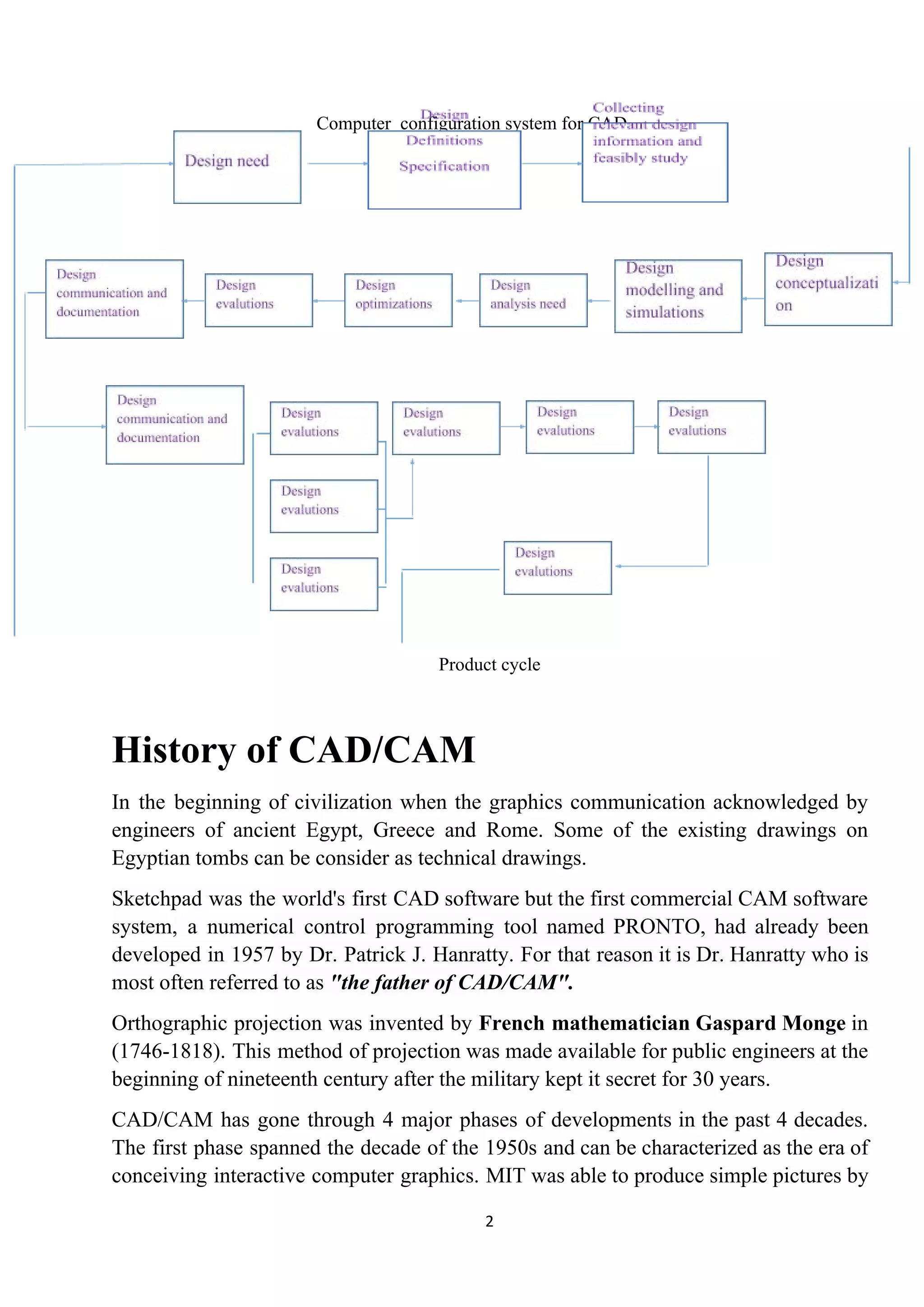
​I​ntroduction to CAD/CAM
Computer – aided design (CAD) can be defined as the use of computer systems to
assist in the creation, modification, analysis, or optimization of a design.
Computer - aided manufacturing (CAM) maybe defined as the support that can be
provided by computer in manufacturing a given product.
CAD/CAM is a term which means computer-aided design and computer-aided
manufacturing. It is the technology concerned with the use of digital computers to
perform certain functions in design and production. This technology is moving in the
direction of greater integration of design and manufacturing, two activities which have
traditionally been treated as distinct and separate functions in a production firm.
Ultimately, CAD/CAM will provide the technology base for the computer-integrated
factory of the future.
CAD/CAM software is used to both design and manufacture products. Autodesk offers
both CAD and CAM software to help make the process cost-effective.
CAD is the use of comp technology for design and design documentation. CAD/CAM
applications are used to both design a product and programme manufacturing
processes, specifically, CNC machining. CAM software uses the models and
assemblies created in CAD software to generate tool paths that drive the machines that
turn the designs into physical parts. CAD/CAM software is most often used for
machining of prototypes and finished parts.
Uses of CAD/CAM software are basically grouped into:
I. Software operator
II. Application programmer
III. System programmer
1
Computer configuration system for CAD
Product cycle
History of CAD/CAM
In the beginning of civilization when the graphics communication acknowledged by
engineers of ancient Egypt, Greece and Rome. Some of the existing drawings on
Egyptian tombs can be consider as technical drawings.
Sketchpad was the world's first CAD software but the first commercial CAM software
system, a numerical control programming tool named PRONTO, had already been
developed in 1957 by Dr. Patrick J. Hanratty. For that reason it is Dr. Hanratty who is
most often referred to as ​"the father of CAD/CAM"​.
Orthographic projection was invented by ​French mathematician Gaspard Monge in
(1746-1818). This method of projection was made available for public engineers at the
beginning of nineteenth century after the military kept it secret for 30 years.
CAD/CAM has gone through 4 major phases of developments in the past 4 decades.
The first phase spanned the decade of the 1950s and can be characterized as the era of
conceiving interactive computer graphics. MIT was able to produce simple pictures by
2
interfacing a television – like CRT (cathode ray tube) with a whirlwind computer in
1950.
The milestone of research achievements was the development of the sketchpad system
by Ivan Sutherland, which was published in 1962 as his thesis. The sketchpad system
was dramatic event because it demonstrated that it was possible to create drawings and
alternations of objects interactively on a CRT.
During the decade of the 1970s the research efforts of the 1960s in computer graphics
had begun to be fruitful and the important potential of interactive computer graphics in
improving was realized by industry, government and academia.
The decade of the 1970s can also be characterized as the golden era for computer
drafting and the beginning of​ ad hoc ​instrumental design applications.
NC tape generations and verifications and integrated circuits were and still are the
well-developed applications available.
​Industrial look at CAD/CAM
For industrial purpose, CAD/CAM package consist of geometric modelling and
graphics, design, manufacturing and programming software.
The utilization and implementation of the Cam technology in an industrial
environmental helps to close the gap between creating the technology the, managing it,
using it and more learning it.
Graphics consists of functions like geometric transformations drafting and
documentations, shading, colouring and layering.
The design consists of mass property calculations, finite element modelling and
analysis, mechanism modelling etc.
If a design application faces problems where standard software cannot be utilized, then
customized software are used. After designing, drafting and documentation are
performed.
Industrial to CIM
CIM (Computer integrated manufacturing) is an extension of CAD/CAM. It integrates
CCAD/CAM system with business functions of an organization.
CIM is a system in which all engineering functions of CAD/CAM are integrated
together.
3
All the functions of CAD and CAM can be utilized along with some of the
manufacturing activities such as material handling.
CIM system applies computer and communication technology to completely integrate
and automates the following four functions:
I. Design
II. Manufacturing planning
III. Manufacturing & control
IV. Business functions
​ NC
​ CAM
​ FMS
ROBOTICS
Computer Simulation
​Optimization
​FEM analysis
​Solid modelling
​CAD
[Integration of technical & business function in CIM]
4
The four basic islands of automation of CIM are as follows:
Island 1 : computer aided design (CAD)
Island 2 : computer aided manufacturing planning (CAMP)
Island 3 : computer aided manufacturing control (CAMC)
Island 4 : computer aided business functions (CABF)
Island 1 : CAD (computer aided design)
The major activities covered under CAD are:
i. Geometric modelling
ii. Engineering analysis
iii. Design review & analysis
iv. Automated drafting
v. Generation of report
Island 2 : CAMP (computer aided manufacturing planning)
CAM is divided into two categories
i. CAMP
ii. CAMC
The CAMP are includes the following
i. Computer aided process planning (CAPP)
ii. Computerized inertial resource planning (CMRP)
iii. Computerized work scheduling (CWS)
iv. NC part programming
Island 3 : CAMC
CAMC are includes the following activities:
i. Computer aided manufacturing by FMS
ii. Computer process monitoring and control
iii. Computer aided quality control
Island 4 : CABF
It includes the following:
i. Purchase inventory & stock control
5
ii. Accounting & billing
iii. Sales order processing
iv. Customer billing
v. Marketing
vi. Plant maintenance
Basic of geometric modelling
Geometric modelling​ is a branch of ​applied mathematics​ and ​computational
geometry​ that studies methods and ​algorithms​ for the mathematical description of
shapes.
The shapes studied in geometric modelling are mostly two- or three-​dimensional​,
although many of its tools and principles can be applied to sets of any finite
dimension. Today most geometric modelling is done with computers and for
computer-based applications.
Two-dimensional models​ are important in computer ​typography​ and ​technical
drawing​. ​Three-dimensional models​ are central to ​computer-aided
design​ and ​manufacturing​ (CAD/CAM), and widely used in many applied technical
fields such as ​civil​ and ​mechanical engineering​, ​architecture​, ​geology​ and ​medical
image processing​.
Geometric models are usually distinguished from ​procedural​ and ​object-oriented
models​, which define the shape implicitly by an opaque ​algorithm​ that generates its
appearance. They are also contrasted with ​digital images​ and ​volumetric models​ which
represent the shape as a subset of a fine regular partition of space; and
with ​fractal​ models that give an infinitely recursive definition of the shape. However,
these distinctions are often blurred: for instance, a ​digital image​ can be interpreted as a
collection of ​colour​ ​squares​; and geometric shapes such as ​circles​ are defined by
implicit mathematical equations. Also, a ​fractal​ model yields a parametric or implicit
model when its recursive definition is truncated to a finite depth.
Salient features of geometric models
Primitive features
Corners: Corners is a very simple but significant feature of objects. Especially,
Complex objects usually have different corner features with each other. Corners of an
object can be extracted by using the technique, calling ​Corner detection​. Cho and
6
Dunn used a different way to define a corner by the distance and angle between two
straight line segments. This is a new way by defining features as a parameterized
composition of several components.
Edges: Edges are one-dimensional structure features of an image. They represent the
boundary of different image regions. The outline of an object can be easily detected by
finding the edge using the technique of ​edge detection​.
Blobs: Blobs represent regions of images, which can be detected using ​blob
detection​ method.
Ridges: From a practical viewpoint, a ridge can be thought of as a one-dimensional
curve that represents an axis of symmetry. Ridges detection method-see ​ridge
detection
Compound features
Geometric composition
Geometric component feature is a combination of several primitive features and it
always consist more than 2 primitive features like edges, corners or blobs. Extracting
geometric feature vector at location x can be computed according to the reference
point, which is shown below:
i i σi dix = x − 1 + − 1 cos os (θi i) in[ c − 1 + Φ sin s (θi i)− 1 + Φ ]
i θi ∆θiθ = − 1 +
Boolean Composition
Boolean compound feature consists of two sub-features which can be primitive
features or compound features. There are two types of Boolean features: conjunctive
feature whose value is the product of two sub-features and disjunctive features whose
value is the maximum of the two sub-features.
Feature space
Feature space was firstly considered in computer vision area by Siegen. He used
multilevel graph to represent the geometric relations of local features.
Learning algorithms
There are many learning algorithms which can be applied to learn to find ​distinctive
features​ of objects in an image. Learning can be incremental, meaning that the object
classes can be added at any time.
Geometric feature extraction methods
7
● Corner detection
● Curve fitting
● Edge detection
● Global structure extraction
● Feature histograms
● Line detection
● Connected-component labelling
● Image texture
● Motion estimation
Methods of geometric modelling
There are three methods of geometric modelling:
I. Wire frame modelling
II. Surface modelling
III. Solid modelling
Wire frame modelling
Wireframe modelling is the process of visual presentation of a three-dimensional or
physical object used in 3-D computer graphics. It is an abstract edge or skeletal
representation of a real-world 3-D object using lines and curves. Because each object
that makes up a wireframe model must be independently drawn and positioned, this
type of modelling can be extremely time-consuming.
The Different Types of wire frame models are as follows:
1. 2D Wire Frame Model
2. D Wire Frame Model22
1
3. 3 D Wire Frame Model
8
2D Wire Frame Model:
Two dimensional representations are used for flat object. It is basically used for
representation objects on any flat plane. All objects which represented on a flat plane
come under 2D Model representation. This plane only gives an idea of the
compounding boundary of any surface boundary on area enclosed on a flat plane. Here
abcd 5 a wire frame model on a flat plane.
2d model
D Wire Frame Model:22
1
This goes further than 2D capacity by permitting 3D Object to be representing as long
as it does not have any sides walls (e.g. cylinder, can be). This kind of on object
simplifies the data’s representation of the object thereby improving the efficiency of
the so frame.
D model22
1
3 D Wire Frame Model:
This type of model represents the skeleton model. It gives the graphic envelope created
by the objects but fails to show the areas, volume i.e. it does not have any finite
volume area.
It just consist of the wire frame streamed, holding no. surface. It does not give a good
idea of the 3D model. Difficulty to analysis as well.
9
3d model
Surface modelling
Surface modelling is a more complex method for representing objects than
wireframe modelling, but not as sophisticated as solid modelling. Surface modelling
widely used in CAD (computer-aided design) for illustrations and architectural
renderings.
Surface model
Basic of solid modelling
Solid modelling (or modelling) is a consistent set of principles for mathematical and
computer modelling of three-dimensional solids. Solid modelling is distinguished from
related areas of geometric modelling and computer graphics by its emphasis on
physical fidelity.
Solid modelling is the most advanced method of geometric modelling in three
dimensions. Solid modelling is the representation of the solid parts of the object on
your computer. The typical geometric model is made up of wire frames that show the
object in the form of wires. This wire frame structure can be two dimensional, two and
half dimensional or three dimensional. Providing surface representation to the wire
three dimensional views of geometric models makes the object appear solid on the
computer screen and this is what is ​called as solid modelling​.
The data required for the constructional of solid models can be divided into two
groups, namely
1. Geometry
2. Topology
Geometry is the actual dimensions that define the entity of the object. The geometry
that defines the object in the fig. given below
10
L1
R
L2 g P1
L3
or
R
L2 P1
L3
i. Length of lines L1, L2, and L3
ii. Angel between lines
iii. Radius ‘R’ of the circle
iv. Centre p1, of the half circle
The solid model of an object is created by using the 3d geometry entities, known as
primitives. Following are the most common types of primitives:
i. Block :-​ it is defined by height, weight & depth.
y
h x
w
z
ii. Cylinder :-​ it is defined by radius & length.
y
x
11
Explicit, implicit & parametric co-ordinate
system
● Curves can be mathematically represents by two methods
● Non – parametric representation & parametric representation
Non – parametric representation
Explicit implicit
● Non – parametric representation
In this, curve is representation as a relation between x, y and z.
● Explicit non – parametric representation
The explicit NPR of 2d curves in the form : y p(x,y)
P = =x y[ ] x f[ (x) ]
x
P = = ox y[ ]
t
x f[ (x) ]
t
The explicit NPR of 3d curves in the form : y p(x,y,z)
P = =x y z[ ] x f g[ (x) (x) ]
x
P = = zx y z[ ]
t
x f g[ (x) (x) ]
t
● Implicit non – parametric representation
The implicit NPR of 2d curves is of the form;
f(x, y) = 0
12
The implicit NPR of 3d curves is of the form;
f(x, y, z) = 0
And g(x, y, z) = 0
Parametric representation
A straight line with slope r through the point (x​0​, y​0​) can be represented parametrically
as y - y​0​ = rt, x - x​0​ = t.
In three dimensions you will also have z - z​0​ = st.
In two dimensions a line can be described as the solution to one linear equation, and in
three dimensions as the solution to two such equations.
A curve similarly can be represented parametrically by expressing the components of a
vector from the origin to a point P with coordinates x, y and z on it, as functions of a
parameter t, or by solutions to one or two equations depending on the dimension of
space.
The difference is that a typical curve is not a line.
Suppose we have a curve represented parametrically.
Here's an example: x = cost, y = sint, z = t.
These particular equations describe the curve known as the "helix".
You can imagine, if it pleases you that the parameter t represents the time variable and
these equations describe the motion of some particle in time.
The equations contain two kinds of information: information about motion along the
curve: that is, the “speed” of the motion along the particle’s orbit, and information
about the orbit or curves itself.
13
14

Introduction to cad

  • 1.
    ​I​ntroduction to CAD/CAM Computer– aided design (CAD) can be defined as the use of computer systems to assist in the creation, modification, analysis, or optimization of a design. Computer - aided manufacturing (CAM) maybe defined as the support that can be provided by computer in manufacturing a given product. CAD/CAM is a term which means computer-aided design and computer-aided manufacturing. It is the technology concerned with the use of digital computers to perform certain functions in design and production. This technology is moving in the direction of greater integration of design and manufacturing, two activities which have traditionally been treated as distinct and separate functions in a production firm. Ultimately, CAD/CAM will provide the technology base for the computer-integrated factory of the future. CAD/CAM software is used to both design and manufacture products. Autodesk offers both CAD and CAM software to help make the process cost-effective. CAD is the use of comp technology for design and design documentation. CAD/CAM applications are used to both design a product and programme manufacturing processes, specifically, CNC machining. CAM software uses the models and assemblies created in CAD software to generate tool paths that drive the machines that turn the designs into physical parts. CAD/CAM software is most often used for machining of prototypes and finished parts. Uses of CAD/CAM software are basically grouped into: I. Software operator II. Application programmer III. System programmer 1
  • 2.
    Computer configuration systemfor CAD Product cycle History of CAD/CAM In the beginning of civilization when the graphics communication acknowledged by engineers of ancient Egypt, Greece and Rome. Some of the existing drawings on Egyptian tombs can be consider as technical drawings. Sketchpad was the world's first CAD software but the first commercial CAM software system, a numerical control programming tool named PRONTO, had already been developed in 1957 by Dr. Patrick J. Hanratty. For that reason it is Dr. Hanratty who is most often referred to as ​"the father of CAD/CAM"​. Orthographic projection was invented by ​French mathematician Gaspard Monge in (1746-1818). This method of projection was made available for public engineers at the beginning of nineteenth century after the military kept it secret for 30 years. CAD/CAM has gone through 4 major phases of developments in the past 4 decades. The first phase spanned the decade of the 1950s and can be characterized as the era of conceiving interactive computer graphics. MIT was able to produce simple pictures by 2
  • 3.
    interfacing a television– like CRT (cathode ray tube) with a whirlwind computer in 1950. The milestone of research achievements was the development of the sketchpad system by Ivan Sutherland, which was published in 1962 as his thesis. The sketchpad system was dramatic event because it demonstrated that it was possible to create drawings and alternations of objects interactively on a CRT. During the decade of the 1970s the research efforts of the 1960s in computer graphics had begun to be fruitful and the important potential of interactive computer graphics in improving was realized by industry, government and academia. The decade of the 1970s can also be characterized as the golden era for computer drafting and the beginning of​ ad hoc ​instrumental design applications. NC tape generations and verifications and integrated circuits were and still are the well-developed applications available. ​Industrial look at CAD/CAM For industrial purpose, CAD/CAM package consist of geometric modelling and graphics, design, manufacturing and programming software. The utilization and implementation of the Cam technology in an industrial environmental helps to close the gap between creating the technology the, managing it, using it and more learning it. Graphics consists of functions like geometric transformations drafting and documentations, shading, colouring and layering. The design consists of mass property calculations, finite element modelling and analysis, mechanism modelling etc. If a design application faces problems where standard software cannot be utilized, then customized software are used. After designing, drafting and documentation are performed. Industrial to CIM CIM (Computer integrated manufacturing) is an extension of CAD/CAM. It integrates CCAD/CAM system with business functions of an organization. CIM is a system in which all engineering functions of CAD/CAM are integrated together. 3
  • 4.
    All the functionsof CAD and CAM can be utilized along with some of the manufacturing activities such as material handling. CIM system applies computer and communication technology to completely integrate and automates the following four functions: I. Design II. Manufacturing planning III. Manufacturing & control IV. Business functions ​ NC ​ CAM ​ FMS ROBOTICS Computer Simulation ​Optimization ​FEM analysis ​Solid modelling ​CAD [Integration of technical & business function in CIM] 4
  • 5.
    The four basicislands of automation of CIM are as follows: Island 1 : computer aided design (CAD) Island 2 : computer aided manufacturing planning (CAMP) Island 3 : computer aided manufacturing control (CAMC) Island 4 : computer aided business functions (CABF) Island 1 : CAD (computer aided design) The major activities covered under CAD are: i. Geometric modelling ii. Engineering analysis iii. Design review & analysis iv. Automated drafting v. Generation of report Island 2 : CAMP (computer aided manufacturing planning) CAM is divided into two categories i. CAMP ii. CAMC The CAMP are includes the following i. Computer aided process planning (CAPP) ii. Computerized inertial resource planning (CMRP) iii. Computerized work scheduling (CWS) iv. NC part programming Island 3 : CAMC CAMC are includes the following activities: i. Computer aided manufacturing by FMS ii. Computer process monitoring and control iii. Computer aided quality control Island 4 : CABF It includes the following: i. Purchase inventory & stock control 5
  • 6.
    ii. Accounting &billing iii. Sales order processing iv. Customer billing v. Marketing vi. Plant maintenance Basic of geometric modelling Geometric modelling​ is a branch of ​applied mathematics​ and ​computational geometry​ that studies methods and ​algorithms​ for the mathematical description of shapes. The shapes studied in geometric modelling are mostly two- or three-​dimensional​, although many of its tools and principles can be applied to sets of any finite dimension. Today most geometric modelling is done with computers and for computer-based applications. Two-dimensional models​ are important in computer ​typography​ and ​technical drawing​. ​Three-dimensional models​ are central to ​computer-aided design​ and ​manufacturing​ (CAD/CAM), and widely used in many applied technical fields such as ​civil​ and ​mechanical engineering​, ​architecture​, ​geology​ and ​medical image processing​. Geometric models are usually distinguished from ​procedural​ and ​object-oriented models​, which define the shape implicitly by an opaque ​algorithm​ that generates its appearance. They are also contrasted with ​digital images​ and ​volumetric models​ which represent the shape as a subset of a fine regular partition of space; and with ​fractal​ models that give an infinitely recursive definition of the shape. However, these distinctions are often blurred: for instance, a ​digital image​ can be interpreted as a collection of ​colour​ ​squares​; and geometric shapes such as ​circles​ are defined by implicit mathematical equations. Also, a ​fractal​ model yields a parametric or implicit model when its recursive definition is truncated to a finite depth. Salient features of geometric models Primitive features Corners: Corners is a very simple but significant feature of objects. Especially, Complex objects usually have different corner features with each other. Corners of an object can be extracted by using the technique, calling ​Corner detection​. Cho and 6
  • 7.
    Dunn used adifferent way to define a corner by the distance and angle between two straight line segments. This is a new way by defining features as a parameterized composition of several components. Edges: Edges are one-dimensional structure features of an image. They represent the boundary of different image regions. The outline of an object can be easily detected by finding the edge using the technique of ​edge detection​. Blobs: Blobs represent regions of images, which can be detected using ​blob detection​ method. Ridges: From a practical viewpoint, a ridge can be thought of as a one-dimensional curve that represents an axis of symmetry. Ridges detection method-see ​ridge detection Compound features Geometric composition Geometric component feature is a combination of several primitive features and it always consist more than 2 primitive features like edges, corners or blobs. Extracting geometric feature vector at location x can be computed according to the reference point, which is shown below: i i σi dix = x − 1 + − 1 cos os (θi i) in[ c − 1 + Φ sin s (θi i)− 1 + Φ ] i θi ∆θiθ = − 1 + Boolean Composition Boolean compound feature consists of two sub-features which can be primitive features or compound features. There are two types of Boolean features: conjunctive feature whose value is the product of two sub-features and disjunctive features whose value is the maximum of the two sub-features. Feature space Feature space was firstly considered in computer vision area by Siegen. He used multilevel graph to represent the geometric relations of local features. Learning algorithms There are many learning algorithms which can be applied to learn to find ​distinctive features​ of objects in an image. Learning can be incremental, meaning that the object classes can be added at any time. Geometric feature extraction methods 7
  • 8.
    ● Corner detection ●Curve fitting ● Edge detection ● Global structure extraction ● Feature histograms ● Line detection ● Connected-component labelling ● Image texture ● Motion estimation Methods of geometric modelling There are three methods of geometric modelling: I. Wire frame modelling II. Surface modelling III. Solid modelling Wire frame modelling Wireframe modelling is the process of visual presentation of a three-dimensional or physical object used in 3-D computer graphics. It is an abstract edge or skeletal representation of a real-world 3-D object using lines and curves. Because each object that makes up a wireframe model must be independently drawn and positioned, this type of modelling can be extremely time-consuming. The Different Types of wire frame models are as follows: 1. 2D Wire Frame Model 2. D Wire Frame Model22 1 3. 3 D Wire Frame Model 8
  • 9.
    2D Wire FrameModel: Two dimensional representations are used for flat object. It is basically used for representation objects on any flat plane. All objects which represented on a flat plane come under 2D Model representation. This plane only gives an idea of the compounding boundary of any surface boundary on area enclosed on a flat plane. Here abcd 5 a wire frame model on a flat plane. 2d model D Wire Frame Model:22 1 This goes further than 2D capacity by permitting 3D Object to be representing as long as it does not have any sides walls (e.g. cylinder, can be). This kind of on object simplifies the data’s representation of the object thereby improving the efficiency of the so frame. D model22 1 3 D Wire Frame Model: This type of model represents the skeleton model. It gives the graphic envelope created by the objects but fails to show the areas, volume i.e. it does not have any finite volume area. It just consist of the wire frame streamed, holding no. surface. It does not give a good idea of the 3D model. Difficulty to analysis as well. 9
  • 10.
    3d model Surface modelling Surfacemodelling is a more complex method for representing objects than wireframe modelling, but not as sophisticated as solid modelling. Surface modelling widely used in CAD (computer-aided design) for illustrations and architectural renderings. Surface model Basic of solid modelling Solid modelling (or modelling) is a consistent set of principles for mathematical and computer modelling of three-dimensional solids. Solid modelling is distinguished from related areas of geometric modelling and computer graphics by its emphasis on physical fidelity. Solid modelling is the most advanced method of geometric modelling in three dimensions. Solid modelling is the representation of the solid parts of the object on your computer. The typical geometric model is made up of wire frames that show the object in the form of wires. This wire frame structure can be two dimensional, two and half dimensional or three dimensional. Providing surface representation to the wire three dimensional views of geometric models makes the object appear solid on the computer screen and this is what is ​called as solid modelling​. The data required for the constructional of solid models can be divided into two groups, namely 1. Geometry 2. Topology Geometry is the actual dimensions that define the entity of the object. The geometry that defines the object in the fig. given below 10
  • 11.
    L1 R L2 g P1 L3 or R L2P1 L3 i. Length of lines L1, L2, and L3 ii. Angel between lines iii. Radius ‘R’ of the circle iv. Centre p1, of the half circle The solid model of an object is created by using the 3d geometry entities, known as primitives. Following are the most common types of primitives: i. Block :-​ it is defined by height, weight & depth. y h x w z ii. Cylinder :-​ it is defined by radius & length. y x 11
  • 12.
    Explicit, implicit &parametric co-ordinate system ● Curves can be mathematically represents by two methods ● Non – parametric representation & parametric representation Non – parametric representation Explicit implicit ● Non – parametric representation In this, curve is representation as a relation between x, y and z. ● Explicit non – parametric representation The explicit NPR of 2d curves in the form : y p(x,y) P = =x y[ ] x f[ (x) ] x P = = ox y[ ] t x f[ (x) ] t The explicit NPR of 3d curves in the form : y p(x,y,z) P = =x y z[ ] x f g[ (x) (x) ] x P = = zx y z[ ] t x f g[ (x) (x) ] t ● Implicit non – parametric representation The implicit NPR of 2d curves is of the form; f(x, y) = 0 12
  • 13.
    The implicit NPRof 3d curves is of the form; f(x, y, z) = 0 And g(x, y, z) = 0 Parametric representation A straight line with slope r through the point (x​0​, y​0​) can be represented parametrically as y - y​0​ = rt, x - x​0​ = t. In three dimensions you will also have z - z​0​ = st. In two dimensions a line can be described as the solution to one linear equation, and in three dimensions as the solution to two such equations. A curve similarly can be represented parametrically by expressing the components of a vector from the origin to a point P with coordinates x, y and z on it, as functions of a parameter t, or by solutions to one or two equations depending on the dimension of space. The difference is that a typical curve is not a line. Suppose we have a curve represented parametrically. Here's an example: x = cost, y = sint, z = t. These particular equations describe the curve known as the "helix". You can imagine, if it pleases you that the parameter t represents the time variable and these equations describe the motion of some particle in time. The equations contain two kinds of information: information about motion along the curve: that is, the “speed” of the motion along the particle’s orbit, and information about the orbit or curves itself. 13
  • 14.