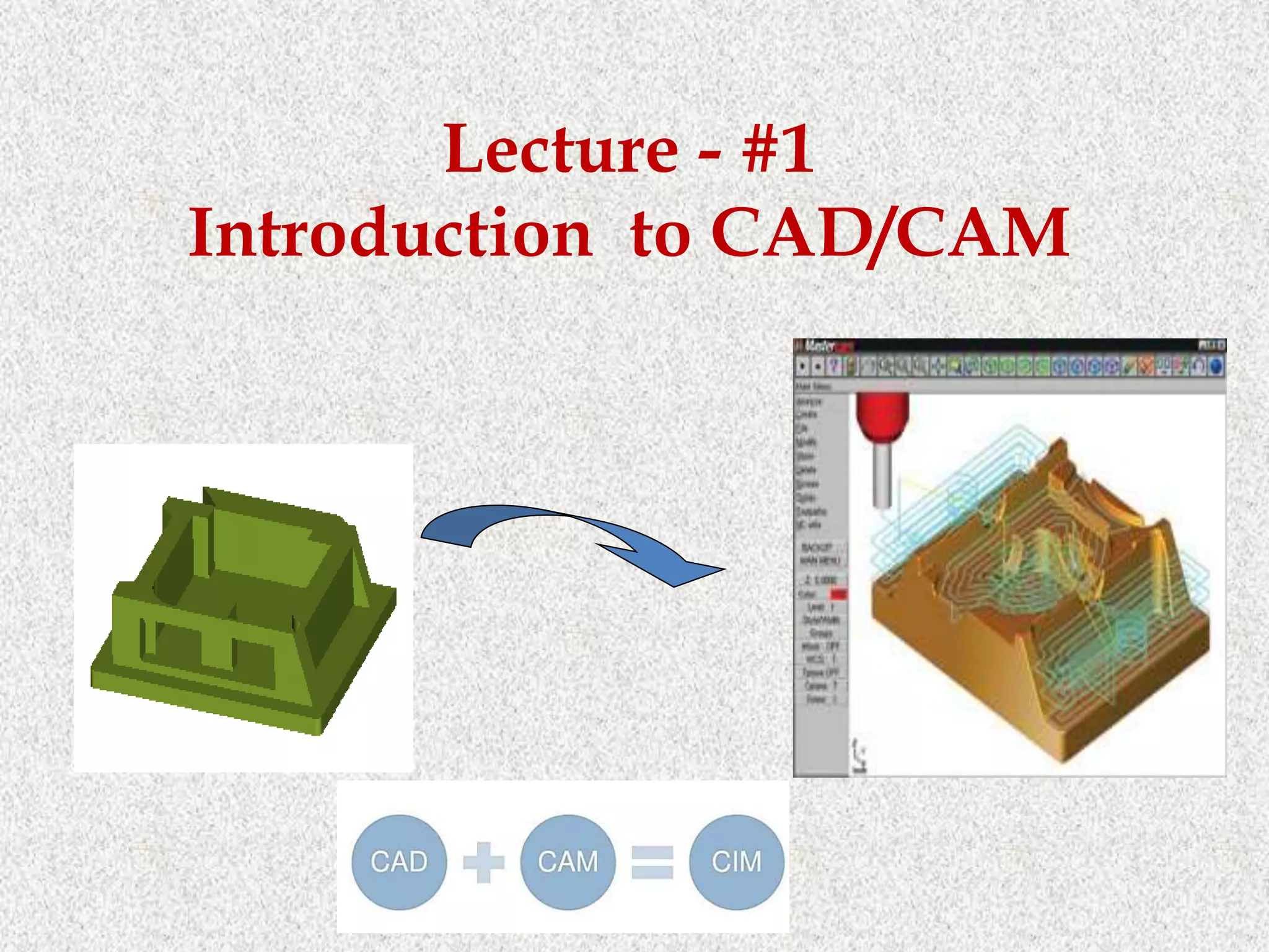
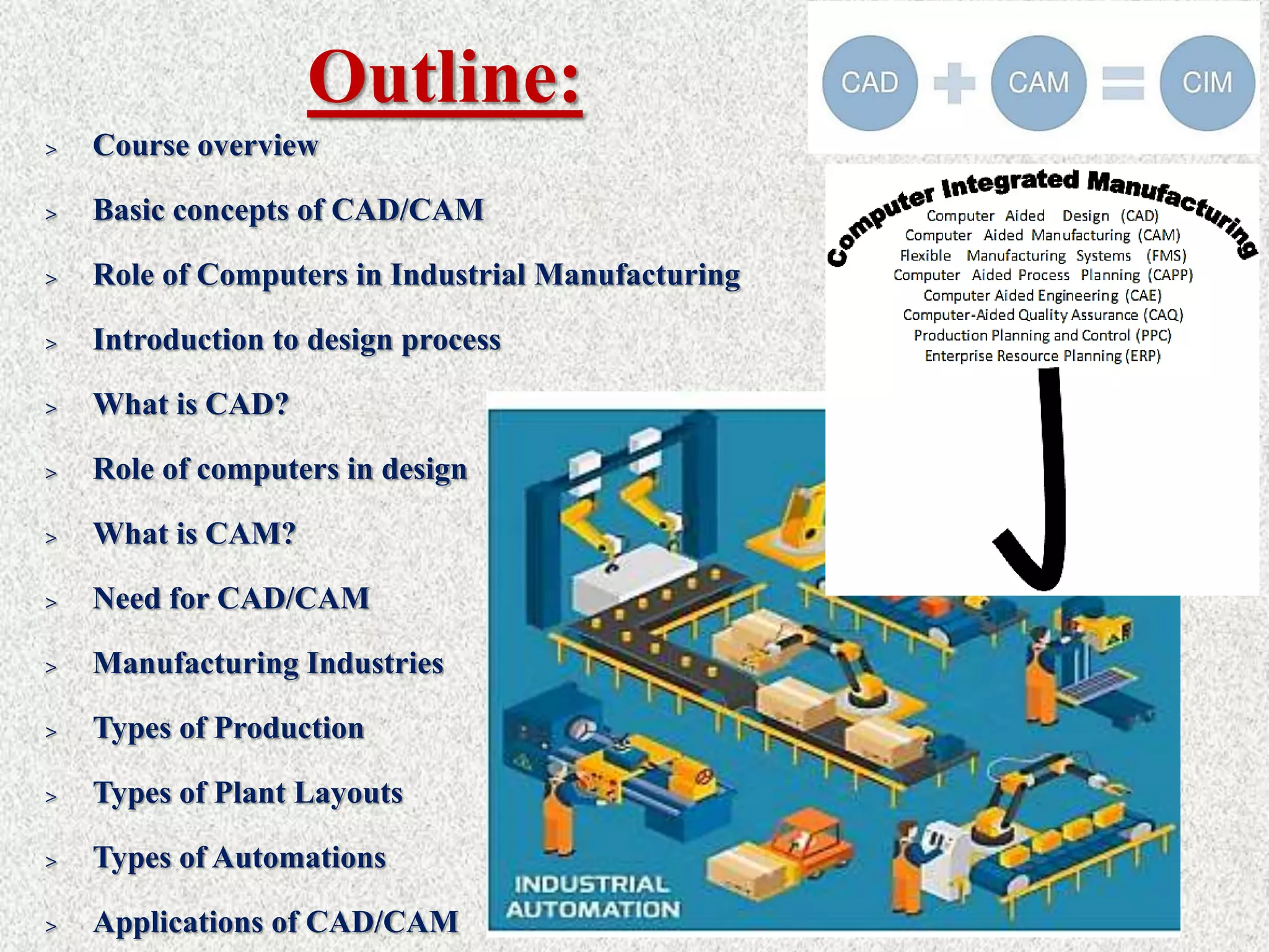
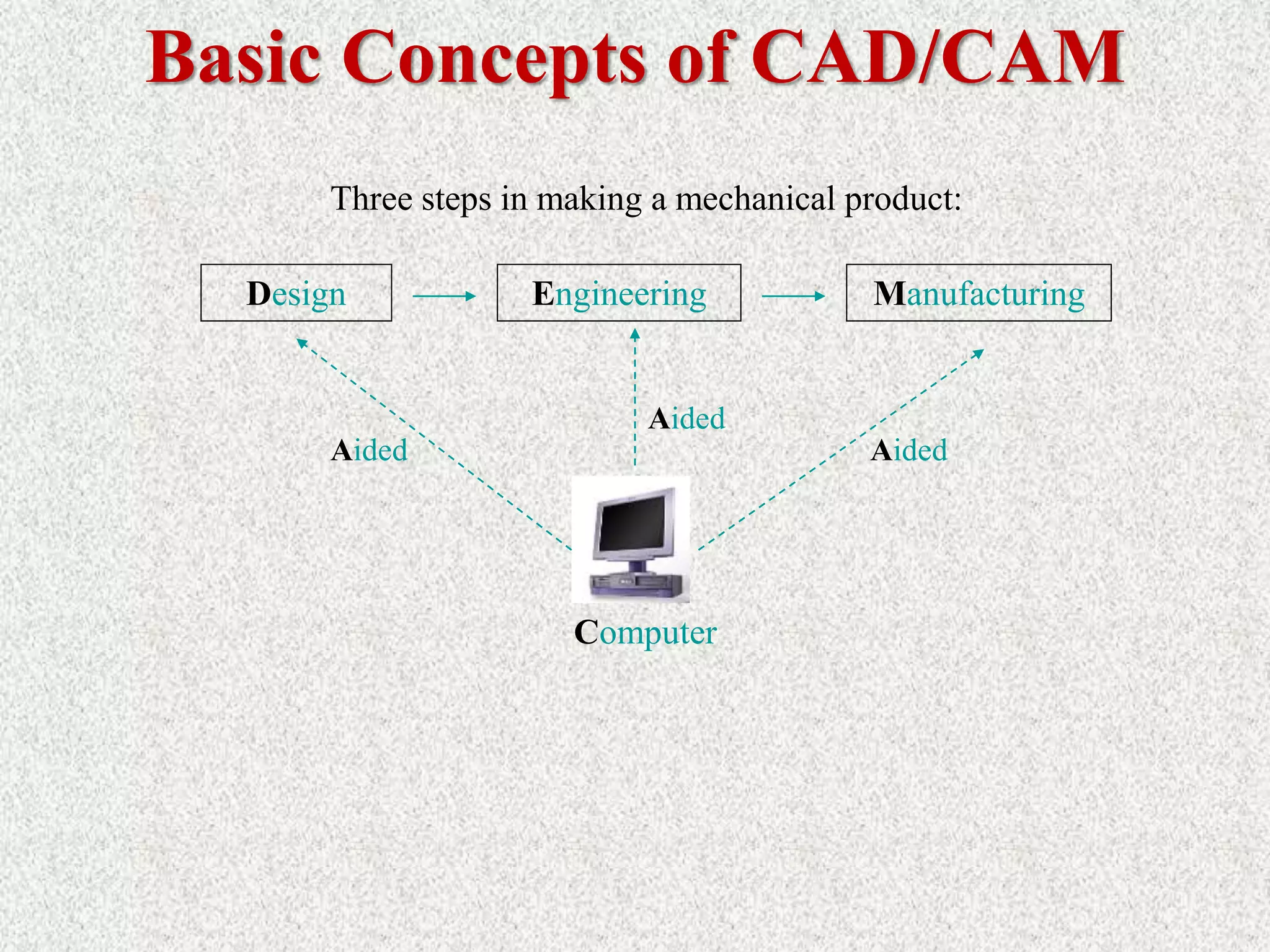
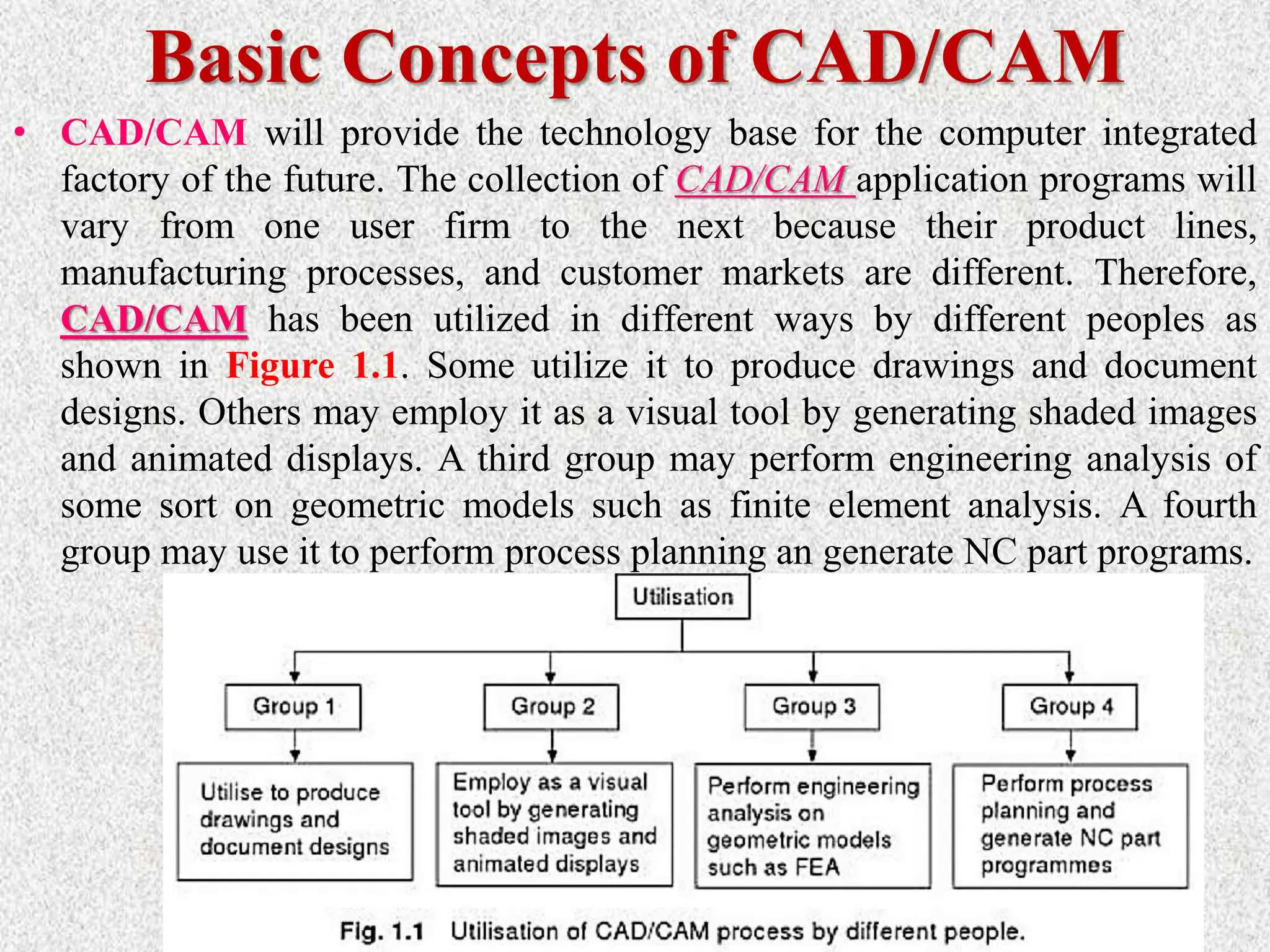
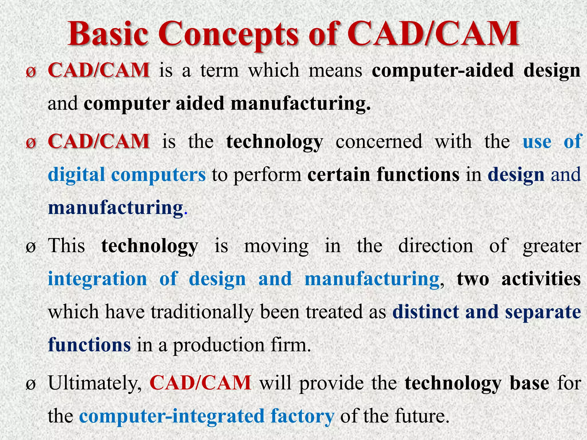
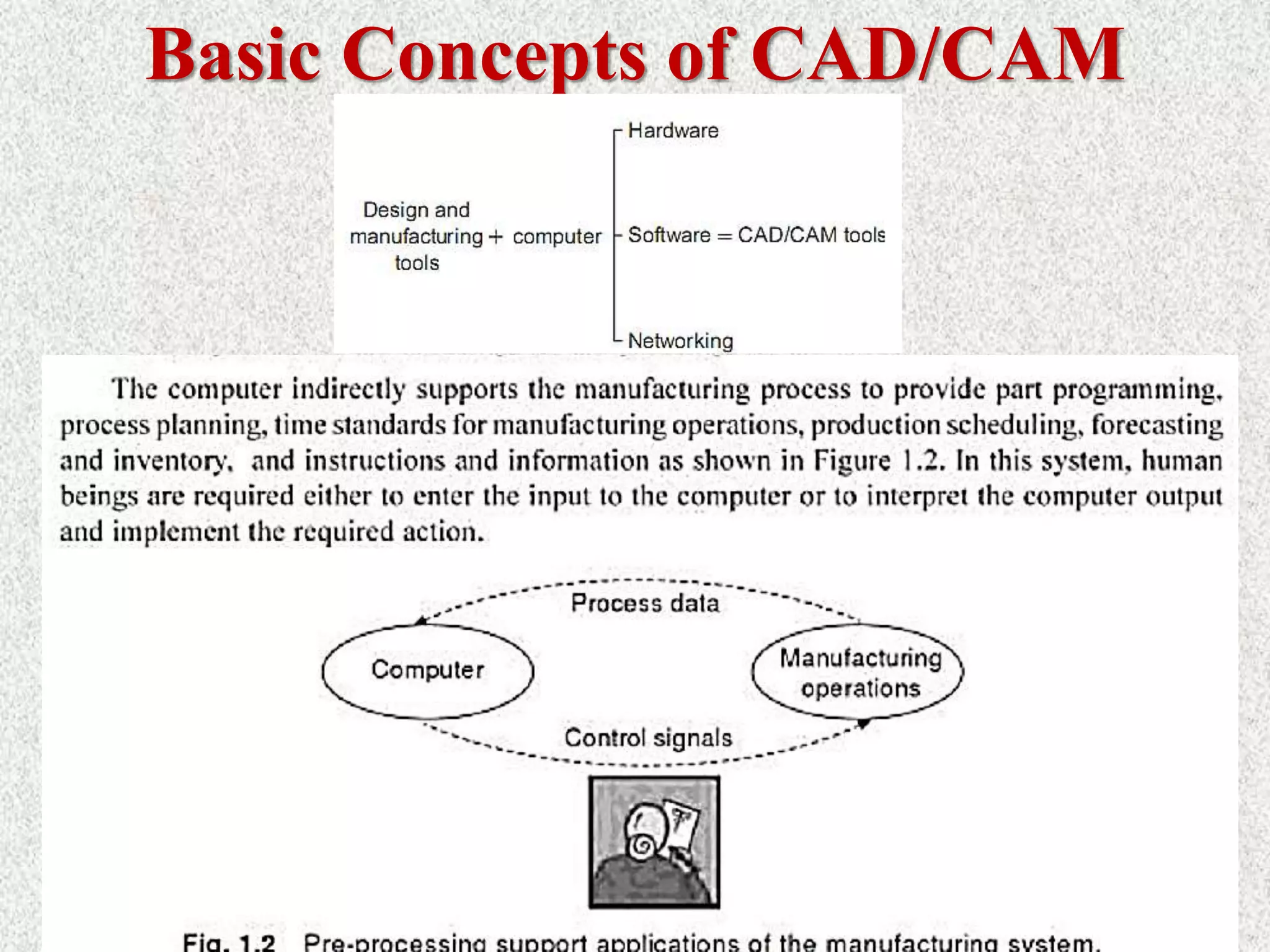
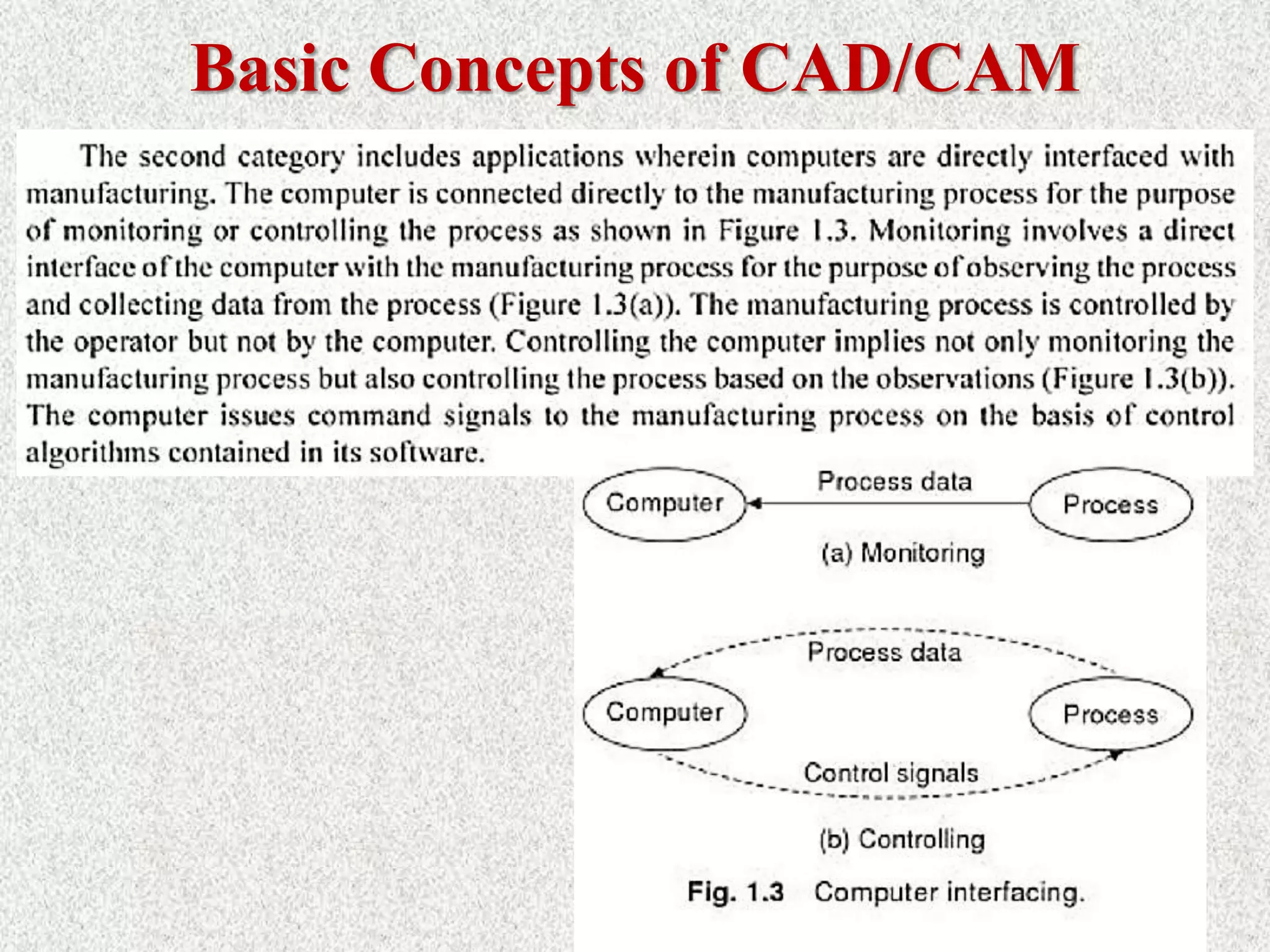
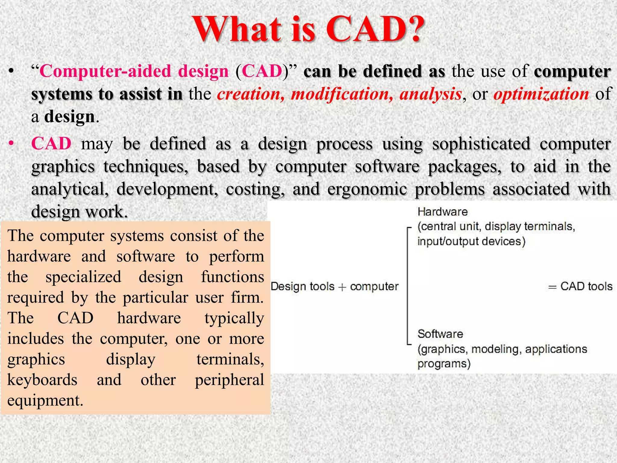
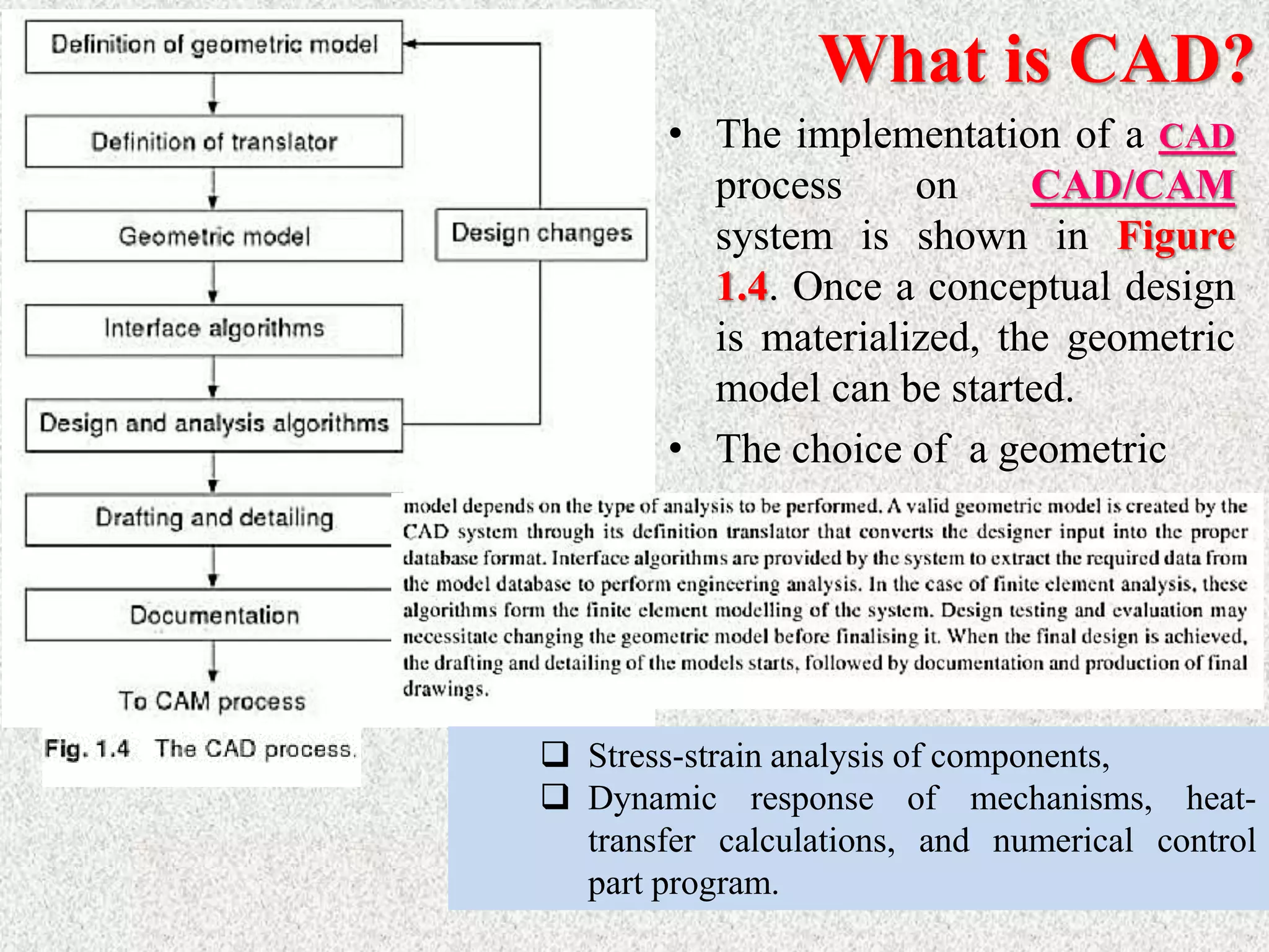
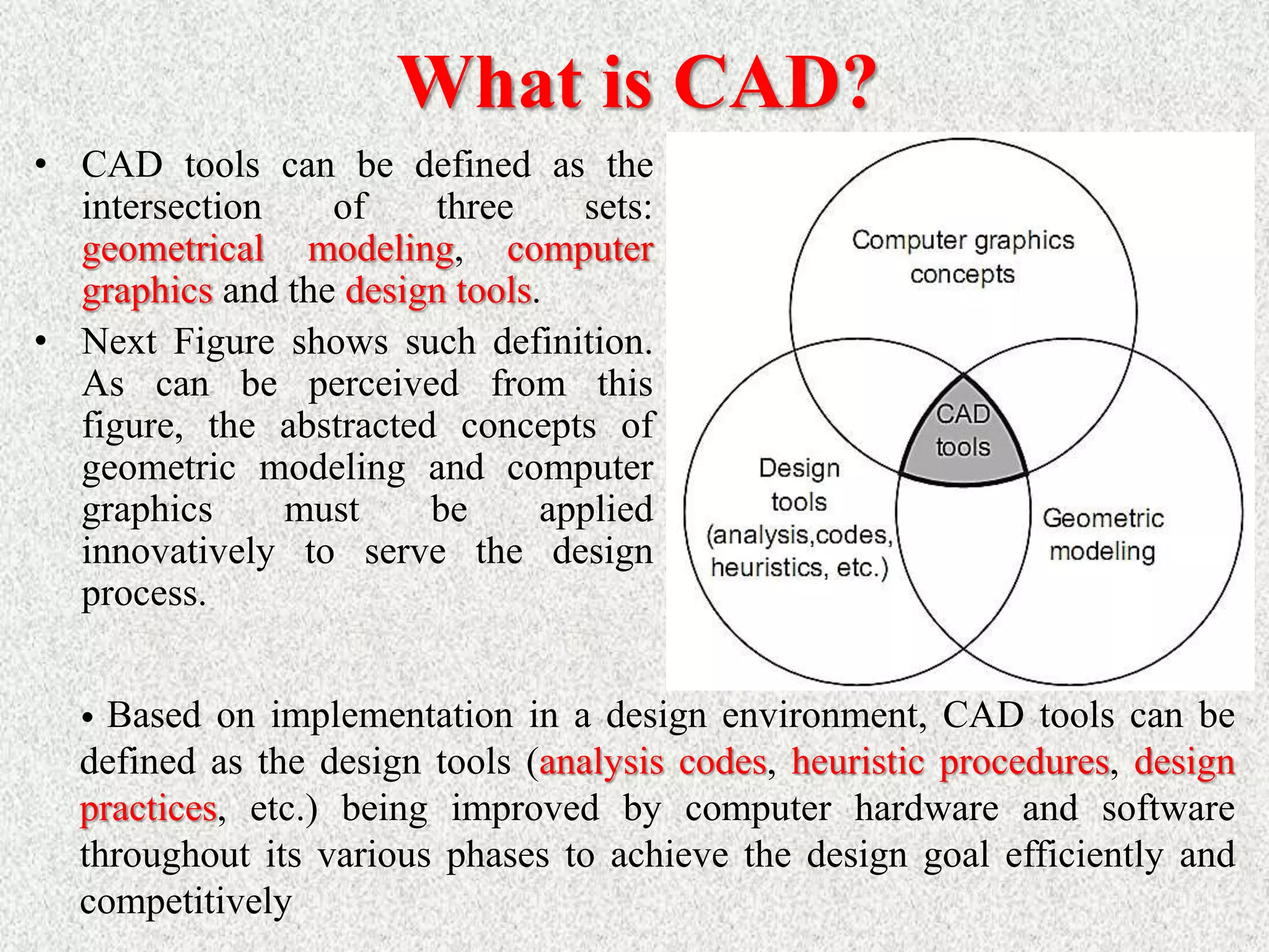
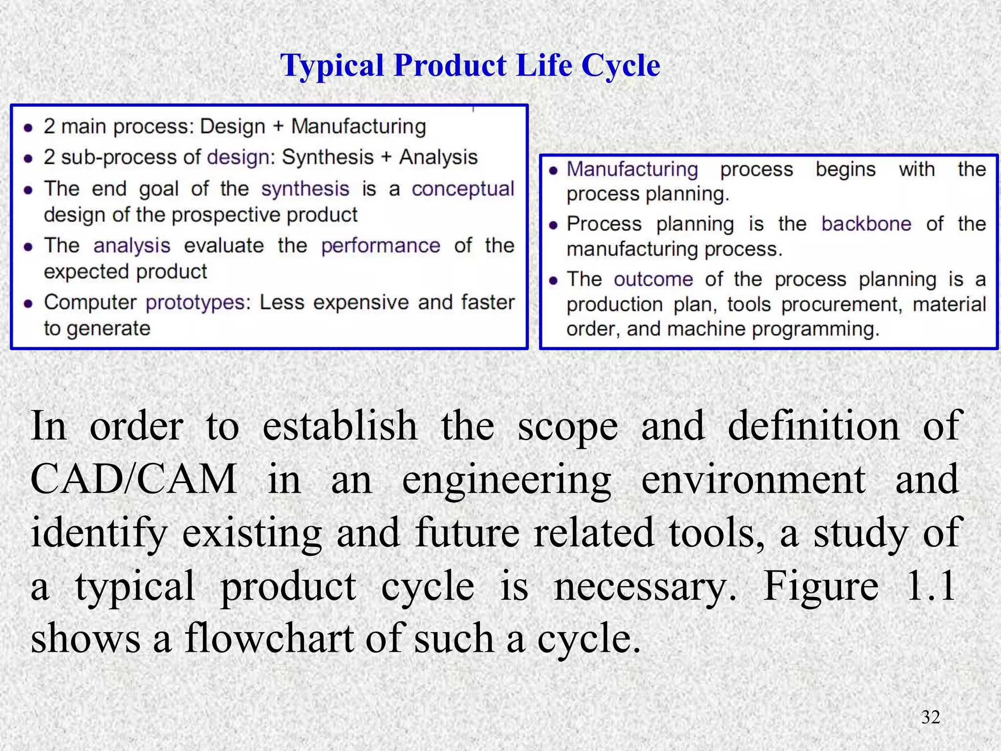
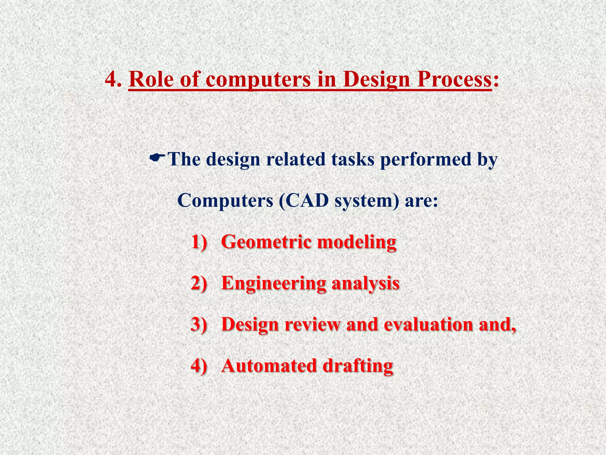
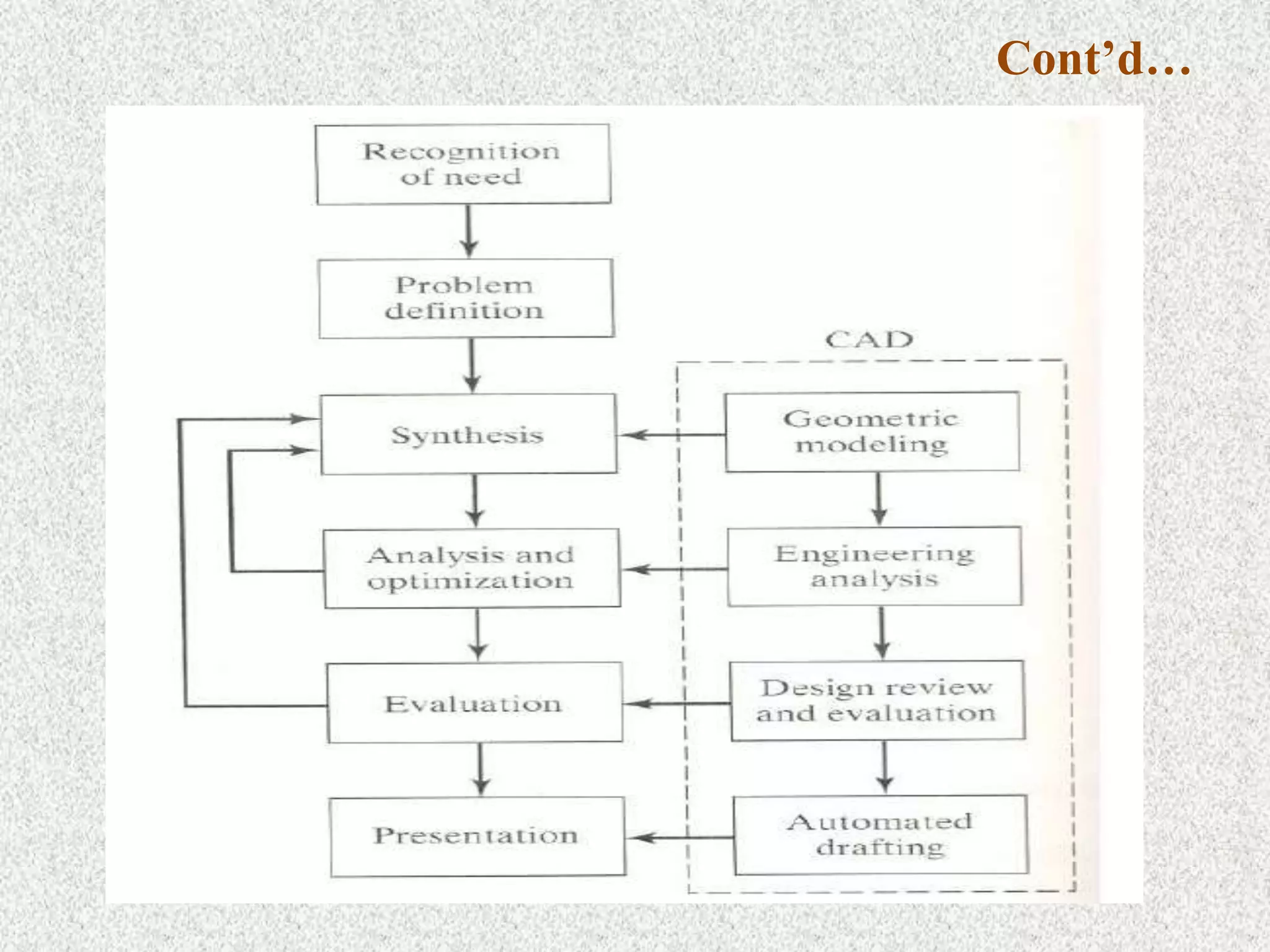
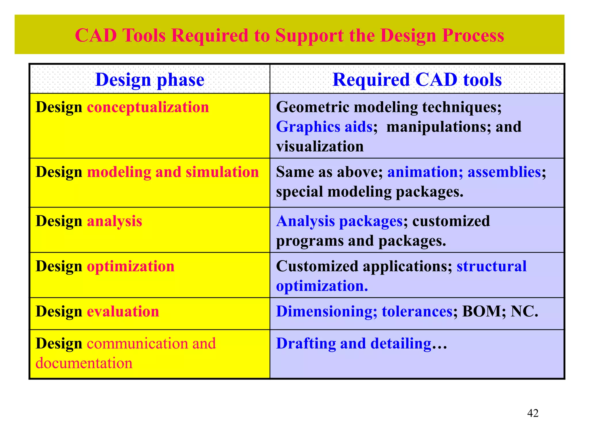
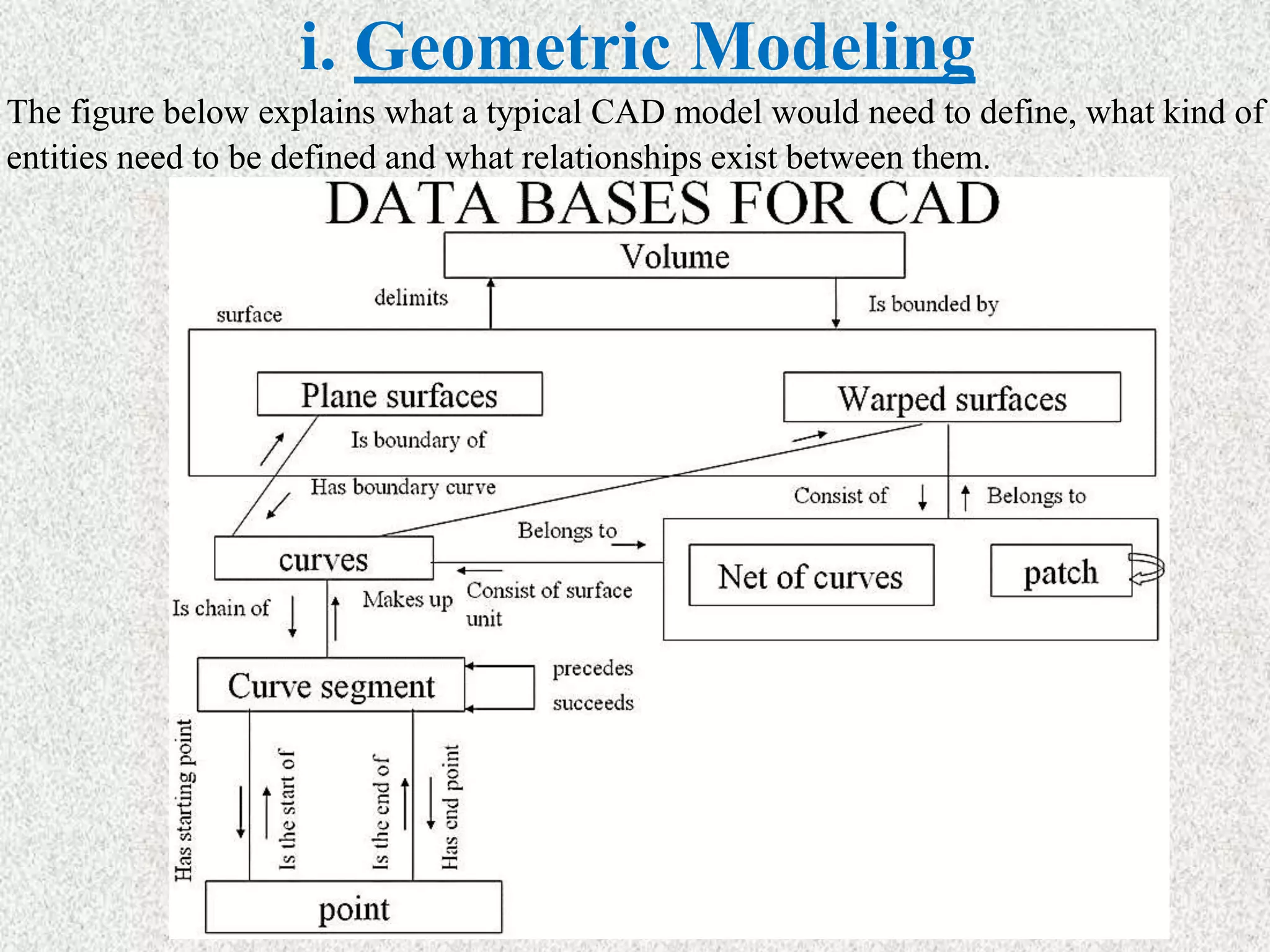
Lecture - #1
Introduction to CAD/CAM
Outline:
> Course overview
> Basic concepts of CAD/CAM
> Role of Computers in Industrial Manufacturing
> Introduction to design process
> What is CAD?
> Role of computers in design
> What is CAM?
> Need for CAD/CAM
> Manufacturing Industries
> Types of Production
> Types of Plant Layouts
> Types of Automations
> Applications of CAD/CAM
Course overview
Course overview
Basic Concepts of CAD/CAM
• In a computer ıntegrated manufacturing (CIM) system functional areas such as
design, analysis, planning, purchasing, cost accounting, inventory control, and
distribution are linked through the computer with factory floor functions such as
materials handling and management, providing direct control and monitoring of all
the operations.
Basic Concepts of CAD/CAM
Design Engineering Manufacturing
Three steps in making a mechanical product:
Computer
Aided
Aided
Aided
• Many CAD vendors market fully integrated CAM systems, aptly called CAD/CAM
systems. These CAD/CAM packages deliver many advantages. For starters, they feature
a common user interface that allows CAD operators to quickly learn the software.
Moreover, users can easily transfer CAD data to the CAM system without worrying
about translation errors or other difficulties. And finally, some integrated systems
provide full associatively, which means that any modification to the CAD model will
prompt the associated tool path to be automatically updated.
• Computer Aided Design (CAD) has completely changed the drafting business and made
the storage and retrieval of projects much easier. However, manual drawing is still very
important and provides the basics of learning to draw.
• The first CAD systems were mainframe computer supported systems, while today the
technology is for networked but stand alone operating workstations (UNIX or
WINDOWS based systems). AUTODESK was the first vendor to offer a PC based CAD
system the AUTOCAD (beginning of 1980). Today WINDOWS is the main operating
system for CAD systems.
• The first applications were for 2D-Drafting and the systems were also capable of
performing only 2D modeling. Even today 2D-drafting is still the main area of
application (in terms of number of workplaces). Later, (mid-1980), following the
progress in 3D modeling technology and the growth in the IT H/W, 3D modeling
systems are becoming very popular. 3D modeling are at the beginning wire frame based.
Basic Concepts of CAD/CAM
• CAD/CAM will provide the technology base for the computer integrated
factory of the future. The collection of CAD/CAM application programs will
vary from one user firm to the next because their product lines,
manufacturing processes, and customer markets are different. Therefore,
CAD/CAM has been utilized in different ways by different peoples as
shown in Figure 1.1. Some utilize it to produce drawings and document
designs. Others may employ it as a visual tool by generating shaded images
and animated displays. A third group may perform engineering analysis of
some sort on geometric models such as finite element analysis. A fourth
group may use it to perform process planning an generate NC part programs.
Basic Concepts of CAD/CAM
ø CAD/CAM is a term which means computer-aided design
and computer aided manufacturing.
ø CAD/CAM is the technology concerned with the use of
digital computers to perform certain functions in design and
manufacturing.
ø This technology is moving in the direction of greater
integration of design and manufacturing, two activities
which have traditionally been treated as distinct and separate
functions in a production firm.
ø Ultimately, CAD/CAM will provide the technology base for
the computer-integrated factory of the future.
Role of Computers in Industrial Manufacturing
• The role of computers in industrial manufacturing fall into three
broad categories:
Basic Concepts of CAD/CAM
Introduction to Design Process
Product design is a critical function in the production
system.
The quality of the product design (i.e., how well the design
department single most does its job) is probably the important
factor in determining the commercial.
If the success and societal value of a product is poor, no
matter how well it is manufactured, it is not acceptable by
the users.
If the product design is good, there is still the question of
whether the product can be produced at sufficiently low cost
to contribute to the company's profits and success.
Cont’d…
> Engineering product design begins with a need
which is identified based on customers’ and markets‘
demand.
> The product goes through two main processes from
the idea conceptualization to the finished product:
1) The design process and,
2) The manufacturing process
Design Process:
> The process of designing something is
characterized as an interactive procedure,
which consists of six identifiable steps or
phases:
1) Recognition of need
2) Definition of the need
3) Synthesis
4) Analysis and optimization
5) Evaluation
6) Presentation
Cont’d…
 Recognition of needs involves realization by someone that a problem exists
for which some corrective action can be taken in the form of a design solution.
 Problem definition of design by an engineer involves a thorough specification
of the item to be designed. This specification includes the physical
characteristics, function, cost, quality, and operating performance.
 Synthesis and analysis highly interactive in the design process. Consider the
development of a certain product design: Each of the subsystems of the
product must be conceptualized by the designer, analyzed, improved through
this analysis procedure, redesigned, analyzed again, and so on. The process is
repeated until the design has been optimized within the constraints imposed
on the designer. The individual components are then synthesized and analyzed
into the final product in a similar manner.
Cont’d…
# Evaluation: is concerned with measuring the design against
the specifications established in the problem definition phase.
This evaluation often requires the fabrication and testing of a
prototype model to assess operating performance, quality,
reliability, and other criteria.
# Presentation: The final phase in the design procedure. The
presentation is concerned with documenting the design by
means of drawings, material specifications, assembly lists,
and so on. In essence, documentation means that the design data
base is created.
Traditional Design Process:
Design  Make prototype Test Redesign
Loop
Problems in traditional design
Process:
Suboptimal design solution
 Costly
 Slow to response the market.
What is CAD?
• “Computer-aided design (CAD)” can be defined as the use of computer
systems to assist in the creation, modification, analysis, or optimization of
a design.
• CAD may be defined as a design process using sophisticated computer
graphics techniques, based by computer software packages, to aid in the
analytical, development, costing, and ergonomic problems associated with
design work.
The computer systems consist of the
hardware and software to perform
the specialized design functions
required by the particular user firm.
The CAD hardware typically
includes the computer, one or more
graphics display terminals,
keyboards and other peripheral
equipment.
ø CAD Technology = Design Techniques + Computers (HW+SW).
ø CAD involves the effective use of the computer to create, modify, analyze, or document
an engineering design.
ø CAD is most commonly associated with the use of an interactive computer graphics
system, referred to as a CAD system.
ø The computer systems consist of the hardware and software to perform the
specialized design functions required by the particular user firm.
ø The CAD hardware typically includes the computer, one or more graphics
display terminals, keyboards, and other peripheral equipment.
ø The CAD software consists of the computer programs to implement computer
graphics on the system plus application programs to facilitate the engineering
functions of the user company
What is CAD?
What is CAD?
• The implementation of a CAD
process on CAD/CAM
system is shown in Figure
1.4. Once a conceptual design
is materialized, the geometric
model can be started.
• The choice of a geometric
 Stress-strain analysis of components,
 Dynamic response of mechanisms, heat-
transfer calculations, and numerical control
part program.
What is CAD?
• CAD tools can be defined as the
intersection of three sets:
geometrical modeling, computer
graphics and the design tools.
• Next Figure shows such definition.
As can be perceived from this
figure, the abstracted concepts of
geometric modeling and computer
graphics must be applied
innovatively to serve the design
process.
• Based on implementation in a design environment, CAD tools can be
defined as the design tools (analysis codes, heuristic procedures, design
practices, etc.) being improved by computer hardware and software
throughout its various phases to achieve the design goal efficiently and
competitively
What is CAD?
CAD if often defined in a variety of ways and includes a large
range of activities. Very broadly it can be said to be the
integration of computer science (or software) techniques in
engineering design. At one end when we talk of modeling, It
encompasses the following:
 Use of computers (hardware & software) for designing
products
 Numerical method, optimizations etc.
 2D/3D drafting
 3D modeling for visualization
 Modeling curves, surfaces, solids, mechanism,
assemblies, etc.
What is CAD?
The models thus developed are first visualized on display monitors
using a variety of techniques including wire frame display, shaded
image display, hidden surface removed display and so on. Once the
designer is satisfied, these models are then used for various types of
analysis / applications. thus, at the other end it includes a number of
analysis activities. These could be:
 Stress (or deflection) analysis, i.e. numerical methods meant for
estimating the behavior of an artifact with respect to these
parameters. It includes tools like the Finite Element Method (FEM).
 Simulation of actual use
 Optimization
 Other applications like
o CAD/CAM integration
o Process planning
 These are activities which normally use models developed using
one or more of the techniques mentioned above. These activities are
often included in other umbrellas like CAM or CAE. A term often
used is CAx to include this broad set of activities. They all use
CAD models and often the kind of application they have to be used
in determines the kind of a model to be developed. Hence, in this
course we cover them under the umbrella of CAD. In this course
we will strive to give an overview of modelling techniques
followed by some applications, specifically CAM.
 Thus there are three aspects to CAD.
 Modeling
 Display/ Visualization
 Applications
What is CAD?
32
Typical Product Life Cycle
In order to establish the scope and definition of
CAD/CAM in an engineering environment and
identify existing and future related tools, a study of
a typical product cycle is necessary. Figure 1.1
shows a flowchart of such a cycle.
Product Cycle in Conventional Manufacturing
Environment
Product Cycle in an Computerized Manufacturing
Environment
35
The Manufacturing Process
The Design Process
Synthesis
Analysis The CAD Process
The CAM Process
Design
needs
Design
definitions,
specifications,
and requirements
Collecting
relevant design
information and
feasibility study
Design
conceptualization
Design
modeling and
simulation
Design
analysis
Design
optimization
Design
evaluation
Design
documentation and
communication
Process
planning
Order
materials
Design and
procurement of
new tools
Production
planning
NC, CNC, DNC
programming
Production
Quality
control
Packaging
Marketing
Shipping
Typical Product Life Cycle
36
3. Benefits of use of computers in design process
Fundamental reasons for implementing computers in design
(CAD/CAD system):
1. To increase the productivity of the designer.
> This is accomplished by helping the designer to conceptualize the
product and its components. In turn, this helps to reduce the time
required by the designer to synthesize, analyze, and document the
design.
2. To improve the quality of design.
> The use of a CAD system with appropriate hardware and software
capabilities permits the designer to do a more complete engineering
analysis and to consider a larger number and variety of design
Cont’d…
3. To improve documentation
> The graphical output of a CAD system results in better
documentation of the design than what is practical with manual
drafting. The engineering drawings are superior, and there is more
standardization among the drawings, fewer drafting errors, and
greater legibility.
4. To create a data base for manufacturing.
> In the process of creating the documentation for the product design
(geometric specification of the product, dimensions of the
components, materials specifications, bill of materials, etc.), much
of the required data base to manufacture the product is also created.
 Limitations of CAD
 The system requires large memory and speed.
 The size of the software package is large.
 It requires highly skilled personal to perform the work.
 It has huge investment.
4. Role of computers in Design Process:
The design related tasks performed by
Computers (CAD system) are:
1) Geometric modeling
2) Engineering analysis
3) Design review and evaluation and,
4) Automated drafting
Cont’d…
42
CAD Tools Required to Support the Design Process
Design phase Required CAD tools
Design conceptualization Geometric modeling techniques;
Graphics aids; manipulations; and
visualization
Design modeling and simulation Same as above; animation; assemblies;
special modeling packages.
Design analysis Analysis packages; customized
programs and packages.
Design optimization Customized applications; structural
optimization.
Design evaluation Dimensioning; tolerances; BOM; NC.
Design communication and
documentation
Drafting and detailing…
i. Geometric Modeling
> Geometric modeling involves the use of CAD system to develop a mathematical
description of the geometry of an object.
> The mathematical description, called a geometric model, is contained in computer
memory. This permits the user an image of the model on a display CAD system to
graphics terminal and to perform certain operations creating on the model.
> These operations include new geometric models from basic building blocks
available in the system, moving the images around on the screen, zooming in on
certain features.
Modelling typically includes a set of activities like
 Defining objects
 Defining relation between objects
 Defining properties of objects
 Defining the orientations of the objects in suitable co-ordinate systems
 Modification of existing definition (editing)
i. Geometric Modeling
The figure below explains what a typical CAD model would need to define, what kind of
entities need to be defined and what relationships exist between them.
i. Geometric Modeling
• At the highest level we have the volume which is defined by (or
"delimited by") a set of surfaces. These surfaces can be either planar
or curved / warped. A planar surface can be bounded by a set of
curves. A curved surface can be seen as a net of curves. These curves
are typically a succession of curve segments which define the
complete the curve. The curve segment is defined using a set of end
points / control points which govern the nature of the curve. Thus a
relation ship is defined between entities at each level.
• Once such a relationship is defined, a geometric model of the artifact
is available. In any design there might be many such artifacts. One
then has to define properties of each of these artifacts and define a
relationship between them. The properties and the relationships
needed are dependent on the application the model is to be used for
subsequently. But one common application that all models have to
go through is visualization of the model (s).
i. Geometric Modeling
DISPLAY / VISUALIZATION
 Displaying the model requires the following:
• Mapping objects onto screen coordinates: Models are typically made in a model
coordinate system. this could be the world coordinate system, or a coordinate
system local to the object. these coordinate systems are typically three dimensional
in nature. To display the object on a 2D screen, the object coordinates need to be
mapped on to the 2D coordinate system of the screen. This requires two steps:
 Viewing transformations: The coordinates of the object are transformed in a
manner as if one is looking at the object through the screen. This coordinate
system is referred to as the viewing coordinate system.
 Projections: The object in the viewing coordinate system is then projected
onto the two dimensional plane of the screen.
• Surface display or shading / rendering: In displaying the objects on the screen
one often likes to get a shaded display of the object and get a good feel of the three
dimensional shape of the object. This requires special techniques to render the
surface based on its shape, lighting conditions and its texture.
• Hidden line removal when multiple surfaces are displayed: In order to get a
proper feel of the three dimensional shape of an object, one often desires that the
lines / surfaces which are not visible should not be displayed. this is referred to as
hidden line / surface removal.
i. Geometric Modeling
DISPLAY / VISUALIZATION
 Displaying the model requires the following:
Once a model is visualized on the screen and approved by the conceptual
designer, it has to go through a number of analysis. Some of the kinds of
usage this model might have to go through are the following:
 Estimating stresses / strains / deflections in the objects under various
static loading conditions
 Estimating the same under dynamic loading conditions
 Visualizing how a set of objects connected together would move when
subject to external loading. This leads to a whole set of activities under
simulation. These activities would vary depend upon the application the
object is to be subject to.
 Optimizing the objects for
 Developing 2D engineering drawings of the object
 Developing a process plan of the object
 Manufacturing the object using NC / CNC machines and generating the
programs for these machines so as to manufacture these objects.
i. Geometric Modeling
DISPLAY / VISUALIZATION
 Displaying the model requires the following:
Having given the overview of the kind of activities that can come under
the umbrella of CAD the uses these CAD models can be put to, I know
highlight what aspects of these would be covered in this course.
Needless to say, all these activities would be well beyond the scope of
one single course. Therefore this course, which is targeted to give an
overview of CAD and its applications would include the following:
1. An overview of the hardware systems used in CAD
2. 2D and 3D transformations used to shift between coordinate
systems
3. Projection transformation used to get the object in screen
coordinate systems
4. Modeling of curves and surfaces
5. Modeling of solids
Cont’d…
ø There are various types of geometric models used in CAD.
ø One classification distinguishes between 2D & 3D.
1. 2-D models are best utilized for design problems involving two
dimensions, such as flat objects and layouts of buildings.
ø It is the first CAD systems developed in the early 1970s, which was used
principally as automated drafting systems.
2. 3-D Models- they were often used for 3-D objects, and it was left to the
designer or draftsman to properly construct the various views of the
object.
ø This is helpful in conceptualizing the object since the true 3-D model
Cont’d…
Geometric models in CAD can also be classified as wire -
frame models or solid models.
A wire frame model uses interconnecting lines (straight line
segments) to depict the object as illustrated in the following
Figure (a).
Wire frame models of complicated geometries can become
somewhat confusing because all of the lines depicting the
shape of the object are usually shown.
Techniques are available for removing these so called hidden
lines, but even with this improvement, wire-frame
representation is still often inadequate.
Cont’d…
Solid models are a more recent development in geometric
modeling.
In Figure (b), an object is modeled in solid three dimensions,
providing the user with a vision of the object very much like it would be
Cont’d…
> More important for engineering purposes, the
geometric model is stored in the CAD system as a 3-D
solid model, thus providing a more accurate
representation of the object.
> This is useful for calculating mass properties, in
assembly to perform interference checking between
mating components, and in other engineering
calculations.
ii. Engineering Analysis
ø After a particular design alternative has been developed, some
form of engineering analysis often must be performed as part of the
design process.
ø The analysis may take the form of stress - strain calculations, heat
transfer analysis, or dynamic simulation.
ø The computations are often complex and time consuming, and
before the advent of the digital computer, these analyses were
usually greatly simplified or even omitted.
ø The availability of software for engineering analysis on a CAD
system greatly increases the designer's ability and willingness to
perform a more thorough analysis of a proposed design.
Cont’d…
> The term computer aided engineering (CAE) is often used for analyses performed by
computer.
> Examples of engineering analysis software in common use on CAD systems include:
i. Mass properties analysis, which involves the computation of such features of a solid
object as its volume, surface area, weight, and center of gravity. It is especially
applicable in mechanical design.
ii. Interference checking: CAD software examines 2D geometric models consisting of
multiple components to identify interferences between the components. It is useful in
analyzing mechanical assemblies, chemical plants, and similar multi component designs.
iii. Tolerance analysis: Software for analyzing the specified tolerances of a product
components is used for the following functions: (1) to assess how the tolerances may affect
the product's function and performance, (2) to determine how tolerances may influence the
ease or difficulty of assembling the product and (3) to assess how variations in component
dimensions may affect the overall size of the assembly.
Cont’d…
iv. Finite element analysis: Software for finite element analysis (FEA), also
known as finite element modeling (FEM), is available for use on CAD
systems to aid in stress- strain, heat transfer, fluid flow, and other
engineering computations.
> Finite element analysis is a numerical analysis technique for determining
approximate solutions to physical problems described by differential
equations that are very difficult or impossible to solve.
> In FEA, the physical object is modeled by an assemblage of discrete
interconnected nodes (finite elements), and the variable of interest (e.g.,
stress, strain, temperature) in each node can be described by relatively simple
mathematical equations.
> By solving the equations for each node, the distribution of values of the
variable throughout the physical object is determined.
Cont’d…
iv. Kinematic and dynamic analysis. involves the study of the operation of mechanical linkages
to analyze their motions. A typical kinematic analysis consists of specifying the motion of one
or more driving members of the subject linkage, and the resulting motions of the other links
are determined by the analysis package. Dynamic analysis extends kinematic analysts by
including the effects of the mass of each linkage member and the resulting acceleration forces
as well as any externally applied forces.
v. Discrete-event simulation. This type of simulation is used to model complex operational
systems, such as a manufacturing cell or a material handling system, as events occur at
discrete moments in time and affect the status and performance of the system. For example,
discrete events in the operation of a manufacturing cell include parts arriving for processing
or a machine breakdown in the cell. Measures of the status and performance include
whether a given machine in the cell is idle or busy and the overall production rate of the
cell. Current discrete-event simulation software usually includes an animated graphics
capability that enhances visualization of the system's operation.
iii. Design Evaluation and Review
> Design evaluation and review procedures can be augmented by
CAD. Some of the CAD features that are helpful in evaluating
and reviewing a proposed design include:
i. Automatic dimensioning - routines that determine precise distance
measures between surfaces on the geometric model identified by
the user.
ii. Error checking -This term refers to CAD algorithms that are used
to review the accuracy and consistency of dimensions and
tolerances and to assess whether the proper design
documentation format has been followed.
iv. Automated Drafting
The fourth area where CAD is useful (step 6 in the design
process) is presentation and documentation.
CAD systems can be used as automated drafting machines to
prepare highly accurate engineering drawings quickly.
Main Functions of CAD Systems:
1) Model definition: for example to add geometric elements to a model
of the form of a component.
2) Model manipulation: to move, copy, delete, edit or otherwise modify
elements in the design model.
3) Picture generation: to generate images of the design model on a
computer screen or on some hard-copy device.
4) User interaction: to handle commands input by the user and to
present output to the user about the operation of the system.
5) Database management: for the management of the files that make
up the database.
CAD Software:
 The software is an interpreter or translator which allows the user to
perform specific type of application or job related to CAD.
 The following softwares are available for drafting:
1) AUTOCAD
2) Pro–E
3) CATIA
4) PAINT
5) ANSYS
6) MSc NASTRA
7) IDEAS
8) SOLID WORKS
9) HYPERMESH
10) FLUENT – GAMBIT
What is CAM?
• Computer aided manufacturing (CAM) can be defined
as the use of computer systems to plan, manage, and
control the operations of a manufacturing plant through
either direct or indirect computer interface with the
plants production resources. CAM is an application
technology that uses computer software and machinery
to facilitate and automate manufacturing processes.
Computer aided Manufacturing (CAM)
Over the last two decades, the impact of computers in
manufacturing industry has been profound.
On the shop floor, it is perhaps most evident in the
form of numerically controlled and CNC machine
tools.
In these types of machines, all the manufacturing
functions can be controlled using numerical data
usually supplied via punched tape or magnet tape; or
Cont’d…
CAM refers to the use and application of computers in all
aspects of manufacturing.
CAM = Computers + Manufacturing
Computers can be used to replace manual effort and to act as an
interface between human and machine facilitating in many ways.
CAM is the use of computer systems to plan, manage and
control the operations of manufacturing plant through either
direct or indirect computer interface with the plant production
resources.
Steps in CAM
Applications of CAM
The applications of CAM fall into two broad categories:
1. Computer monitoring and control.
> These are the direct applications in which the computer is connected
directly to the manufacturing process for the purpose of monitoring or
controlling the process.
2. Manufacturing support applications.
> These are the indirect applications in which the computer is used in
support of the production operations in the plant, but there is no direct
interface between the computer and the manufacturing process.
> The distinction between the two categories is fundamental to an
understanding of computer-aided manufacturing.
i. Computer Monitoring and Control
 Computer monitoring and control can be separated into
monitoring applications and control applications.
 Computer process monitoring involves a direct computer
interface with the manufacturing process for the purpose of
observing the process and associated equipment and collecting
data from the process.
 The computer is not used to control the operation directly. The
control of the process remains in the hands of human operators,
who may be guided by the information compiled by the
computer.
Cont’d…
ii. Computer process control goes one step further than monitoring by
not only observing the process but also controlling it based on the
observations.
With computer monitoring the flow of data between the process
and the computer is in one direction only, from the process to the
computer.
In control, the computer interface allows for a two-way flow of
data. Signals are transmitted from the process to the computer, just
as in the case of computer monitoring. In addition, the computer
issues command signals directly to the manufacturing process based
on control algorithms contained in its software.
Cont’d…
 In addition to the applications involving a direct computer-
process interface for the purpose of process monitoring and
control, computer-aided manufacturing also includes indirect
applications in which the computer serves a support role in the
manufacturing operations of the plant. In these applications, the
computer is not linked directly to the manufacturing process.
 Instead, the computer is used "off-line" to provide plans,
schedules, forecasts, instructions, and information by which the
firm's production resources can be managed more effectively.
Need for CAD/CAM:
> To increase productivity of the designer
> To improve quality of the design
> To improve communications
> To create a manufacturing database
> To create and test tool paths and optimize them
> To help in production scheduling and MRP models
> To have effective shop floor control
Production Systems
 Production system is the collection of people, equipment, and procedures organized to
accomplish the manufacturing operations of a company.
 Production systems can be divided into two levels:
1. Facilities The facilities of the production system consists of
 The factory
 The equipment in the factory such as: production machines and tooling, material
handling equipment, computer systems that control the manufacturing operations, and
 Plant layout, which is the way the equipment is physically arranged in the factory.
 The equipment is usually organized into logical groupings, and we refer to these
equipment arrangements and the workers who operate them as the manufacturing systems
in the factory.
2. Manufacturing support systems: Set of procedures used by the company to:
 Manage production
 Solve the technical and logistics problems encountered in
 Ordering material
 Moving work through the factory
 Ensuring that products meet quality standards.
Classification of Manufacturing
Systems
 Factors that define and distinguish the different types of
manufacturing systems are:
1. Types of operations performed
2. Number of workstations and system layout
3. Level of automation
4. Part or product variety
Types of
Production:
• Production activities can be classified according to the quantity of
product made as the following:
1) Job shop Production
2) Mass Production
3) Batch Production
4) Continuous flow Production
75
Types of Manufacturing Systems
1. Continuous-flow processes. Continuous dedicated production of
large amount of bulk product. Continuous manufacturing is
represented by chemicals, plastics, petroleum, and food industries.
2. Mass production of discrete products. Dedicated production of
large quantities of one product (with perhaps limited model
variations). Examples include automobiles, appliances and engine
blocks.
3. Batch production. Production of medium lot sizes of the same
product. The lot may be produced once or repeated periodically.
Examples: books, clothing and certain industrial machinery.
4. Job-shop production. Production of low quantities, often one of a
kind, of specialized products. The products are often customized
and technologically complex. Examples: prototypes, aircraft,
machine tools and other equipment.
Types of Plant
Layouts:
Types of Plant
Layouts:
 Fixed-position layout : Workers and processing equipment are
brought to the product, rather than moving the product to the
equipment .This type of layout referred to as fixed-position layout.
 Process layout: The individual parts that comprise these large
products are often made in factories that have a process layout.
 Cellular layout: The term cellular manufacturing often associated
with this type of production. Each cell is designed to produce a
limited variety of part configurations. That is the cell specializes in
the production of a given set of similar parts or products according
to the principles of group technology.
 Product layout: The collection of stations is designed specifically
for the product to maximize efficiency.
©2008 Pearson Education, Inc., Upper Saddle River, NJ. All rights reserved. This material is protected under all copyright laws as they currently exist.
No portion of this material may be reproduced, in any form or by any means, without permission in writing from the publisher. For the exclusive use of adopters of the book
Automation, Production Systems, and Computer-Integrated Manufacturing, Third Edition, by Mikell P. Groover. 78
Types of Automations
Three basic types:
1. Fixed automation
2. Programmable automation
3. Flexible automation
Automation can be defined as a technology concerned with the
application of electronic, mechanical and computer- based systems
to operate and control the production. “To perform a task ,without
human intervention to improve the productivity and quality”.
CNC Machines, Automated guided vehicles, robots etc……
©2008 Pearson Education, Inc., Upper Saddle River, NJ. All rights reserved. This material is protected under all copyright laws as they currently exist.
No portion of this material may be reproduced, in any form or by any means, without permission in writing from the publisher. For the exclusive use of adopters of the book
Automation, Production Systems, and Computer-Integrated Manufacturing, Third Edition, by Mikell P. Groover. 79
Types of Automations
1) Fixed Automation: is a system in which the sequence of processing
(or assembly) operations is fixed by the equipment configuration. Each
of the operations in the sequence is usually simple. Examples:
machining transfer lines & automated assembly machines.
2) Programmable Automation; in which, the production equipment is
designed with the capability to change the sequence of operations to
accommodate different product configurations. The operation sequence
is controlled by a program. Examples: Numerically controlled
machines (NC) & Industrial robots
3) Flexible Automation; is an extension of programmable automation. A
flexible automated system is capable of producing a variety of parts
with virtually no time lost for changeovers from one part style to the
next. Example • Flexible manufacturing systems
Automation Comparison
©2008 Pearson Education, Inc., Upper Saddle River, NJ. All rights reserved. This material is protected under all copyright laws as they currently exist.
No portion of this material may be reproduced, in any form or by any means, without permission in writing from the publisher. For the exclusive use of adopters of the book
Automation, Production Systems, and Computer-Integrated Manufacturing, Third Edition, by Mikell P. Groover. 80
Automation When to consider Advantages Disadvantages
Fixed - High demand
volume,
- Long product life
cycles
- Maximum
efficiency
- Low unit cost
- Large initial
investment
- Inflexibility
Programmable - Batch
production,
- Product with
different options.
- Flexibility to deal
with changes in
product.
- Low unit cost for
large batches.
-New products
requires long setup
time.
- High unit cost
relative to fixed
automation.
Flexible - Low production
rates.
- Varying demand.
- Short product life
cycles.
- Flexibility to deal
with designs
variations.
- Customized
products.
- Large initial
investment .
- High unit cost or
programmable
automation.
81
Category Automation achievements
Continuous-flow process •Flow process from beginning to end
•Sensors technology available to measure
important process variables
•Use of sophisticated control and optimization
strategies
•Fully computer automated lines
Mass production of discrete products •Automated transfer machines
•Dial indexing machines
•Partially and fully automated assembly lines
•Industrial robots for spot welding, part handling,
machine loading, spray painting, etc.
•Automated material handling systems
•Computer production monitoring
Batch production •Numerical control (NC), direct numerical
control (DNC), computer numerical control
(CNC).
•Adaptive control machining
•Robots for arc welding, parts handling, etc.
•CIM systems.
Job shop production •Numerical control, computer numerical control
Applications of CAD/CAM:
84
Advantages of CAD/CAM
systems
• Greater flexibility.
• Reduced lead times.
• Reduced inventories.
• Increased Productivity.
• Improved customer
service.
• Improved quality.
• Improved communications
with suppliers.
• Better product design.
• Greater manufacturing
control.
• Supported integration.
• Reduced costs.
• Increased utilization.
• Reduction of machine
tools.
• Less floor space.
Part 1-Introduction to CAD-CAM-CAE.pptx

Part 1-Introduction to CAD-CAM-CAE.pptx

  • 1.
  • 2.
    Outline: > Course overview >Basic concepts of CAD/CAM > Role of Computers in Industrial Manufacturing > Introduction to design process > What is CAD? > Role of computers in design > What is CAM? > Need for CAD/CAM > Manufacturing Industries > Types of Production > Types of Plant Layouts > Types of Automations > Applications of CAD/CAM
  • 3.
  • 4.
  • 5.
    Basic Concepts ofCAD/CAM • In a computer ıntegrated manufacturing (CIM) system functional areas such as design, analysis, planning, purchasing, cost accounting, inventory control, and distribution are linked through the computer with factory floor functions such as materials handling and management, providing direct control and monitoring of all the operations.
  • 6.
  • 7.
  • 8.
    Basic Concepts ofCAD/CAM Design Engineering Manufacturing Three steps in making a mechanical product: Computer Aided Aided Aided
  • 9.
    • Many CADvendors market fully integrated CAM systems, aptly called CAD/CAM systems. These CAD/CAM packages deliver many advantages. For starters, they feature a common user interface that allows CAD operators to quickly learn the software. Moreover, users can easily transfer CAD data to the CAM system without worrying about translation errors or other difficulties. And finally, some integrated systems provide full associatively, which means that any modification to the CAD model will prompt the associated tool path to be automatically updated. • Computer Aided Design (CAD) has completely changed the drafting business and made the storage and retrieval of projects much easier. However, manual drawing is still very important and provides the basics of learning to draw. • The first CAD systems were mainframe computer supported systems, while today the technology is for networked but stand alone operating workstations (UNIX or WINDOWS based systems). AUTODESK was the first vendor to offer a PC based CAD system the AUTOCAD (beginning of 1980). Today WINDOWS is the main operating system for CAD systems. • The first applications were for 2D-Drafting and the systems were also capable of performing only 2D modeling. Even today 2D-drafting is still the main area of application (in terms of number of workplaces). Later, (mid-1980), following the progress in 3D modeling technology and the growth in the IT H/W, 3D modeling systems are becoming very popular. 3D modeling are at the beginning wire frame based. Basic Concepts of CAD/CAM
  • 10.
    Basic Concepts ofCAD/CAM • CAD/CAM will provide the technology base for the computer integrated factory of the future. The collection of CAD/CAM application programs will vary from one user firm to the next because their product lines, manufacturing processes, and customer markets are different. Therefore, CAD/CAM has been utilized in different ways by different peoples as shown in Figure 1.1. Some utilize it to produce drawings and document designs. Others may employ it as a visual tool by generating shaded images and animated displays. A third group may perform engineering analysis of some sort on geometric models such as finite element analysis. A fourth group may use it to perform process planning an generate NC part programs.
  • 11.
    Basic Concepts ofCAD/CAM ø CAD/CAM is a term which means computer-aided design and computer aided manufacturing. ø CAD/CAM is the technology concerned with the use of digital computers to perform certain functions in design and manufacturing. ø This technology is moving in the direction of greater integration of design and manufacturing, two activities which have traditionally been treated as distinct and separate functions in a production firm. ø Ultimately, CAD/CAM will provide the technology base for the computer-integrated factory of the future.
  • 12.
    Role of Computersin Industrial Manufacturing • The role of computers in industrial manufacturing fall into three broad categories:
  • 13.
  • 14.
  • 15.
  • 16.
  • 17.
    Introduction to DesignProcess Product design is a critical function in the production system. The quality of the product design (i.e., how well the design department single most does its job) is probably the important factor in determining the commercial. If the success and societal value of a product is poor, no matter how well it is manufactured, it is not acceptable by the users. If the product design is good, there is still the question of whether the product can be produced at sufficiently low cost to contribute to the company's profits and success.
  • 18.
    Cont’d… > Engineering productdesign begins with a need which is identified based on customers’ and markets‘ demand. > The product goes through two main processes from the idea conceptualization to the finished product: 1) The design process and, 2) The manufacturing process
  • 19.
    Design Process: > Theprocess of designing something is characterized as an interactive procedure, which consists of six identifiable steps or phases: 1) Recognition of need 2) Definition of the need 3) Synthesis 4) Analysis and optimization 5) Evaluation 6) Presentation
  • 20.
    Cont’d…  Recognition ofneeds involves realization by someone that a problem exists for which some corrective action can be taken in the form of a design solution.  Problem definition of design by an engineer involves a thorough specification of the item to be designed. This specification includes the physical characteristics, function, cost, quality, and operating performance.  Synthesis and analysis highly interactive in the design process. Consider the development of a certain product design: Each of the subsystems of the product must be conceptualized by the designer, analyzed, improved through this analysis procedure, redesigned, analyzed again, and so on. The process is repeated until the design has been optimized within the constraints imposed on the designer. The individual components are then synthesized and analyzed into the final product in a similar manner.
  • 21.
    Cont’d… # Evaluation: isconcerned with measuring the design against the specifications established in the problem definition phase. This evaluation often requires the fabrication and testing of a prototype model to assess operating performance, quality, reliability, and other criteria. # Presentation: The final phase in the design procedure. The presentation is concerned with documenting the design by means of drawings, material specifications, assembly lists, and so on. In essence, documentation means that the design data base is created.
  • 22.
    Traditional Design Process: Design Make prototype Test Redesign Loop
  • 23.
    Problems in traditionaldesign Process: Suboptimal design solution  Costly  Slow to response the market.
  • 25.
    What is CAD? •“Computer-aided design (CAD)” can be defined as the use of computer systems to assist in the creation, modification, analysis, or optimization of a design. • CAD may be defined as a design process using sophisticated computer graphics techniques, based by computer software packages, to aid in the analytical, development, costing, and ergonomic problems associated with design work. The computer systems consist of the hardware and software to perform the specialized design functions required by the particular user firm. The CAD hardware typically includes the computer, one or more graphics display terminals, keyboards and other peripheral equipment.
  • 26.
    ø CAD Technology= Design Techniques + Computers (HW+SW). ø CAD involves the effective use of the computer to create, modify, analyze, or document an engineering design. ø CAD is most commonly associated with the use of an interactive computer graphics system, referred to as a CAD system. ø The computer systems consist of the hardware and software to perform the specialized design functions required by the particular user firm. ø The CAD hardware typically includes the computer, one or more graphics display terminals, keyboards, and other peripheral equipment. ø The CAD software consists of the computer programs to implement computer graphics on the system plus application programs to facilitate the engineering functions of the user company What is CAD?
  • 27.
    What is CAD? •The implementation of a CAD process on CAD/CAM system is shown in Figure 1.4. Once a conceptual design is materialized, the geometric model can be started. • The choice of a geometric  Stress-strain analysis of components,  Dynamic response of mechanisms, heat- transfer calculations, and numerical control part program.
  • 28.
    What is CAD? •CAD tools can be defined as the intersection of three sets: geometrical modeling, computer graphics and the design tools. • Next Figure shows such definition. As can be perceived from this figure, the abstracted concepts of geometric modeling and computer graphics must be applied innovatively to serve the design process. • Based on implementation in a design environment, CAD tools can be defined as the design tools (analysis codes, heuristic procedures, design practices, etc.) being improved by computer hardware and software throughout its various phases to achieve the design goal efficiently and competitively
  • 29.
    What is CAD? CADif often defined in a variety of ways and includes a large range of activities. Very broadly it can be said to be the integration of computer science (or software) techniques in engineering design. At one end when we talk of modeling, It encompasses the following:  Use of computers (hardware & software) for designing products  Numerical method, optimizations etc.  2D/3D drafting  3D modeling for visualization  Modeling curves, surfaces, solids, mechanism, assemblies, etc.
  • 30.
    What is CAD? Themodels thus developed are first visualized on display monitors using a variety of techniques including wire frame display, shaded image display, hidden surface removed display and so on. Once the designer is satisfied, these models are then used for various types of analysis / applications. thus, at the other end it includes a number of analysis activities. These could be:  Stress (or deflection) analysis, i.e. numerical methods meant for estimating the behavior of an artifact with respect to these parameters. It includes tools like the Finite Element Method (FEM).  Simulation of actual use  Optimization  Other applications like o CAD/CAM integration o Process planning
  • 31.
     These areactivities which normally use models developed using one or more of the techniques mentioned above. These activities are often included in other umbrellas like CAM or CAE. A term often used is CAx to include this broad set of activities. They all use CAD models and often the kind of application they have to be used in determines the kind of a model to be developed. Hence, in this course we cover them under the umbrella of CAD. In this course we will strive to give an overview of modelling techniques followed by some applications, specifically CAM.  Thus there are three aspects to CAD.  Modeling  Display/ Visualization  Applications What is CAD?
  • 32.
    32 Typical Product LifeCycle In order to establish the scope and definition of CAD/CAM in an engineering environment and identify existing and future related tools, a study of a typical product cycle is necessary. Figure 1.1 shows a flowchart of such a cycle.
  • 33.
    Product Cycle inConventional Manufacturing Environment
  • 34.
    Product Cycle inan Computerized Manufacturing Environment
  • 35.
    35 The Manufacturing Process TheDesign Process Synthesis Analysis The CAD Process The CAM Process Design needs Design definitions, specifications, and requirements Collecting relevant design information and feasibility study Design conceptualization Design modeling and simulation Design analysis Design optimization Design evaluation Design documentation and communication Process planning Order materials Design and procurement of new tools Production planning NC, CNC, DNC programming Production Quality control Packaging Marketing Shipping Typical Product Life Cycle
  • 36.
  • 37.
    3. Benefits ofuse of computers in design process Fundamental reasons for implementing computers in design (CAD/CAD system): 1. To increase the productivity of the designer. > This is accomplished by helping the designer to conceptualize the product and its components. In turn, this helps to reduce the time required by the designer to synthesize, analyze, and document the design. 2. To improve the quality of design. > The use of a CAD system with appropriate hardware and software capabilities permits the designer to do a more complete engineering analysis and to consider a larger number and variety of design
  • 38.
    Cont’d… 3. To improvedocumentation > The graphical output of a CAD system results in better documentation of the design than what is practical with manual drafting. The engineering drawings are superior, and there is more standardization among the drawings, fewer drafting errors, and greater legibility. 4. To create a data base for manufacturing. > In the process of creating the documentation for the product design (geometric specification of the product, dimensions of the components, materials specifications, bill of materials, etc.), much of the required data base to manufacture the product is also created.  Limitations of CAD  The system requires large memory and speed.  The size of the software package is large.  It requires highly skilled personal to perform the work.  It has huge investment.
  • 39.
    4. Role ofcomputers in Design Process: The design related tasks performed by Computers (CAD system) are: 1) Geometric modeling 2) Engineering analysis 3) Design review and evaluation and, 4) Automated drafting
  • 40.
  • 42.
    42 CAD Tools Requiredto Support the Design Process Design phase Required CAD tools Design conceptualization Geometric modeling techniques; Graphics aids; manipulations; and visualization Design modeling and simulation Same as above; animation; assemblies; special modeling packages. Design analysis Analysis packages; customized programs and packages. Design optimization Customized applications; structural optimization. Design evaluation Dimensioning; tolerances; BOM; NC. Design communication and documentation Drafting and detailing…
  • 43.
    i. Geometric Modeling >Geometric modeling involves the use of CAD system to develop a mathematical description of the geometry of an object. > The mathematical description, called a geometric model, is contained in computer memory. This permits the user an image of the model on a display CAD system to graphics terminal and to perform certain operations creating on the model. > These operations include new geometric models from basic building blocks available in the system, moving the images around on the screen, zooming in on certain features. Modelling typically includes a set of activities like  Defining objects  Defining relation between objects  Defining properties of objects  Defining the orientations of the objects in suitable co-ordinate systems  Modification of existing definition (editing)
  • 44.
    i. Geometric Modeling Thefigure below explains what a typical CAD model would need to define, what kind of entities need to be defined and what relationships exist between them.
  • 45.
    i. Geometric Modeling •At the highest level we have the volume which is defined by (or "delimited by") a set of surfaces. These surfaces can be either planar or curved / warped. A planar surface can be bounded by a set of curves. A curved surface can be seen as a net of curves. These curves are typically a succession of curve segments which define the complete the curve. The curve segment is defined using a set of end points / control points which govern the nature of the curve. Thus a relation ship is defined between entities at each level. • Once such a relationship is defined, a geometric model of the artifact is available. In any design there might be many such artifacts. One then has to define properties of each of these artifacts and define a relationship between them. The properties and the relationships needed are dependent on the application the model is to be used for subsequently. But one common application that all models have to go through is visualization of the model (s).
  • 46.
    i. Geometric Modeling DISPLAY/ VISUALIZATION  Displaying the model requires the following: • Mapping objects onto screen coordinates: Models are typically made in a model coordinate system. this could be the world coordinate system, or a coordinate system local to the object. these coordinate systems are typically three dimensional in nature. To display the object on a 2D screen, the object coordinates need to be mapped on to the 2D coordinate system of the screen. This requires two steps:  Viewing transformations: The coordinates of the object are transformed in a manner as if one is looking at the object through the screen. This coordinate system is referred to as the viewing coordinate system.  Projections: The object in the viewing coordinate system is then projected onto the two dimensional plane of the screen. • Surface display or shading / rendering: In displaying the objects on the screen one often likes to get a shaded display of the object and get a good feel of the three dimensional shape of the object. This requires special techniques to render the surface based on its shape, lighting conditions and its texture. • Hidden line removal when multiple surfaces are displayed: In order to get a proper feel of the three dimensional shape of an object, one often desires that the lines / surfaces which are not visible should not be displayed. this is referred to as hidden line / surface removal.
  • 47.
    i. Geometric Modeling DISPLAY/ VISUALIZATION  Displaying the model requires the following: Once a model is visualized on the screen and approved by the conceptual designer, it has to go through a number of analysis. Some of the kinds of usage this model might have to go through are the following:  Estimating stresses / strains / deflections in the objects under various static loading conditions  Estimating the same under dynamic loading conditions  Visualizing how a set of objects connected together would move when subject to external loading. This leads to a whole set of activities under simulation. These activities would vary depend upon the application the object is to be subject to.  Optimizing the objects for  Developing 2D engineering drawings of the object  Developing a process plan of the object  Manufacturing the object using NC / CNC machines and generating the programs for these machines so as to manufacture these objects.
  • 48.
    i. Geometric Modeling DISPLAY/ VISUALIZATION  Displaying the model requires the following: Having given the overview of the kind of activities that can come under the umbrella of CAD the uses these CAD models can be put to, I know highlight what aspects of these would be covered in this course. Needless to say, all these activities would be well beyond the scope of one single course. Therefore this course, which is targeted to give an overview of CAD and its applications would include the following: 1. An overview of the hardware systems used in CAD 2. 2D and 3D transformations used to shift between coordinate systems 3. Projection transformation used to get the object in screen coordinate systems 4. Modeling of curves and surfaces 5. Modeling of solids
  • 49.
    Cont’d… ø There arevarious types of geometric models used in CAD. ø One classification distinguishes between 2D & 3D. 1. 2-D models are best utilized for design problems involving two dimensions, such as flat objects and layouts of buildings. ø It is the first CAD systems developed in the early 1970s, which was used principally as automated drafting systems. 2. 3-D Models- they were often used for 3-D objects, and it was left to the designer or draftsman to properly construct the various views of the object. ø This is helpful in conceptualizing the object since the true 3-D model
  • 50.
    Cont’d… Geometric models inCAD can also be classified as wire - frame models or solid models. A wire frame model uses interconnecting lines (straight line segments) to depict the object as illustrated in the following Figure (a). Wire frame models of complicated geometries can become somewhat confusing because all of the lines depicting the shape of the object are usually shown. Techniques are available for removing these so called hidden lines, but even with this improvement, wire-frame representation is still often inadequate.
  • 51.
    Cont’d… Solid models area more recent development in geometric modeling. In Figure (b), an object is modeled in solid three dimensions, providing the user with a vision of the object very much like it would be
  • 52.
    Cont’d… > More importantfor engineering purposes, the geometric model is stored in the CAD system as a 3-D solid model, thus providing a more accurate representation of the object. > This is useful for calculating mass properties, in assembly to perform interference checking between mating components, and in other engineering calculations.
  • 53.
    ii. Engineering Analysis øAfter a particular design alternative has been developed, some form of engineering analysis often must be performed as part of the design process. ø The analysis may take the form of stress - strain calculations, heat transfer analysis, or dynamic simulation. ø The computations are often complex and time consuming, and before the advent of the digital computer, these analyses were usually greatly simplified or even omitted. ø The availability of software for engineering analysis on a CAD system greatly increases the designer's ability and willingness to perform a more thorough analysis of a proposed design.
  • 54.
    Cont’d… > The termcomputer aided engineering (CAE) is often used for analyses performed by computer. > Examples of engineering analysis software in common use on CAD systems include: i. Mass properties analysis, which involves the computation of such features of a solid object as its volume, surface area, weight, and center of gravity. It is especially applicable in mechanical design. ii. Interference checking: CAD software examines 2D geometric models consisting of multiple components to identify interferences between the components. It is useful in analyzing mechanical assemblies, chemical plants, and similar multi component designs. iii. Tolerance analysis: Software for analyzing the specified tolerances of a product components is used for the following functions: (1) to assess how the tolerances may affect the product's function and performance, (2) to determine how tolerances may influence the ease or difficulty of assembling the product and (3) to assess how variations in component dimensions may affect the overall size of the assembly.
  • 55.
    Cont’d… iv. Finite elementanalysis: Software for finite element analysis (FEA), also known as finite element modeling (FEM), is available for use on CAD systems to aid in stress- strain, heat transfer, fluid flow, and other engineering computations. > Finite element analysis is a numerical analysis technique for determining approximate solutions to physical problems described by differential equations that are very difficult or impossible to solve. > In FEA, the physical object is modeled by an assemblage of discrete interconnected nodes (finite elements), and the variable of interest (e.g., stress, strain, temperature) in each node can be described by relatively simple mathematical equations. > By solving the equations for each node, the distribution of values of the variable throughout the physical object is determined.
  • 56.
    Cont’d… iv. Kinematic anddynamic analysis. involves the study of the operation of mechanical linkages to analyze their motions. A typical kinematic analysis consists of specifying the motion of one or more driving members of the subject linkage, and the resulting motions of the other links are determined by the analysis package. Dynamic analysis extends kinematic analysts by including the effects of the mass of each linkage member and the resulting acceleration forces as well as any externally applied forces. v. Discrete-event simulation. This type of simulation is used to model complex operational systems, such as a manufacturing cell or a material handling system, as events occur at discrete moments in time and affect the status and performance of the system. For example, discrete events in the operation of a manufacturing cell include parts arriving for processing or a machine breakdown in the cell. Measures of the status and performance include whether a given machine in the cell is idle or busy and the overall production rate of the cell. Current discrete-event simulation software usually includes an animated graphics capability that enhances visualization of the system's operation.
  • 57.
    iii. Design Evaluationand Review > Design evaluation and review procedures can be augmented by CAD. Some of the CAD features that are helpful in evaluating and reviewing a proposed design include: i. Automatic dimensioning - routines that determine precise distance measures between surfaces on the geometric model identified by the user. ii. Error checking -This term refers to CAD algorithms that are used to review the accuracy and consistency of dimensions and tolerances and to assess whether the proper design documentation format has been followed.
  • 58.
    iv. Automated Drafting Thefourth area where CAD is useful (step 6 in the design process) is presentation and documentation. CAD systems can be used as automated drafting machines to prepare highly accurate engineering drawings quickly.
  • 59.
    Main Functions ofCAD Systems: 1) Model definition: for example to add geometric elements to a model of the form of a component. 2) Model manipulation: to move, copy, delete, edit or otherwise modify elements in the design model. 3) Picture generation: to generate images of the design model on a computer screen or on some hard-copy device. 4) User interaction: to handle commands input by the user and to present output to the user about the operation of the system. 5) Database management: for the management of the files that make up the database.
  • 60.
    CAD Software:  Thesoftware is an interpreter or translator which allows the user to perform specific type of application or job related to CAD.  The following softwares are available for drafting: 1) AUTOCAD 2) Pro–E 3) CATIA 4) PAINT 5) ANSYS 6) MSc NASTRA 7) IDEAS 8) SOLID WORKS 9) HYPERMESH 10) FLUENT – GAMBIT
  • 62.
    What is CAM? •Computer aided manufacturing (CAM) can be defined as the use of computer systems to plan, manage, and control the operations of a manufacturing plant through either direct or indirect computer interface with the plants production resources. CAM is an application technology that uses computer software and machinery to facilitate and automate manufacturing processes.
  • 63.
    Computer aided Manufacturing(CAM) Over the last two decades, the impact of computers in manufacturing industry has been profound. On the shop floor, it is perhaps most evident in the form of numerically controlled and CNC machine tools. In these types of machines, all the manufacturing functions can be controlled using numerical data usually supplied via punched tape or magnet tape; or
  • 64.
    Cont’d… CAM refers tothe use and application of computers in all aspects of manufacturing. CAM = Computers + Manufacturing Computers can be used to replace manual effort and to act as an interface between human and machine facilitating in many ways. CAM is the use of computer systems to plan, manage and control the operations of manufacturing plant through either direct or indirect computer interface with the plant production resources.
  • 65.
  • 66.
    Applications of CAM Theapplications of CAM fall into two broad categories: 1. Computer monitoring and control. > These are the direct applications in which the computer is connected directly to the manufacturing process for the purpose of monitoring or controlling the process. 2. Manufacturing support applications. > These are the indirect applications in which the computer is used in support of the production operations in the plant, but there is no direct interface between the computer and the manufacturing process. > The distinction between the two categories is fundamental to an understanding of computer-aided manufacturing.
  • 67.
    i. Computer Monitoringand Control  Computer monitoring and control can be separated into monitoring applications and control applications.  Computer process monitoring involves a direct computer interface with the manufacturing process for the purpose of observing the process and associated equipment and collecting data from the process.  The computer is not used to control the operation directly. The control of the process remains in the hands of human operators, who may be guided by the information compiled by the computer.
  • 68.
    Cont’d… ii. Computer processcontrol goes one step further than monitoring by not only observing the process but also controlling it based on the observations. With computer monitoring the flow of data between the process and the computer is in one direction only, from the process to the computer. In control, the computer interface allows for a two-way flow of data. Signals are transmitted from the process to the computer, just as in the case of computer monitoring. In addition, the computer issues command signals directly to the manufacturing process based on control algorithms contained in its software.
  • 69.
    Cont’d…  In additionto the applications involving a direct computer- process interface for the purpose of process monitoring and control, computer-aided manufacturing also includes indirect applications in which the computer serves a support role in the manufacturing operations of the plant. In these applications, the computer is not linked directly to the manufacturing process.  Instead, the computer is used "off-line" to provide plans, schedules, forecasts, instructions, and information by which the firm's production resources can be managed more effectively.
  • 71.
    Need for CAD/CAM: >To increase productivity of the designer > To improve quality of the design > To improve communications > To create a manufacturing database > To create and test tool paths and optimize them > To help in production scheduling and MRP models > To have effective shop floor control
  • 72.
    Production Systems  Productionsystem is the collection of people, equipment, and procedures organized to accomplish the manufacturing operations of a company.  Production systems can be divided into two levels: 1. Facilities The facilities of the production system consists of  The factory  The equipment in the factory such as: production machines and tooling, material handling equipment, computer systems that control the manufacturing operations, and  Plant layout, which is the way the equipment is physically arranged in the factory.  The equipment is usually organized into logical groupings, and we refer to these equipment arrangements and the workers who operate them as the manufacturing systems in the factory. 2. Manufacturing support systems: Set of procedures used by the company to:  Manage production  Solve the technical and logistics problems encountered in  Ordering material  Moving work through the factory  Ensuring that products meet quality standards.
  • 73.
    Classification of Manufacturing Systems Factors that define and distinguish the different types of manufacturing systems are: 1. Types of operations performed 2. Number of workstations and system layout 3. Level of automation 4. Part or product variety
  • 74.
    Types of Production: • Productionactivities can be classified according to the quantity of product made as the following: 1) Job shop Production 2) Mass Production 3) Batch Production 4) Continuous flow Production
  • 75.
    75 Types of ManufacturingSystems 1. Continuous-flow processes. Continuous dedicated production of large amount of bulk product. Continuous manufacturing is represented by chemicals, plastics, petroleum, and food industries. 2. Mass production of discrete products. Dedicated production of large quantities of one product (with perhaps limited model variations). Examples include automobiles, appliances and engine blocks. 3. Batch production. Production of medium lot sizes of the same product. The lot may be produced once or repeated periodically. Examples: books, clothing and certain industrial machinery. 4. Job-shop production. Production of low quantities, often one of a kind, of specialized products. The products are often customized and technologically complex. Examples: prototypes, aircraft, machine tools and other equipment.
  • 76.
  • 77.
    Types of Plant Layouts: Fixed-position layout : Workers and processing equipment are brought to the product, rather than moving the product to the equipment .This type of layout referred to as fixed-position layout.  Process layout: The individual parts that comprise these large products are often made in factories that have a process layout.  Cellular layout: The term cellular manufacturing often associated with this type of production. Each cell is designed to produce a limited variety of part configurations. That is the cell specializes in the production of a given set of similar parts or products according to the principles of group technology.  Product layout: The collection of stations is designed specifically for the product to maximize efficiency.
  • 78.
    ©2008 Pearson Education,Inc., Upper Saddle River, NJ. All rights reserved. This material is protected under all copyright laws as they currently exist. No portion of this material may be reproduced, in any form or by any means, without permission in writing from the publisher. For the exclusive use of adopters of the book Automation, Production Systems, and Computer-Integrated Manufacturing, Third Edition, by Mikell P. Groover. 78 Types of Automations Three basic types: 1. Fixed automation 2. Programmable automation 3. Flexible automation Automation can be defined as a technology concerned with the application of electronic, mechanical and computer- based systems to operate and control the production. “To perform a task ,without human intervention to improve the productivity and quality”. CNC Machines, Automated guided vehicles, robots etc……
  • 79.
    ©2008 Pearson Education,Inc., Upper Saddle River, NJ. All rights reserved. This material is protected under all copyright laws as they currently exist. No portion of this material may be reproduced, in any form or by any means, without permission in writing from the publisher. For the exclusive use of adopters of the book Automation, Production Systems, and Computer-Integrated Manufacturing, Third Edition, by Mikell P. Groover. 79 Types of Automations 1) Fixed Automation: is a system in which the sequence of processing (or assembly) operations is fixed by the equipment configuration. Each of the operations in the sequence is usually simple. Examples: machining transfer lines & automated assembly machines. 2) Programmable Automation; in which, the production equipment is designed with the capability to change the sequence of operations to accommodate different product configurations. The operation sequence is controlled by a program. Examples: Numerically controlled machines (NC) & Industrial robots 3) Flexible Automation; is an extension of programmable automation. A flexible automated system is capable of producing a variety of parts with virtually no time lost for changeovers from one part style to the next. Example • Flexible manufacturing systems
  • 80.
    Automation Comparison ©2008 PearsonEducation, Inc., Upper Saddle River, NJ. All rights reserved. This material is protected under all copyright laws as they currently exist. No portion of this material may be reproduced, in any form or by any means, without permission in writing from the publisher. For the exclusive use of adopters of the book Automation, Production Systems, and Computer-Integrated Manufacturing, Third Edition, by Mikell P. Groover. 80 Automation When to consider Advantages Disadvantages Fixed - High demand volume, - Long product life cycles - Maximum efficiency - Low unit cost - Large initial investment - Inflexibility Programmable - Batch production, - Product with different options. - Flexibility to deal with changes in product. - Low unit cost for large batches. -New products requires long setup time. - High unit cost relative to fixed automation. Flexible - Low production rates. - Varying demand. - Short product life cycles. - Flexibility to deal with designs variations. - Customized products. - Large initial investment . - High unit cost or programmable automation.
  • 81.
    81 Category Automation achievements Continuous-flowprocess •Flow process from beginning to end •Sensors technology available to measure important process variables •Use of sophisticated control and optimization strategies •Fully computer automated lines Mass production of discrete products •Automated transfer machines •Dial indexing machines •Partially and fully automated assembly lines •Industrial robots for spot welding, part handling, machine loading, spray painting, etc. •Automated material handling systems •Computer production monitoring Batch production •Numerical control (NC), direct numerical control (DNC), computer numerical control (CNC). •Adaptive control machining •Robots for arc welding, parts handling, etc. •CIM systems. Job shop production •Numerical control, computer numerical control
  • 82.
  • 83.
  • 84.
    84 Advantages of CAD/CAM systems •Greater flexibility. • Reduced lead times. • Reduced inventories. • Increased Productivity. • Improved customer service. • Improved quality. • Improved communications with suppliers. • Better product design. • Greater manufacturing control. • Supported integration. • Reduced costs. • Increased utilization. • Reduction of machine tools. • Less floor space.

Editor's Notes

  • #74 Production quantity: refers to the number of units of a given part or product produced annually by the plant. Production quantity can be classified into three ranges Low Production (Job Shop) Quantities in the range of 1 to 100 units per year Medium Production (Batch Production) Quantities in the range of 100 to 10000 units per year High Production (Mass Production) Quantities are 10000 to millions of units per year Product Variety: refers to the different product designs or types that are produced in a plant. (Different products have different shapes and sizes and styles)
  • #77 Fixed – position layout: Workers and processing equipment are brought to the product, rather than moving the product to the equipment Process layout: In which the equipment is arranged according to function or type. The lathes are in one department, milling machines are in another department and so on. Cellular layout: Each cell is designed to produce a limited variety of part configurations; that is the cell specializes in the production of a given set of similar parts or products, according to the principles of Group Technology. Product layout: Multiple workstations arranged in sequence, and the parts or assemblies are moved through the sequence to complete the product. The collection of stations is designed specifically for the product to maximize efficiency.